Note: Descriptions are shown in the official language in which they were submitted.
CA 02396198 2002-07-04
WO 01/51356 PCT/DK01/00012
1
Title: An Apparatus for Loading and Unloading Aircrafts.
Technical Field
The invention relates to an apparatus for loading and unloading aircrafts,
where said
apparatus comprises a tiltable first conveyor part adjustable in height and
comprising
a conveyor path advancing and removing luggage, such as suitcases, parcels and
the
like cargo items, to and from a second conveyor part connected to and being
extend-
able from said first conveyor part, where said second conveyor part is adapted
to be
extended into the aircraft through an opening therein and into the cargo
compartment
of said aircraft, and where said second conveyor part comprises a conveyor
path
advancing and removing the luggage to or from the storing site inside the
cargo
compartment.
In connection with the loading and unloading of small aircrafts, such as DC 9,
MD
80'ies and Boeing 737 etc., viz. the so-called narrow body aircrafts, it is
common
knowledge that the work involved is very stressful to the persons involved.
The latter
is due to the facts that the time available is often very short and that the
cargo com-
partment is of such a small size that the person in question must lie on his
knees or
sit down inside said cargo compartment while handling the luggage.
Accordingly, a
relatively high risk of physical damages applies.
Several suggestions have been made to facilitate the work in question. The use
of any
kind of auxiliary equipment is usually conditioned by said equipment being
removed
from the aircraft once the loading and unloading operations have been
terminated
because the weight of said auxiliary equipment has the effect that it cannot
be left in
the aircraft. In addition, the auxiliary equipment must be movable into and
out of the
aircraft in a relatively quick manner due to the rather short period
available.
WO 98/54073 discloses an apparatus for a manual loading and unloading of
aircrafts.
CA 02396198 2006-01-10
2
This known apparatus comprises a telescopic conveyor being moved into the
cargo
compartment and being provided at the end with a table adjustable in height,
said
table being placed inside the cargo compartment so as to allow a piling of the
cargo
items therefrom. A conveyor belt is arranged outside the aircraft, said
conveyor belt
advancing the cargo items to the telescopic conveyor part.
DK-PS No. 170863 discloses a conveyor with a plurality of linked units, where
each
unit on the upper face comprises a plurality of carrier rollers. These carrier
rollers are
in turn carried by transverse shafts and are provided with wheels on the
bottom side,
said wheels allowing the units to roll on a base. A plurality of these linked
units is
pulled into the cargo compartment of the aircraft from a storing compartment
below a
belt conveyor arranged outside said aircraft.
Brief Description of the Invention
The object of the invention is to provide an apparatus which presents a
relatively
simple structure, and which allows a relatively easy advancing and removal of
cargo
items into and out of the cargo compartment of an aircraft while ensuring an
easy and
continuous movement of said cargo items.
This object is achieved by the apparatus described above being characterised
in that
the second conveyor part comprises a plurality of pivotally interconnected
conveyor
units with their respective activatable conveyor paths and their respective
sets of
wheels.
One aspect of the invention is to provide a ground apparatus for loading and
unloading an aircraft with a cargo compartment, said apparatus comprising:
a tiltable ramp with a first conveyor adapted to convey cargo between an area
outside
said cargo compartment and a second conveyor,
CA 02396198 2006-01-10
2a
said second conveyor having a first end and a second end and being at least
partially
extendable from said apparatus into said cargo compartment, said second
conveyor
including a succession of conveyor units of which a first end conveyor unit is
arranged at said first end,
wherein each conveyor unit has a set of wheels and wherein the conveyor units
are
mutually interconnected by means of coupling members that allow for a sideways
mutual pivotal movement of said conveyor units,
wherein each of said conveyor units defines a respective activatable conveyor
path
and
wherein said first end conveyor unit includes means for varying the
inclination of said
conveyor path of said first end conveyor unit.
Another aspect of the invention is to provide a ground apparatus for loading
and
unloading an aircraft with a cargo compartment, said apparatus comprising:
a chassis supported by wheels,
a tiltable ramp connected to said chassis,
a conveyor having a first end and a second end and being at least partially
extendable
from said apparatus into said cargo compartment, said conveyor including a
succession of conveyor units,
wherein each conveyor unit has a set of wheels and wherein the conveyor units
are
mutually interconnected by means of coupling members that allow for a pivotal
movement between each of said conveyor units,
said apparatus including a compartment located below said ramp,
said apparatus being constructed for storing said conveyor in a folded
configuration
wherein a portion of the conveyor is supported by said ramp while another
portion of
said conveyor is received within said compartment.
CA 02396198 2006-01-10
2b
As a result it is relatively easy to handle the extendable second conveyor
while simul-
taneously allowing an easy and continuous movement of the cargo items because
the
individual conveyor units roll on the floor of the cargo compartment towards
and
away from the loading site in question inside said cargo compartment and
because
said conveyor units are adapted to assist in the movement of said cargo items
by
CA 02396198 2002-07-04
WO 01/51356 PCT/DK01/00012
3
means of their own driving means.
According to the invention the conveyor paths of the first and the second
conveyor
part, respectively, may extend end to end, and the pivotally interconnected
conveyor
units may at least partially form part of the conveyor paths of both conveyor
units
because they continue directly into one another from the first to the second
conveyor
part during the extension and the retraction of the second conveyor part. The
result-
ing total conveyor path of the apparatus is relatively uninterrupted and
plane.
According to an advantageous embodiment of the invention, the first conveyor
part
may comprise a continuous conveyor belt, where the conveyor path of said
conveyor
belt is adjustable in length in response to the extension or retraction of the
conveyor
units.
Furthermore, the apparatus according to the invention may comprise a bridge
mem-
ber, by means of which the conveyor units of the second conveyor part are
trans-
ferred between the apparatus and the aircraft. This bridge member ensures an
even
transition between the apparatus and the aircraft.
According to the invention it is particularly advantageous when the continuous
con-
veyor belt of the first conveyor part extends between a front turning member
place-
able adjacent the aircraft and a rearmost turning member, where said first
conveyor
part in addition comprises an intermediate redirecting member reciprocating in
the
conveying direction and directing the conveyor belt from a rectilinear upper
path
between the rearmost turning member and the redirecting member to an
intermediate
path parallel to the upper path, but on a level below said upper path between
the
redirecting member and the front turning member, whereby the conveyor belt be-
tween the front turning member and the rearmost turning member extends below
the
upper and the intermediate paths, and whereby the upper path forms at least
part of
the conveyor path of the first conveyor part, and whereby the rear end of the
number
CA 02396198 2002-07-04
WO 01/51356 PCT/DK01/00012
4
of conveyor units is connected to the redirecting member of the first conveyor
part
and accordingly adapted to follow the reciprocating movement thereof, said
conveyor
units being moved above the intermediate path of the first conveyor part while
posi-
tioned outside the aircraft. As a result the conveyor patlls of the first and
the second
conveyor part, respectively, can in a simple manner continue substantially
uninter-
ruptedly into one another while it is simultaneously ensured that room is
provided for
the number of conveyor units or the rearmost portion thereof when all conveyor
units
or the rearmost portion thereof are not positioned inside the aircraft.
The apparatus may according to the invention advantageously comprise a
supporting
nieans supporting the endless conveyor belt of the first conveyor part during
its
movement within the upper path.
According to the invention it is particularly advantageous wllen the conveyor
paths
of both conveyor parts are formed by means of the conveyor units across their
entire
length. Furthermore, the apparatus may according to the invention comprise a
com-
partment for receiving the rearmost end of the number of conveyor units, said
con-
veyor units in sequence being adapted to be moved out of or into said
compartment
in response to the distance which the front end must be moved into the
aircraft. In
this manner it is easy to adapt the number of conveyor units to the length of
the cargo
compartment of the aircraft in question.
Moreover, the first conveyor part may comprise an endless conveyor belt and be
arranged above the path of the conveyor units to an area adjacent the bridge
member
with the result that it is possible to limit the number of conveyor units and
conse-
quently the associated compartment capacity of the apparatus.
The front conveyor unit may according to the invention comprise a conveyor
flap
pivotally journalled at the back and which can be arranged with a desired
inclination
relative to the operating plane of the remaining conveyor units by means of
driving
CA 02396198 2002-07-04
WO 01/51356 PCT/DK01/00012
means. As a result the operator can place the froiit end of the conveyor flap
at a
desired level opposite the stack of cargo items being handled at the specific
time
inside the aircraft.
In this connection the conveyor flap may according to the invention at the
front end
5 farthest away from the pivoting location be provided with a conveyor front
member
also being hingedly journalled, and which can be set with a desired
inclination rela-
tive to the advancing plane of the conveyor flap by means of its own driving
means.
As a result the operator can place the front member in a plane suited for the
most
advantageous path in and out of a stack of the cargo item in question.
According to the invention each conveyor unit may comprise an endless conveyor
belt driven by a driving roller and one or more additional rollers which are
all carried
by a frame, said frame in turn being supported by a wheel-carrying support
member.
The resulting conveyor unit is particularly simple.
The conveyor flap of the front conveyor unit may according to the invention,
be
formed by the frame and the associated conveyor belt and be pivotally
journalled on
the wheel-carrying support member, and the driving means thereof may be a
plurality
of electrically driven actuators. As a result, the front conveyor unit can in
a simple
manner be moved forwards and backwards inside a cargo compartment although the
conveyor flap is arranged with an inclination relative to the floor of said
cargo com-
partment.
Moreover, the conveyor flap may according to the invention project a distance
be-
yond the associated support member when seen in the conveying direction of the
second conveyor part during the loading, and according to the invention the
conveyor
flap may at its front end or the conveyor front member be provided with wheels
for
supporting said conveyor flap and said conveyor front member when they are in
the
flapped down position. As a result, an operator can easily find room below the
CA 02396198 2002-07-04
WO 01/51356 PCT/DK01/00012
6
conveyor flap for his legs when said conveyor flap is placed in an inclined
position.
However, when the conveyor front member is flapped down the wheels of said
conveyor front member ensure that the flap is supported and can be easily
handled
together with the remaining conveyor units.
It is according to the invention particularly advantageous wllen the front end
of the
second conveyor part is provided with a control means connected to all the
driving
means of the apparatus in such a manner that an operator present inside the
aircraft
can guide said means by activating said control means. As a result the
operator has
an efficient control of both conveyor parts.
The conveyor units may according to the invention be intercomlected by means
of
releasable coupling means with the result that the conveyor units are easily
replaced
and it is possible, if desired, to adjust the number thereof to the prevailing
require-
ments.
Furthermore, the bridge member may according to the invention comprise guiding
means for guiding the second conveyor part while it is moved inwards and
outwards
of the cargo compartment of the aircraft. The resulting movement can be
performed
in a relatively easy manner.
Moreover, at least some of the coupling means of the conveyor units may
according
to the invention be such that adjacent conveyor units can be mutually
displaced
transverse to the conveying direction with the result that they are very
easily adjusted
to the dimensions of the cargo compartment.
According to the invention it is particularly advantageous when the conveyor
front
member on the front conveyor unit comprises an endless conveyor belt with its
own
driving means.
CA 02396198 2002-07-04
WO 01/51356 PCT/DK01/00012
7
Finally, the apparatus may according to the invention suitably be arranged on
a
vehicle.
Brief Description of the Drawings
The invention is explained in greater detail below with reference to the
accompanying
drawings, in which
Fig. 1 is a diagrammatic side view of a first embodiment of the apparatus
according
to the invention, whereby parts have been removed for the sake of clarity,
Fig. 2 is a side view of a first and a second conveyor part of Fig. 1, where
the sec-
ond conveyor part is arranged in the completely extended state,
Fig. 3 corresponds to Fig. 1, but where the second conveyor part is arranged
in the
partly extended state,
Fig. 4 corresponds to Fig. 2, but where the second conveyor part is completely
retracted relative to the first conveyor part,
Fig. 5 is a top view of the embodiment of Fig. 4,
Fig. 6 is a top view on a larger scale of the embodiment of Fig. 5, but where
parts
have been removed for the sake of clarity,
Fig. 7 is a side view of the embodiment of Fig. 6,
Figs. 8 to 11 are diagrammatic top views of various steps of the apparatus
during the
moving of the second conveyor part into the cargo compartment of an aircraft,
CA 02396198 2002-07-04
WO 01/51356 PCT/DK01/00012
8
Fig. 12 is a diagrammatic view of the apparatus with a bridge member extending
through the opening into the cargo compartment of an aircraft, but wllere the
con-
veyor parts have been removed for the sake of clarity,
Figs. 13 and 14 are a top and a side view, respectively, of the various steps
of the
front end of the second conveyor part,
Fig. 15 is a diagrammatic, perspective view of a conveyor unit forming part of
the
second conveyor part, whereby parts have been shown separately for the sake of
clarity,
Figs. 16 and 17 are diagrammatic views of the front end of the second conveyor
part
during the loading and the unloading, respectively,
Figs. 18 and 19 are diagrammatic views of a second embodiment of the apparatus
according to the invention, where both the first and the second conveyor part
are
formed by a coherent row of conveyor units shown in the extended and the
retracted
state, respectively,
Fig. 20 illustrates an apparatus according to the invention with a tiltable
bridge
member,
Fig. 21 is a perspective view of a second embodiment of a conveyor unit
forming
part of the second conveyor part, where the individual parts have been
separated for
the sake of clarity,
Fig. 22 is a perspective view of a second embodiment of the front conveyor
unit of
the second conveyor part,
Fig. 23 is a perspective view of a second embodiment of a bridge member, and
CA 02396198 2002-07-04
WO 01/51356 PCT/DK01/00012
9
Fig. 24 illustrates a third embodiment of the apparatus according to the
invention,
where the first conveyor part is formed by an endless conveyor belt arranged
above
the row of conveyor units of the first conveyor part within the path of said
conveyor
units from a storing compartment to the bridge member.
Best Mode for Carrying Out the Invention
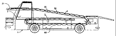
The apparatus of Fig. 1 comprises a vehicle designated the general reference
numeral
1 and provided with a cab 2 and a platform 3. The cab 2 is of a width
corresponding
to approximately half the width of the platform 3. Next to the cab 2, the
vehicle 1
is provided with a ramp 4 tiltably arranged in a manner not described in
greater
detail. This ranlp 4 can be positioned witll a suitable inclination relative
to the plat-
form 3 of the vehicle 1 by means of an actuator 5. The ramp 4 extends
substantially
across the entire length of the vehicle 1, the front end 6 of said ramp being
positioned
in the area around the front side of the cab 2.
The ramp 4 carries a first conveyor part designated the general reference
numeral 7,
and a second conveyor part 7 designated the general reference numeral 8. The
first
conveyor part 7 comprises an endless conveyor belt 9 shown in detail in Figs.
1 to
4 where parts of the four sides of the ramp have been removed for the sake of
clarity.
At the rear end of the ramp 4, this endless conveyor belt 9 runs from a lower
path
10 to an upper path 11 or vice versa tlirough a rear turning member 12 whicll
is
provided with a plurality of rollers 13, 14 and 15. At its front end, the
upper path 11
ends at a redirecting member designated the general reference numeral 16, cf.
also
Figs. 6 and 7. The redirecting member 16 comprises two interconnected rollers
17
and 18 redirecting the conveyor belt 9 to an intermediate path 19 continuing
forwards
towards the front end 6 of the ramp parallel to the upper path 11, but on a
level
therebelow. This intermediate path 19 ends at a front turning member
designated the
general reference numeral 20 and comprising a single roller 21. The conveyor
belt
9 returns to the lower path 10 through the latter single roller 21, said lower
path 10
CA 02396198 2002-07-04
WO 01/51356 PCT/DK01/00012
extending parallel to the upper path 11 and the intermediate path 19.
As shown in particular in Figs. 6 and 7, the redirecting member 16 is by means
of
a U-shaped bracket 22 connected to the rear end of the second conveyor part 8
when
seen in the longitudinal direction of the vehicle 1. As the bracket 22
simultaneously
5 engages suitable guides not shown in greater detail along the sides 23 and
24 of the
ramp 4, cf. Fig. 6, the reciprocating movement of the second conveyor part 8
rela-
tive to the longitudinal direction of the vehicle 1 implies that the
redirecting member
16 follows said movement in such a manner that the upper conveyor patll 11 of
the
first conveyor part 7 is of an increasing or decreasing length in response to
the posi-
10 tion of the rear end of the second conveyor part 8. Within the intermediate
path 19,
the conveyor belt 9 is supported by a supporting plate 25, cf. Fig. 7, through
suitable
means (not shown) for reducing the friction.
Within the upper path 11, the conveyor belt 9 is supported by a supporting
means 26
comprising a high number of interconnected lamellas 27, said lamellas being
hinged-
ly interconnected along the longitudinal side farthest away from the conveyor
belt 9.
At one end, this supporting means 26 is connected to the redirecting member 16
in
such a manner that it follows the movement of said redirecting member 16. In
addi-
tion, the supporting means is adapted to move from a position immediately
adjacent
the lower path 10 to a position below the upper path 11 through the rear end
adjacent
the turning member 12 of said supporting plate 25 in such a manner that the
number
of lamellas in the supporting state below the upper path 11 corresponds
substantially
to the entire length of the upper path 11. If necessary, the movement from one
side
to the opposite side of the supporting plate can be facilitated by means of
guides not
shown in greater detail. In addition, the end of the supporting means 26
farthest away
from the redirecting member 16 can also be connected to said redirecting
member
through conventionally known means in such a manner that the end in question
is
subjected to a tractive force when the redirecting member 16 is moved
downwards
towards the rearmost turning member 12.
CA 02396198 2002-07-04
WO 01/51356 PCT/DK01/00012
11
The second conveyor part 8 comprises a plurality of conveyor units 30, whicll
all are
substantially identical apart from the front conveyor unit 31. All the
conveyor units
30 comprise a continuous belt 32, cf. Fig. 15, driven around suitable rollers
33, 34
and 35. These rollers are journalled in a frame 36 arranged on a support
member 37.
The support member 37 is arranged on rollers 44. The conveyor units 30, 31 are
interconnected by means of flexible coupling means which allow said conveyor
units
to be mutually turned both in horizontal and in vertical direction aiid be
mutually
displaced a short distance in the same directions. The coupling means are
surrounded
by bellow-shaped tubes of rectangular cross sections and with circumferential
waves.
The frames 36 and the support members 37 are made of a suitable plastic
material.
The coupling means are furthermore adapted in a manner not described in
greater
detail to releasably couple the conveyor units 30, 31 together in such a
manner that
said conveyor units are easily replaceable. In addition, the bellow-shaped
tube sur-
rounding the coupling means provides an easy access to passage of a main
distribut-
ing system with associated coupling equipment with the result that the
individual
conveyor units 30, 31 can be supplied with the desired energy, such as
electric
current in an easy manner. As mentioned above, the rearmost conveyor unit 30
is
connected to the redirecting member 16 of the first conveyor part. The
conveyor
units are further provided with such a height that the conveying plane
thereof, i.e.
the upper side of the conveyor belts 32, flushes with the upper path 11 of the
endless
conveyor belt 9, cf. Fig. 7.
The front conveyor unit 31 comprises a rearwardly journalled conveyor flap 39,
cf.
in particular Figs. 13 and 14. In Fig. 13, the conveyor flap 39 is shown in
two
possible positions and in Fig. 14 three possible positions are shown. This
conveyor
flap 39 comprises an endless conveyor belt 40 received in a manner not
described in
greater detail in a frame 41. At the back, the frame 41 is pivotally
journalled in a
manner not described in greater detail in a support member 42 also arranged on
wheels 44, cf. Fig. 1. Jacks 43 are arranged between the frame 41 and the
support
CA 02396198 2002-07-04
WO 01/51356 PCT/DK01/00012
12
member 42, said jacks allowing an adjustment of the conveyor flap 39 in a
position
with a desired inclination.
At the front, the conveyor flap 39 is provided with a pivotally journalled
conveyor
front member 45. When seen from the side, this conveyor front member 45 is of
a
triangular cross section and also associated with an endless conveyor belt 46.
This
conveyor front member 45 can be set with a desired inclination relative to the
con-
veyor flap 39 by means of members not shown in greater detail. The upper side
of
the conveyor belt 46 of the conveyor front member 45 is mainly positioned in a
horizontal plane when the conveyor flap 39 is arranged with a predetermined
inclina-
tion relative to the conveying direction of the remaining conveyor units.
The conveyor front member 45 comprises furthermore wheels 44 implying that
said
conveyor front member 45 can facilitate the support of the relatively far
projecting
conveyor flap 39 together with the support member 42.
Handles 47 and 48 are accommodated on the side of the frame 41 of the conveyor
flap 39. These handles 47 and 48 allow an operator to manoeuvre the second con-
veyor part 8. These handles 47 and 48 are in addition adapted to be used as
control
means such a manner that by a suitable turning of said handles the operator
can
activate or actuate the various driving means not shown of the first and the
second
conveyor parts 7, 8.
An extendable bridge member 50 is mounted in connection with the front end of
the
ramp, cf. Figs. 8 to 12 and 20. This bridge member 50 is tiltable, cf. Fig.
20, and
adapted to be arranged in a substantially horizontal position by means of an
actuator
28 so as to be moved through an opening 51 into a cargo compartment 52 of an
aircraft 53. In Figs. 8 to 12, the door usually closing the opening to a cargo
compart-
ment 52 has been removed. Then the bridge member forms a bridge between the
ramp 4 and the floor 54 of the cargo compartment 52 directly inside the
opening 51.
CA 02396198 2002-07-04
WO 01/51356 PCT/DK01/00012
13
As illustrated in Fig. 8, the bridge member 50 is positioned directly below
the front
conveyor unit 31 when said conveyor unit is in the retracted state on the
ramp. As
illustrated in Fig. 9, the bridge member is moved forwards and through the
opening
51 together with the front conveyor unit 31. This inward movement is carried
out at
the same time as the inclination of the ramp 4 is adjusted so as to mate the
floor 54
of the cargo compartment 52. When the bridge member has been positioned so as
to
rest on the floor 54 inside the cargo compartment 52, the front conveyor unit
is lifted
outwards to one side or the opposite side of said bridge member 50 in such a
manner
that from this position it can be pulled backwards or pushed forwards inside
said
cargo compartment together with the subsequent conveyor units 30. Such a
control
or guiding of the front conveyor unit 31 and the succeeding conveyor units 30
is
enhanced by a raised platform 55 with suitably shaped guiding sides 56 and 57,
said
conveyor units 30 and 31 sliding against said guiding sides during their
movement.
Suitable means not shown couple and uncouple the bridge member to and from the
front conveyor unit 31 in such a manner that together witll said conveyor unit
31 the
bridge member can be moved into and out of the opening 51 of the cargo compart-
ment 52.
During the use of the apparatus according to the invention, the second
conveyor part
is pushed and moved into the cargo compartment in question, cf. Figs. 10 and
11,
where an operator can use said second conveyor part for the loading and
unloading,
respectively, cf. Figs. 16 and 17. As illustrated in Fig. 16, the operator can
let the
luggage 59 be pulled upwards over his legs by means of the conveyor flap 39
and
subsequently by means of the conveyor front member 45 directly on top of a
stack
60 of cargo items. During the unloading, the cargo items are pulled out of the
stack
60 and placed on the front conveyor unit 31 and subsequently moved further out
of
the cargo compartment. During the use of the apparatus, the operator can, of
course,
position and use the conveyor flap 39 as he wishes. All the movements and
stops as
well as the adjustment of the length of the second conveyor part 8 inside the
cargo
compartment in question can by means of the handles 47 be controlled by the
opera-
CA 02396198 2002-07-04
WO 01/51356 PCT/DK01/00012
14
tor according to the prevailing circumstances inside said cargo compartment.
Figs. 18 and 19 illustrate a second embodiment of the apparatus according to
the
invention. Here the conveyor paths of both the first and the second conveyor
part 7
and 8 are formed by a coherent row of conveyor units 30 and 31. The rear end
of
this row of conveyor units is received in a compartment 65 below the platform
3 of
the vehicle 1, and from this position it is moved through the rear end of the
vehicle
upwards onto the ramp as the front end of the row is moved into the cargo
compart-
ment 52 of the aircraft 53. This embodiment is particularly suited for use in
connec-
tion with particularly long cargo compartments 52 requiring a relatively high
number
of conveyor units.
The individual members, and especially the conveyor units of the second
conveyor
part 8 are made maiiAy of plastic materials in response to the desired
strength. Fur-
thermore, additional conveyors 61 and 62 can be mounted at the rear end of the
apparatus so as to facilitate the transition between the equipment for the
advancing
and removal of luggage and the rear end of the first conveyor part 7. All
driving
means are connected to power sources in the vehicle 1 in a manner not
described in
greater detail.
Fig. 21 illustrates a second embodiment of a conveyor unit with a continuous
belt 71
supported by rollers 72 and 73, where the first roller 72 is a driving roller
supplied
with electric energy as indicated through a conduit 116. The rollers 72 and 73
are
journalled in a frame 75 by means of brackets 74 and 75. The frame 75 is at
both
sides provided with a pair of wheels 76 which are protected by means of
screens 77
and 78, respectively, in such a manner that they are uncovered both at the top
and
at the bottom whereby the conveyor units can roll on suitable guides both in a
posi-
tion in which the conveyor belt 71 faces upwards and in a position in which
said
conveyor belt faces downwards, cf. Fig. 24. Screens 79 and 80 are mounted on
the
frame 75 along the sides of the conveyor belt 71.
CA 02396198 2002-07-04
WO 01/51356 PCT/DK01/00012
The conveyor units are joined by means of coupling members 81 and 82
preferably
made of die-cast aluminium. These coupling members 81 and 82 are pivotally
jour-
nalled about axes 83 and 84 in two abutting conveyor units and mutually
pivotally
journalled about an axis 85, a rubber unit 86 being placed between said
coupling
5 members. This rubber unit 86 ensures both a straightening of the conveyor
units
when said conveyor units are not subjected to a mutually turning load, and
provides
a protected passage of electric conduits between the conveyor units through
suitable
channels 87 and 88. The conveyor units carry members 115 co-operating with the
coupling members 81 and 82 in such a manner that they can only turn in one
direc-
10 tion about the axes 83 and 84 away from a common plane through the conveyor
units
parallel to their conveyor paths.
Fig. 22 illustrates a second embodiment of the front conveyor unit. This
conveyor
unit is designated the general reference numeral 90 and coinprises a conveyor
flap
91. At the front, the conveyor flap 91 forms a bend in such a manner that the
front
15 conveyor unit comprises a front member 92 permanently connected to the
remaining
portion of the flap 91. The front conveyor unit 90 comprises an endless
conveyor belt
93 extending over the front member through suitable rollers. In front of the
continu-
ous belt 93, a pair of loosely journalled rollers 94 and 95 are provided. The
conveyor
flap 91 comprises a frame 96, which at the back is pivotally journalled in a
support
member 97. This support member 97 carries jacks 98 and supporting means 99 and
100 which are hingedly mounted on the support member 97 and displaceably mount-
ed on the frame 96. The support member 97 comprises wheels 101 rotatably
arranged
about shafts which extend perpendicular to the plane of the support member 97.
In
addition, one or more wheels 102, cf. Fig. 24, are provided below the front
member
92 of the flap 91, said wheels being of the same type as the wheels 101.
Fig. 23 illustrates a telescoping bridge member 105 comprising guide means 106
and
107. These guide means 106 and 107 allow a guiding of the row of conveyor
units
in the desired direction into the cargo compartment of an aircraft. The front
guide
CA 02396198 2002-07-04
WO 01/51356 PCT/DK01/00012
16
means 107 of the two guide means is arranged on a rotatable disc 108 which
allows
a setting of said guide means 107 in the desired direction. The guide means
106 and
107 are adapted to co-operate with suitable guide members not shown on the
bottom
side of the conveyor units.
Fig. 24 illustrates a third embodiment of the invention. Here the conveyor
path of
the first conveyor part 7 is formed by a first endless conveyor belt 110
mounted
above the path of the conveyor units 70 between a compartment 111 and the
bridge
member 105. The first conveyor part 7 comprises furthermore a front conveying
means with a second continuous belt 112, and which in front tapers in such a
manner
that the cargo items being handled pass in a relatively easy manner to and
from the
first endless conveyor belt of the first conveyor part 7. As indicated in Fig.
24, rails
113 are provided in the compartment 111, and the conveyor units 70 can run on
said
rails by means of the wheels 76 while the endless conveyor belts face
downwards.
The moving of the conveyor units 70 to and from the compartment is carried out
by
means of a driving, endless conveyor belt 114 which co-operates with the
bottom
side of the conveyor units 70 in a suitable manner, such as by way of
friction.
The invention has been described with reference to preferred embodiments. Many
modifications can be carried out without thereby deviating from the scope of
the
invention. The first and the second conveyor parts 7 and 8 and the associated
ramp
4 can for instance be mounted on another equipment than the vehicle. In this
connec-
tion the vital factor is that an adjustment can be performed to the
positioning of the
opening into the cargo compartment in question.
The invention has been described to be used in connection with aircrafts, but
it can,
of course, also be used in other situations where similar circumstances apply.
Instead of lamellas 27, the supporting means 26 can also be provided with
rollers,
and the conveyor units 30, 31 can be adapted to slide in suitable guides on
the sides
CA 02396198 2002-07-04
WO 01/51356 PCT/DK01/00012
17
of the ramp 4 instead of resting on their own wheels as long as they are
positioned
on said ramp 4.