Language selection

Search

Patent 2396493 Summary

Third-party information liability

Some of the information on this Web page has been provided by external sources. The Government of Canada is not responsible for the accuracy, reliability or currency of the information supplied by external sources. Users wishing to rely upon this information should consult directly with the source of the information. Content provided by external sources is not subject to official languages, privacy and accessibility requirements.

Claims and Abstract availability

Any discrepancies in the text and image of the Claims and Abstract are due to differing posting times. Text of the Claims and Abstract are posted:

  • At the time the application is open to public inspection;
  • At the time of issue of the patent (grant).
(12) Patent Application: (11) CA 2396493
(54) English Title: MECHANICAL FACE SEAL DESIGNS FOR SMALL SHAFTS
(54) French Title: MODELES DE JOINT TOURNANT A PORTEE PLANE POUR ARBRES DE PETITE TAILLE
Status: Deemed Abandoned and Beyond the Period of Reinstatement - Pending Response to Notice of Disregarded Communication
Bibliographic Data
(51) International Patent Classification (IPC):
  • F16J 15/54 (2006.01)
(72) Inventors :
  • MILLER, TIMOTHY F. (United States of America)
(73) Owners :
  • TI SPECIALTY POLYMER PRODUCTS, INC.
(71) Applicants :
  • TI SPECIALTY POLYMER PRODUCTS, INC. (United States of America)
(74) Agent: MOFFAT & CO.
(74) Associate agent:
(45) Issued:
(22) Filed Date: 2002-08-01
(41) Open to Public Inspection: 2003-02-01
Examination requested: 2002-08-01
Availability of licence: N/A
Dedicated to the Public: N/A
(25) Language of filing: English

Patent Cooperation Treaty (PCT): No

(30) Application Priority Data:
Application No. Country/Territory Date
60/309,365 (United States of America) 2001-08-01

Abstracts

English Abstract


A drive mechanism includes a housing, a shaft, and a face seal system. The
shaft
is mounted within the housing and is capable of being rotatably driven. The
face seal
system is positioned intermediate the housing and the shaft, the face seal
system being
configured for promoting at least one of a substantially constant load versus
deflection
curve and a substantially flat loading curve with respect to wear thereof.


Claims

Note: Claims are shown in the official language in which they were submitted.

WHAT IS CLAIMED IS:
1. A drive mechanism, comprising:
a housing;
a shaft mounted within said housing, said shaft being capable of being
rotatably
driven;
a face seal system positioned intermediate said housing and said shaft, said
face
seal system being configured for promoting at least one of a substantially
constant load
versus deflection curve and a substantially flat loading curve with respect to
wear thereof.
2. The drive mechanism of claim 1, wherein said housing includes a first
housing
surface and a second housing surface, said first housing surface being
substantially
orthogonal to said shaft, said second housing surface being substantially
orthogonal to said
shaft, said first housing surface, said second housing surface and said shaft
bounding a
housing cavity, said face seal system being located within said housing
cavity.
3. The drive mechanism of claim 1, wherein said face seal system includes a
seal
washer, a sealing element, and at least one of an energizer element and a coil
spring.
4. The drive mechanism of claim 3, wherein said housing includes a first
housing
surface, said first housing surface being substantially orthogonal to said
shaft, said seal
washer being located proximate said first housing surface, said sealing
element abutting
both said seal washer and said shaft, said at least one of an energizer
element and a coil
spring being positioned opposite said seal washer relative to said seal
element.
5. The drive mechanism of claim 4, wherein said at least one of an energizer
element and a coil spring is configured for biasing said sealing element and
said seal
washer against one another.
6. The drive mechanism of claim 3, wherein said at least one of an energizer
element and a coil spring biases said sealing element and said seal washer
against one
another.
7. The drive mechanism of claim 3, further including a retaining clip, said
retaining
clip retaining said seal washer, said sealing element, and said at least one
of an energizer
element and a coil spring in position relative to one another.
5

8. The drive mechanism of claim 3, wherein said face seal system includes a
first
energizer element and a first coil spring, said first energizer element being
positioned
between said sealing element and said first coil spring.
9. The drive mechanism of claim 8, wherein said first energizer element is
configured for statically sealing said face seal system.
10. The drive mechanism of claim 3, wherein said face seal system includes a
first
energizer element and a second energizer element, said first energizer element
being
positioned against said sealing element, said second energizer element being
positioned
against said seal washer.
11. The drive mechanism of claim 10, wherein said face seal system includes a
first coil
spring, said first energizer element being positioned between said sealing
element and said
first coil spring.
12. The drive mechanism of claim 1, further including a bearing mounted
intermediate
said housing and said shaft.
13. A face seal system for facilitating a mounting of a shaft within a
housing, said face
seal system comprising:
a seal washer;
a sealing element, said sealing element having a first element surface and a
second
element surface, said first element surface being substantially flat and
abutting said seal
washer, said second element surface being configured for engaging the shaft;
and
at least one of an energizer element and a coil spring, said at least one of
an
energizer element and a coil spring being positioned opposite said seal washer
relative to
said sealing element, said at least one of an energizer element and a coil
spring biasing
said sealing element and said seal washer against one another.
14. The face seal system of claim 13, wherein said face seal system is
configured for
promoting at least one of a substantially constant load versus deflection
curve and a
substantially flat loading curve with respect to wear thereof.
15. The face seal system of claim 13, further including a retaining clip, said
retaining clip
retaining said seal washer, said sealing element, and said at least one of an
energizer
element and a coil spring in position relative to one another.
6

16. The face seal system of claim 13, wherein said face seal system includes a
first
energizer element and a first coil spring, said first energizer element being
positioned
between said sealing element and said first coil spring.
17. The face seal system of claim 16, wherein said first energizer element is
configured
for statically sealing said face seal system.
18. The face seal system of claim 13, wherein said face seal system includes a
first
energizer element and a second energizer element, said first energizer element
being
positioned against said sealing element, said second energizer element being
positioned
against said seal washer.
19. The face seal system of claim 18, wherein said face seal system includes a
first coil
spring, said first energizer element being positioned between said sealing
element and said
first coil spring.
20. The face seal system of claim 13, wherein said sealing element has a third
element
surface, said face seal system including a first energizer element, said third
element
surface contacting said first energizer element, said third element surface
being angled in
such a manner so as to be configured for biasing said first energizer element
toward the
shaft.
21. The face seal system of claim 13, wherein said face seal system includes a
first
energizer element, said first energizer element being an o-ring.
7

Description

Note: Descriptions are shown in the official language in which they were submitted.


CA 02396493 2002-08-O1
Timothy F. Miller
MECHANICAL FACE SEAL DESIGNS FOR SMALL SHAFTS
BACKGROUND OF THE INVENTION
1. Field of the invention.
The present invention relates generally to mechanical face seals, and more
particularly, to mechanical face seals about small shafts.
2. Description of the related art.
The prior art reveals mechanical seal designs including the use of elastomers
and
springs which created a linear spring or loading curves within the sealing
systems. Such
loading curves caused respective changes in wear-rates such that the internal
loading
could either rise or fall during seal run-in and wear.
What is needed in the art is a mechanical face seal utilizing a flat or
constant load
versus deflection or flat loading curves as a seal element wears. In a typical
application,
face seals may be utilized around shafts in pumps, rotary unions, and other
sealing
environments.
SUMMARY OF THE INVENTION
The present invention comprises a mechanical face seal designed for a small
shaft,
utilizing a combination of a sealing washer or surface with a sealing element
biased by
either a coil spring or a combination coil spring and energizer, such as an o-
ring, to create a
substantially flat or constant load curve versus defection on a seal element.
Such constant
load on the seal faces of the seal system provides for consistent or constant
performance
2 0 with wear of the face elements. Use of an energizer such as an o-ring
provides for static
sealing of the assembly. A metallic or composite retaining clip is used for
connecting the
sealing element, coil spring, and optional o-ring energizer into a unit for
ease of assembly.
The retaining clip is also connected to or attached to the sealing element to
permit
controlled drive to the face seal.
In one form of the invention, a thermoplastic sealing element having, in one
form, a
flat load surface is combined in a sealing assembly with an energizer such as
an o-ring, a
coil spring, and a retaining clip which holds and contains the seal assembly.
An advantage of the present invention is the mechanical face seal and design
thereof, by utilizing a coil spring, during wear and use creates a flat
loading curve or
1

CA 02396493 2002-08-O1
constant load versus deflection curve, thereby providing for constant load and
consistent
performance.
Another advantage is that the o-ring provides static sealing of the assembly.
A further advantage is that the retaining clip permits easy retention to the
shaft.
BRIEF DESCRIPTION OF THE DRAWINGS
The above-mentioned and other features and advantages of this invention, and
the
manner of attaining them, will become more apparent and the invention will be
better
understood by reference to the following description of an embodiment of the
invention
taken in conjunction with the accompanying drawings, wherein:
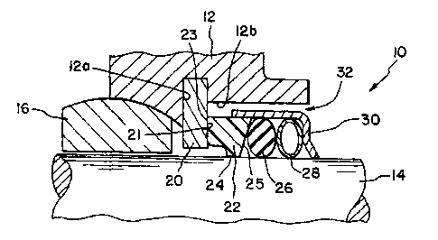
Fig. 1 is a side sectional view of one form of the present invention;
Fig. 2 is a side sectional view of an alternate embodiment of the present
invention;
Fig. 3 is a sectional view of the sealing element of the present invention;
Fig. 4A is a diagrammatic view of an alternate embodiment of the present
invention;
Fig. 4B is a diagrammatic view of an alternate embodiment of the present
invention;
Fig. 5 is a plan view of the retaining clip of the present invention;
Fig. 6 is a side sectional view of the retaining clip of Fig. 5; and
Fig. 7 is a side view of a number of the components of elements of the present
invention.
Corresponding reference characters indicate corresponding parts throughout the
2 o several views. The exemplification set out herein illustrates one
preferred embodiment of
the invention, in one form, and such exemplification is not to be construed as
limiting the
scope of the invention in any manner.
DETAILED DESCRIPTION OF THE INVENTION
Referring to Fig. 1, the present invention in one form thereof, shows a
mechanical
2 5 face seal 10 in a housing 12 located about a shaft 14. As shown in Figs. 1
and 2 a bearing
16 is located immediately between the housing 12 and shaft 14 for appropriate
location of
the shaft to the housing.
The present invention relates to a face seal 10 having a seat washer or face
element 20 attached or connected to a first housing surface 12a of housing 12,
first
3 o housing surface 12a extending substantially orthogonally relative to shaft
14. Housing 12
also includes a second housing face 12b, second housing face 12b extending
substantially
2

CA 02396493 2002-08-O1
parallel to shaft 14. Seal washer or face element 20 may be a separate piece
or a
conjoined or monolithically formed surface of housing 12 and may be formed of
metal.
A sealing element 2~ (Figs. 1-3) is advantageously trapezoidal in shape,
having a
substantially fiat sealing surface 23, a shaft-engaging surface 24 which lies
opposite shaft
14, and a biasing surface 25 which is angled acutely relative to shaft 14. The
flat sealing
surface 23 abuts face element 20 or surface 21 thereon and in combination with
the forces
derived from energizer 26 and coil spring 28, create the performance
characteristics of the
present invention. Biasing surface 25 of sealing element 22 aids in forcing
energizer 26
into contact with shaft 14. Seal element 22 may be made from a conventional
sealing
material, such as a material chosen from the group including PTFE and other
thermoplastics and thermal resins, composites, and alloys.
The energizer 26 adjacent seal element 22 may be made from conventional
elastomeric materials. The energizer 26 is useful in creating static sealing
of face seal 10.
Coil spring 28, adjacent energizer 26, is useful in the invention,
particularly the coil
shown in U.S. Patent 5,542,682 and sold under the trademark name of Slantcoil
(TM). Use
of the coil spring 28 along with the flat sealing surfaces 23 and 24 of
sealing element 22
create a flat or constant loading curve between the face seal 10 and the
sealing washer 20
or its surtace 21.
The face seal system 10 is retained together by a retaining clip 30, as shown
in
2 o Figs. 1, 2, 5, and 6. The retaining clip 30 is useful for connecting
together mechanical seal
10 along with preventing relative rotation of the elements. Retaining clip or
cup 30 may be
formed from stainless steel, another type of metal or alloy, or a composite.
Seal washer 20, sealing element 22, energizer/O-ring 26, coil spring 28, and
retaining clip 30 are substantially positioned within housing cavity 32,
housing cavity 32
being substantially, if not entirely (depending on the embodiment being
viewed), defined by
first housing surtace 12a, second housing surface 12b and shaft 14.
The mechanical face seal 10 is mounted within housing 12 about shaft 14 for
only
axial movement relative thereto, due at least in part to retaining clip or cup
30. The system
10 may further be constrained from moving radially.
3

CA 02396493 2002-08-O1
The mechanical face seal 10 is preferably for use in high speed, medium
pressure
application such as pumps or the like but could be equally well employed in
any drive
mechanism (e.g., motor or pump) using a rotatably driven shaft.
Alternate conceptionaf designs of the system are shown in Figs. 4A and 4B.
Fig. 4A
shows a seat system 10 in which the seal system includes a separately axially
floating seal
washer 20 with an interfit elastomer or second elastomer 36. Fig. 4B shows a
conceptional
view in utilizing two energizers without the use of coil spring 28. The
present invention in
this form still maintains the flat or constant load versus deflection
characteristics.
In some embodiments of use, mechanical face seal 10 may inGude a separate
1 o retainer plate holding the entire assembly in place (not shown).
Figs. 5-7 show different geometries of the seal element 10 parts.
While this invention has been described as having a preferred design, the
present
invention can be further modified within the spirit and scope of this
disclosure. This
application is therefore intended to cover any variations, uses, or
adaptations of the
invention using its general principles. Further, this application is intended
to cover such
departures from the present disclosure as come within known or customary
practice in the
art to which this invention pertains and which fail within the limits of the
appended claims.
4

Representative Drawing
A single figure which represents the drawing illustrating the invention.
Administrative Status

2024-08-01:As part of the Next Generation Patents (NGP) transition, the Canadian Patents Database (CPD) now contains a more detailed Event History, which replicates the Event Log of our new back-office solution.

Please note that "Inactive:" events refers to events no longer in use in our new back-office solution.

For a clearer understanding of the status of the application/patent presented on this page, the site Disclaimer , as well as the definitions for Patent , Event History , Maintenance Fee  and Payment History  should be consulted.

Event History

Description Date
Time Limit for Reversal Expired 2007-08-01
Application Not Reinstated by Deadline 2007-08-01
Inactive: Abandoned - No reply to s.30(2) Rules requisition 2006-08-23
Deemed Abandoned - Failure to Respond to Maintenance Fee Notice 2006-08-01
Inactive: S.30(2) Rules - Examiner requisition 2006-02-23
Letter Sent 2003-06-17
Inactive: Single transfer 2003-04-16
Inactive: Office letter 2003-03-26
Application Published (Open to Public Inspection) 2003-02-01
Inactive: Cover page published 2003-01-31
Inactive: First IPC assigned 2002-10-01
Inactive: Courtesy letter - Evidence 2002-09-17
Letter Sent 2002-09-13
Inactive: Filing certificate - RFE (English) 2002-09-13
Inactive: Applicant deleted 2002-09-13
Filing Requirements Determined Compliant 2002-09-13
Application Received - Regular National 2002-09-13
Request for Examination Requirements Determined Compliant 2002-08-01
All Requirements for Examination Determined Compliant 2002-08-01

Abandonment History

Abandonment Date Reason Reinstatement Date
2006-08-01

Maintenance Fee

The last payment was received on 2005-07-29

Note : If the full payment has not been received on or before the date indicated, a further fee may be required which may be one of the following

  • the reinstatement fee;
  • the late payment fee; or
  • additional fee to reverse deemed expiry.

Please refer to the CIPO Patent Fees web page to see all current fee amounts.

Fee History

Fee Type Anniversary Year Due Date Paid Date
Application fee - standard 2002-08-01
Request for examination - standard 2002-08-01
Registration of a document 2003-04-16
MF (application, 2nd anniv.) - standard 02 2004-08-02 2004-06-02
MF (application, 3rd anniv.) - standard 03 2005-08-01 2005-07-29
Owners on Record

Note: Records showing the ownership history in alphabetical order.

Current Owners on Record
TI SPECIALTY POLYMER PRODUCTS, INC.
Past Owners on Record
TIMOTHY F. MILLER
Past Owners that do not appear in the "Owners on Record" listing will appear in other documentation within the application.
Documents

To view selected files, please enter reCAPTCHA code :


To view images, click a link in the Document Description column. To download the documents, select one or more checkboxes in the first column and then click the "Download Selected in PDF format (Zip Archive)" or the "Download Selected as Single PDF" button.

List of published and non-published patent-specific documents on the CPD .

If you have any difficulty accessing content, you can call the Client Service Centre at 1-866-997-1936 or send them an e-mail at CIPO Client Service Centre.


Document
Description 
Date
(yyyy-mm-dd) 
Number of pages   Size of Image (KB) 
Representative drawing 2002-10-07 1 13
Cover Page 2003-01-06 1 38
Abstract 2002-08-01 1 12
Description 2002-08-01 4 199
Claims 2002-08-01 3 136
Drawings 2002-08-01 3 69
Acknowledgement of Request for Examination 2002-09-13 1 177
Filing Certificate (English) 2002-09-13 1 163
Courtesy - Certificate of registration (related document(s)) 2003-06-17 1 105
Reminder of maintenance fee due 2004-04-05 1 109
Courtesy - Abandonment Letter (Maintenance Fee) 2006-09-26 1 175
Courtesy - Abandonment Letter (R30(2)) 2006-11-01 1 167
Correspondence 2002-09-13 1 24
Fees 2004-06-02 1 36
Fees 2005-07-29 1 36