Note: Descriptions are shown in the official language in which they were submitted.
CA 02396816 2002-07-08
WO 01/51987 PCT/US01/00918
SYSTEM AND METHOD FOR REGISTERING MOTION PICTURE FILM
Background of the Invention
Field of the Invention
The present invention generally relates to motion picture film registration
techniques and, more particularly,
to a system and method for correctly registering frames of motion picture film
during the projection process to provide
enhanced resolution of the projected images.
Description of the Related Art
Film projectors and the motion pictures they project have amazed and delighted
audiences around the world
for over a century. However, the term "motion pictures" is really a
description of an illusion, for the pictures do not
actually move at all. To the contrary, still images, typically 24 per second,
must be projected in as static a manner as
possible. This is not a simple proposition given the fact that in one minute
1,440 images or "pictures" are presented to
the viewer. The illusion of motion is created by the differences between
succeeding still images and is dependent upon
the precise positioning or "registration" of these images with respect to an
aperture in the projector.
One of the problems associated with existing motion picture film projectors
occurs when succeeding images
are positioned in slightly different locations in the projector's aperture.
When this happens, a given point on those
images will appear to be blurred, even if individual images show that point to
be perfectly sharp. Of course, individual
images in motion pictures are not viewed separately, but, rather, over time in
rapid succession.
In the context of motion picture technology, the word "register" (the root for
"registration") is not formally
defined. Perhaps the closest applicable general definition is provided in the
Random House Dictionary Of The English
Lanquape, Second Edition Unabridged (1983): 111b) Print. Correct relation or
exact superimposition, as of colors in
color printing." In the art of motion pictures, however, "registration" has a
slightly different meaning. Motion picture
photographic "registration" means the repeated placement of each image, one
after another, in as precise a manner as
possible throughout the entire chain that comprises the system of cinema
imaging. As described below, there are
several steps in this chain, starting with creation of the image and ending
with its projection.
At the outset, film is moved through the camera intermittently and positioned
by "registration pins" in
precisely the same place, called the "aperture". In this way, a succession of
areas called "frames" are exposed to
light, thus creating "latent images" that become a visible image after
development. Because the "frame" defines the
rectangular space on the film that is occupied by the "image," the terms
"frame" and "image" shall be used
interchangeably and synonymously with each other herein.
During editing and other post-production processes, images created in the
camera are modified when
appropriate. Then they are duplicated for distribution through a process that
involves intermediate steps. These
intermediate steps include contact printing of an inter-positive ("IP"), and
using that IP to make inter-negatives ("IN").
In the next step, the IN is transferred onto release print film via high-speed
contact printing, which is an
unregistered process that operates at up to 17x-play speed, or faster. The
"release prints" made by this process are
distributed to theaters for projection. When the release prints are projected,
the frames are intermittently positioned in
-1-
CA 02396816 2002-07-08
WO 01/51987 PCT/US01/00918
a fixed position relative to the "aperture" of a projector's "gate." Light
from a lamphouse in the projector projects the
images onto a screen for viewing by an audience.
Registration is not a factor in creating high resolution still photographic
images. The photographer and
viewer of a still photograph are concerned only with a single image recorded
and printed from a single piece of film
containing that image. However, registration is a crucial component required
for high resolution imaging in motion
pictures. As noted above, motion pictures are dependent on thousands of images
seen one after another in rapid
succession. Thus, in motion pictures, the collective impression of resolution
or sharpness is highly dependent upon the
repeatable, accurate positioning in the projector of every image that is
photographed and projected.
"Resolution" is another term for sharpness or clarity. In motion pictures,
resolution is a function of several
factors, which include: (1) lens sharpness; (2) film negative granularity; (3)
repeatable, accurate registration of the film
in the camera's aperture; (4) repeatable, accurate registration during
exposure of film IP's, IN's, and release prints; (5)
film print granularity; and (6) repeatable, accurate registration of the
release print in the projector. Of all these factors,
nos. 4 and 6 are the most severely flawed in current motion picture
technology. According, a long-felt need has
existed for a system and method that can address these factors and thereby
provide more precise registration and
enhanced resolution across the entire system of motion picture imaging.
The final measurement of motion picture resolution must be made by analysis of
a projected image at 24
frames per second (standard) or faster, not by inspection of individual frames
as with still photography. Ideally, the
registration precision of the projector should match that of the camera.
Unfortunately, that is not now and never has
been the case. As noted above, motion pictures cameras use highly precise,
mechanically activated'registration pins"
to achieve and maintain final and repeatable film positioning from frame to
frame. On the other hand, theatrical
projectors use registration techniques that are, at best, considerably
inaccurate about both the longitudinal and lateral
axes. This inaccuracy gets progressively worse as various mechanical parts in
the projector's intermittent movement
and gate are subjected to normal wear over time. But the primary cause of this
inaccuracy is the 1 00-year-old design
of the projector movement itself. Projector gates, intermittent sprockets, and
the "Geneva" mechanism that turns
these sprockets in a pause-then-rotate cadence have failed to evolve in any
meaningful manner.
As described more fully below, projector registration in its present state is
primarily achieved by means of
the friction provided by spring tension in the projector gate, acting against
the film, which is advanced by the
rotational movement of the intermittent sprocket. This intermittent sprocket
is typically positioned about 2 to 4
inches or more below the aperture and pulls the film through the gate. When
the intermittent sprocket stops pulling
the film, the spring tension in the gate acts on the film sandwiched within it
and friction causes the film to stop. But
this is a highly passive design that lends itself to imprecision. For example,
gate friction varies due to adjustable spring
tension. Moreover, the film print itself exhibits variable "slickness" due to
waxing, wear and other environmental
factors. Therefore, each succeeding frame simply cannot be registered in the
exact same location as the preceding
frame.
-2-
CA 02396816 2002-07-08
WO 01/51987 PCT/US01/00918
During projection, inaccurate longitudinal registration of the film produces
an up and down film movement
called "jitter," while inaccurate lateral registration produces a side-to-side
film movement called "weave." Both jitter
and weave are greatly magnified by the extreme enlargement of projection. At a
minimum, jitter and weave in any
noticeable amount will result in a softening and blurring of detail and impair
the resolution of the projected images.
The use of larger images on film, as with the various 70mm formats, creates a
sharper image on screen
simply because less enlargement is required to fill the screen. Consequently,
the jitter and weave of the image is less
noticeable with 70mm release prints. However, the higher cost and the lack of
70mm projectors in most theaters
renders the various 70mm formats moot as an option, except in a few "special
venue" theaters. Indeed, if jitter and
weave in the 70mm projectors could be reduced or eliminated, the projected
image would be even sharper.
Current theatrical motion picture projectors inherently create jitter and
weave because they lack any kind of
positive film registration technology. Furthermore, the high=speed printing
process used to manufacture most IP's and
IN's and thousands of release prints distributed to theaters creates yet
another level of jitter and weave in itself. In
order to understand the problems that this causes when the film is finally
projected, it is necessary to understand how
motion picture images are photographed.
In a typical camera movement, film is driven from the camera magazine by a
constant speed sprocket, which
maintains an upper loop of film. A pulldown claw driven by an eccentric cam-
like movement penetrates the film's
perforations and pulls the film into precise registration in the camera's
aperture. The upper loop, much of which is
taken up for this operation, is replenished by the continuous rotation of the
constant speed sprocket. Next, with the
film stopped, the registration pins penetrate adjoining perforations in the
film, while simultaneously the pulldown claw
retracts and begins moving back into position to take hold of the next length
of film to be pulled down. Meanwhile, as
the registration pins penetrate the film's perforations, their tapered teeth
gently move the film into precise position.
The registration pins are restricted to a simple back and forth movement and
are locked in a predictable, repeatable
accurate mechanical design. Also, the registration pins are located
immediately adjacent to and often surrounding the
portion of the film to be exposed. For these reasons, they are very accurate
and allow the camera to expose a
continuous succession of images in precise registration.
In a typical projector movement, however, there is very little similarity to
camera movements. Although a
typical projector has a constant speed sprocket that feeds film to maintain an
upper loop, all similarity to cameras
ends at that point. Unlike a camera, the film's advance into the projector
gate is provided by a powerful pull from an
intermittent sprocket positioned below the projector gate's aperture, through
which light is passed during projection.
The projector gate is a gently curved, spring tensioned "trap" that exerts
friction on the film and thus acts in
opposition to the motive force that pulls film through it. When the
intermittent sprocket stops pulling the film through
the gate, the friction exerted by the gate stops the film. Unfortunately, this
mechanism cannot duplicate the precise
registration provided by cameras for several reasons.
First, the gate's friction, as applied to the movement of the film, is
adjustable and varies from projector to
projector. Higher friction provides heightened opposition to the film's
intermittent movement, but simultaneously
=3-
CA 02396816 2002-07-08
WO 01/51987 PCT/US01/00918
demands that more torque be applied to overcome this static friction for frame-
to-frame advance. This can cause film
stretching or, in extreme cases, breakage. Also, gate friction that is too
high may cause so much film resistance that
the teeth of the intermittent sprocket will deform the perforations in the
film during pulldown, which leads to
deteriorating registration in every subsequent showing of the film. But if
gate friction is reduced too much, the film
may continue moving slightly after the rotation of the intermittent sprocket
stops. In these cases, the film overshoots
the proper location in a way that is prone to be erratic from frame-to-frame.
Second, film prints are often waxed or otherwise provided with a slick surface
in order to slide through the
gate with reduced resistance and/or to help prevent stretching of the film.
This prevents the film from stopping in the
gate in precisely the same place from one frame to the next.
Third, film often shrinks or expands due to age, humidity and other factors.
Thus, the distance from the
image in the aperture to the intermittent sprocket necessarily varies. The
effect of such shrinkage or expansion
increases with greater lengths of film. Therefore, the distance between the
aperture and the intermittent sprocket
includes further margin for error.
Fourth, the mechanism that advances the intermittent sprocket is driven by a
"Geneva" movement, which is
subject to wear. The Geneva movement is well known and comprises a "Maltese"
cross-shaped device, with slots cut
into each cross. A rotating cam-like device turns within it, with a pin that
engages the slots in the cross. This
produces a pause-then-rotate intermittent movement, which is then applied to a
shaft connected to the intermittent
sprocket that pulls the film through the aperture from below the gate.
Although the Geneva movement turns in an oil
bath that is designed to inhibit metal-to-metal contact, like any mechanical
device, there is always some wear. This
wear causes slight imprecision in the application of the motive power to the
connecting shaft, the intermittent
sprocket and the film itself, which is then magnified by the act of
projection.
Fifth, the slightest bend in the shaft connecting the Geneva movement to the
intermittent sprocket will
impart an eccentric movement to the intermittent sprocket, so that instead of
rotating in a circular movement, it will
rotate in a slight oval-shaped pattern. This in turn exacerbates any
imprecision in the Geneva movement, which, in
turn, impairs resolution of the projected image.
Finally, release prints are made on non-registered, high-speed printers that
introduce additional imprecision by
placing the images in different positions with respect to the film edges and
perforations. In other words, this non-
registered printing process microscopically misplaces frames in such a way
that they are no longer located in a precise,
repeatable relationship to the edges and perforations of the film.
Certain special-purpose, pin-registered projectors have been built for a type
of special effects cinematography
called "process shots," but these projectors were not designed for theatrical
projection. Instead, they were designed
to achieve precise registration with the assumption that they would be showing
prints made on some type of relatively
slow, highly accurate printer, rather than release prints duplicated by high-
speed, non-registered contact printers.
Two new projector designs have recently appeared for 70mm special-venue
applications that provide some
equivalent of pin registration. The Mega-Systems projector has two
intermittent sprockets, placed both above and
-4- .
CA 02396816 2002-07-08
WO 01/51987 PCT/US01/00918
below the aperture. A curved, one-sided gate mechanism is brought into
intimate contact with the film by sliding back
toward it. This design is intended to allow for film shrinkage or expansion
while still providing positive registration.
The Linear Loop projector by IWERKS seeks to achieve the equivalent of
positive pin-registration by using blasts of
controlled, compressed air to advance film across a parallel set of linear
sprockets placed on either side of the
projector's aperture. These linear sprockets, which are analogous to railroad
tracks, hold the film's perforations as
succeeding frames are advanced by means of a "standing wave" of film that
rolls across the sprockets, propelled by'
the air blast. Though these two projectors provide registration that
duplicates, somewhat, the positive registration
found in cameras, they do not address the misalignment created by non-
registered high-speed contact printers.
In another area of motion picture technology called "telecine," where motion
picture images are transferred
to videotape, various methods have been developed to achieve a stable image.
While there are differences in the
devices and methods used to achieve image stabilization in these telecine-
based systems (sometimes called "electronic
pin registration"), they all have one thing in common -- they all seek to
stabilize the film image by reference to the film
edges andlor perforations on the film. This is acceptable in telecine, because
telecine uses "low contrast" prints that
are made at 180 feet per minute in "wet gate" contact printers. Thus, the
image position on low contrast prints used
in telecine bears a relatively accurate relationship to the film's edges
andlor perforations. However, the technique of
using the edges andlor perforations on release prints as a reference to
stabilize the film image wrongly assumes that
the images on the film are correctly registered with respect to the edges and
perforations, as they are in the camera or
with prints made on relatively slow, highly accurate printers. As discussed
above, theatrical release prints are made
on non-registered contact printers at speeds often in excess of 1,500 feet per
minute. This high-speed, non-registered
printing process microscopically misplaces frames in such a way that they are
no longer located in a precise,
repeatable relationship to the edges and perforations of the film.
While various types of electronic pin registration andlor image stabilization
methods and technologies work
well when scanning prints made on registered printers, they cannot correct for
improper placement of the image
relative to the edges andlor perforations of the film. As discussed above,
such improper placement is a common
occurrence due to errors engendered in high-speed contact printing of
theatrical release prints. Consequently,
electronic pin registration has limited value for theatrical projection. In
fact, none of these systems were designed
with that purpose in mind. Rather, they all declare to be directed toward the
process of scanning film to video or
digital electronic form.
Accordingly, there has existed a definite need for a system and method that
can achieve precise image
stabilization and enhanced resolution for theatrical motion picture film
projection, that corrects for misplacement of
images on the release print film (compared to the original negative), and
which does not rely on the edges of the film or
its perforations to do so. The present invention satisfies these and other
needs and provides further related
advantages.
-5-
CA 02396816 2002-07-08
WO 01/51987 PCT/US01/00918
Summary of the Invention
The present invention provides a system and method for precisely registering
frames of film with respect to
an aperture in a motion picture film projector. The projector comprises a gate
for receiving and guiding film during
intermittent advancement of the film through the projector. In accordance with
the invention, information is applied to
the film corresponding to the location of the frames on the film. The
information associated with each frame is read
by a sensor prior to projection to determine the location of the frame with
respect to the aperture. If the frame is
misregistered with respect to the aperture once the film stops in the gate, an
actuator moves the film relative to the
aperture to achieve the correct registration. By repeatedly registering the
frames in the exact same location with
respect to the aperture, the resolution of the projected motion picture image
is substantially and advantageously
enhanced.
In conventional projector designs, the gate is connected to the projector in a
fixed manner relative to the
aperture. In accordance with one embodiment of the present invention, however,
the gate is adapted to move relative
to the aperture. Movement of the gate relative to the aperture is provided by
an actuator connected to the gate. In
one form of the invention, the actuator comprises a piezoelectric motor or a
moving coil motor. Both of these types of
motors can be used in conjunction with a flexure stage to provide the required
gate movement. The actuator
preferably is configured to move the gate in increments as small as
approximately 0.000002 inches in about 1
millisecond or less, depending on the frame rate. In addition, the actuator
and the gate are configured such that the
actuator can move the gate at least about 0.006 inches in both the X direction
and the Y direction.
The information necessary to move the gate by the required amount is provided
by the registration
information applied to the film. In one form of the invention, the
registration information comprises a registration
reference mark that is capable of being read by a sensor. The registration
reference mark preferably comprises a
plurality of different shapes that are read by the sensor. In one aspect of
the invention, the plurality of different
shapes comprises at least a circle and a square or rectangle, where the
diameter of the circle is equal to the width of
the square or rectangle. In addition, a triangle may be positioned adjacent to
the circle and the square or rectangle to
provide further registration information.
The registration information is applied to the film in the same location
relative to each frame. In this regard,
the registration information preferably is located on the film in an area
outside the frame, and, most preferably, the
registration information is located in the space between adjacent frames.
Furthermore, if desired, redundant
registration information may be applied to the film for each frame.
The sensor that reads the registration information on the film may take a
variety of forms. In one
embodiment, the sensor comprises a light-based sensor. For example, the sensor
may comprise an LED array on one
side of the gate that transmits light through the registration reference mark
on the film. The transmitted light is
received by a CCD array on the other side of the gate. If desired, one or more
mirrors may be used to reflect the light
transmitted from the LED array onto the CCD array. In addition, redundant
sensors may be used to read redundant
registration information associated with each frame.
=6=
CA 02396816 2007-10-11
A registration processor controls the operation of the sensor and processes
the registration information for
each frame to determine the location of each frame with respect to the
aperture. The location of these frames is
determined by reading the registration information associated with each frame.
The registration processor then uses
the registration information to compare the location of a frame in the gate
relative to the immediately preceding frame.
If a frame is not properly registered with respect to the aperture in the same
place as the immediately preceding frame,
then the registration processor calculates the amount of film misregistration.
Based on the amount of misregistration,
the registration processor generates an appropriate output signal that is
delivered to the actuator. This output signal
commands the actuator to move the gate in such a manner that the frame is
correctly registered relative to the
immediately preceding frame. In this way, each of the frames will be
registered in the same location relative to the
aperture. The output signal may comprise a voltage-based signal, a current-
based signal, or other suitable signal
configured to move the actuator and thus the gate.
In accordance with an aspect of the present invention, there is provided a
method of registering frames of film
with respect to an aperture in a motion picture projector, comprising:
applying registration information to the film
corresponding to a location of the frames on the film; moving the film through
the projector and intermittently stopping
the film frame-by-frame with respect to the aperture; reading the registration
information associated with each frame
prior to projection to determine said location of the frame with respect to
the aperture; determining the amount of
correction that is necessary to achieve proper registration of the frame with
respect to the aperture prior to projection;
and moving the frame into proper registration with respect to the aperture
prior to projection.
According to another aspect of the present invention, there is provided a
system for registering frames of film
in a motion picture film projector having a gate for receiving film during
intermittent advancement of the film through the
projector, comprising: an actuator connected to the gate that is adapted to
move the gate relative to the aperture; a
sensor that reads registration information on the film associated with each
frame to determine a location of the frame
with respect to the aperture prior to projection; and a registration processor
connected to the sensor and the actuator
that is adapted to determine an amount of movement that is necessary to move
the gate and thus the frame into proper
registration with respect to the aperture.
Other features and advantages of the present invention will become apparent
from the following detailed
description, taken in conjunction with the accompanying drawings, which
illustrate, by way of example, the principles
of the invention.
Brief Description of the Drawings
The accompanying drawings illustrate the invention. In such drawings:
FIG. 1 is a diagrammatic representation of the six degrees of freedom for
defining any location in three-
dimensional space. FIG. 2 is a schematic view of film travelling through a
motion picture projector.
FIG. 3 is another schematic view of film travelling through the projector,
showing the maximum amount of roll
of the film in the projector gate.
FIG. 4 is an elevational side view of a conventional motion picture film
projector, showing film travel through
the projector.
-7-
CA 02396816 2007-10-11
FIG. 5 is a schematic view showing the position of the projector gate relative
to an aperture of the projector.
FIG. 6 is a schematic view of a piezo crystal according to one embodiment of
the present invention.
FIG. 7 is a graph depicting the relationship between applied voltage and the
length of the piezo crystal.
FIG. 8 is a schematic illustration of a piezoelectric motor flexure stage,
shown partly in cut-away section,
used to move the projector gate and correct for film frame misregistration, in
accordance with one embodiment of the
invention.
FIG. 9 is a schematic illustration of a moving coil motor used to move the
projector gate, in accordance with
another embodiment of the invention.
FIG. 10 shows a registration reference mark according to one embodiment of the
invention.
FIG. 11 is a section of film showing the location of a registration reference
mark between the frames of the
film.
FIG. 12 shows a matrix CCD array according to one embodiment of the invention.
-7a-
CA 02396816 2002-07-08
WO 01/51987 PCT/US01/00918
FIG. 13 shows a line CCD array according to another embodiment of the
invention.
FIG. 14 is a rear elevational schematic view of a projector gate and
associated projector structure embodying
the novel features of the present invention.
FIG. 15 is a side elevational view of the projector gate and associated
projector, taken along the line A-A of
FIG. 16.
FIG. 16 is a front elevational view of the projector gate and associated
projector structure, similar to FIG.
14.
FIG. 17 shows selected portions of a registration reference mark according to
one embodiment of the
invention.
FIG. 18 shows additional aspects related to the registration reference mark.
FIG. 19 shows another selected portion of the registration reference mark,
including reference lines for
calculation of frame misregistration.
FIG. 20 is a schematic illustration of one alternative for illuminating the
registration reference marks.
FIG. 21 is a schematic illustration of another alternative for illuminating
the registration reference marks.
FIG. 22 is a block diagram showing a registration processor and other related
processor components in
accordance with the present invention.
Detailed Description of the Preferred Embodiments
In accordance with the present invention, film frame misregistration is
detected and corrected on a frame-by-
frame basis to ensure precise registration of each frame with respect to the
projector's aperture. By registering each
frame in the same position with respect to the aperture, the resulting motion
picture, comprised of these individual
projected images, has dramatically enhanced resolution. Proper frame
registration is achieved, and misplacement of
images on release print film is corrected, by making corrective film movements
while the film is intermittently stopped
in the projector gate. As explained below, this precise film registration and
the resulting enhanced film resolution is
provided by making corrective film movements in only two directions,
corresponding to the X direction and the Y
direction.
In this regard, and by way of further background, any type of motion can be
described with reference to six
degrees of freedom. As shown in FIG. 1, these six degrees of freedom comprise
three degrees of linear movement
commonly known as X, Y and Z, and three degrees of angular movement commonly
known as yaw, pitch and roll.
Because film is flat, and because of the way it is captured in the projector
gate, there can be no discernable yaw or
pitch movements of the film. Although there is some thermal shock defocusing
of the film in the Z direction, due to the
heat absorbed by the film from the projector's lamphouse, which causes the
film to deflect slightly, any movement in
the Z direction is considered to be a very minor aspect of misregistration, as
compared to the misregistration of the
film in the X and Y directions.
Further, while it is possible to correct for possible misregistration due to
roll, the magnitude of this movement
is also considered to be relatively small. In this regard, as shown in FIG. 2,
film 10 that travels through the gate is
=8-
CA 02396816 2002-07-08
WO 01/51987 PCT/US01/00918
mechanically guided past the aperture 12 over a long distance compared to the
width of the film. In most projector
designs, the film 10 is guided by mechanical guide means 14, such that the
film has the capacity to deviate in the gate
in the X direction by only about 0.003 inches. As shown in FIG. 3, film 10
that moves by this amount would result in a
maximum roll component of only about 0.049 degrees. This small angular
rotation component is relatively insignificant
and is unlikely to have any noticeable impact on resolution. Thus, the
necessity and cost of correcting it is subject to
question.
In view of the foregoing, and the fact that jitter and weave are the most
significant factors that contribute
to film misregistration, the system and method of the present invention is
designed to detect and correct film
misregistration in the X direction (weave) and the Y direction (jitter). It
should be understood, however, that the
principles of the invention can be applied to detect and correct film
misregistration in other directions as well.
Therefore, the description that follows should not be construed as limiting
the invention to correct misregistration in
the X and Y directions only.
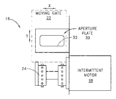
Referring to FIG. 4, a typical 35mm projector 16 has two constant speed
sprockets, comprising a feed
sprocket 18 and a hold-back sprocket 20, located on opposite sides of a film
gate 22. An intermittent sprocket 24 is
also located between the gate 22 and the hold-back sprocket 20, approximately
two to four inches (or more) below the
gate. The intermittent sprocket 24 pulls the film 10 intermittently, frame by
frame, through the film gate 22 in a well-
known manner. Slack in the film 10, in the form of loops of loose film 26 and
28, is provided, respectively, between
the feed sprocket 18 and the film gate 22 and between the intermittent
sprocket 24 and the hold-back sprocket 20 to
prevent film breakage.
The film gate 22 also includes an aperture plate 30 with an aperture 32
designed to be in optical alignment
with a projection light source 34 (such as a lamp house) on one side of the
gate and a lens 36 on the other side of the
gate. A rotating shutter blade (not shown) between the aperture 32 and the
lamp house 34 blocks light from the lamp
house during pull down and registration of the film 10 and permits passage of
light through the aperture upon
registration of a frame 40 with respect to the aperture. The shutter blade or
counter-rotating blades are rotated in a
well known manner by a shutter motor (also not shown).
The gate 22 serves several functions during the projection process. One of
these functions is to
mechanically guide the film 10 through the projector 16. In this sense, the
gate 22 acts as a mechanical alignment
system, whose purpose is to control film movement in the X direction or
"weave." The weave present in today's
projectors primarily occurs as a result of variations in film width and
mechanical deviations in the gate width.
Another purpose of the gate 22 is to apply friction to the film 10, which
stops the film in the gate when the
intermittent sprocket 24 stops pulling the film. In this context, the gate 22
is mechanically similar to a constant drag
system and must have drag components large enough to quickly stop the film 10.
Although the film 10 does not
create a large inertial force, because film is a light material and there is
only a small amount of it moving when the
intermittent sprocket 24 advances the film, a static friction of up to several
pounds is still required to overcome this
-9=
CA 02396816 2002-07-08
WO 01/51987 PCT/US01/00918
inertia effect and stop the film. As between misregistration of the frames 40
in the X direction and the Y direction,
however, misregistration in the Y direction is usually the largest of the two.
Because the gate 22 in conventional projectors is designed to register the
frame 40 with respect to the
aperture 32, the gate is an important aspect of the film registration process.
However, for the reasons previously
explained, it is virtually impossible for conventional projector gate designs
to precisely register the frame 40 in proper
alignment with the aperture 32. Accordingly, to correct for this constant
misregistration from one frame to the next,
the system and method in accordance with one embodiment of the present
invention is designed to physically move the
gate 22, after the film 10 has been stopped in the gate by friction, to
precisely register the frame 40 with respect to
the aperture 32.
FIG. 5 schematically illustrates the position of the gate 22, which, in
accordance with the invention, is
moveable in the X direction and the Y direction relative to the aperture plate
30 of the projector 16 and its
corresponding aperture 32. The intermittent sprocket 24 is located below the
gate 22 and is driven by an intermittent
motor 38. In conventional projectors, as shown in FIG. 4, the gate 22 is
attached to the projector 16 in a fixed
position and therefore does not move. In accordance with the present
invention, however, the gate 22 is configured so
that it can be moved to provide for the necessary corrective movements that
will result in precise registration of the
frame 40 with respect to the aperture 32. In the preferred embodiment, the
gate 22 is configured to move in the X
direction and the Y direction, as necessary, to precisely register the film
10.
The range of gate movement in the X and Y directions preferably is sufficient
to allow enough movement in
each direction to correct for a "worst case" situation of misregistration. A
worst case situation is believed to be a
maximum deviation of about +I- 0.003 inches, although it could be more or less
than this amount. Therefore, to
correct for these deviations, the gate 22 should be able to move at least
about 0.006 inches in both the X direction
and the Y direction. However, it will be understood that a larger range of
gate movement is possible and that the
invention is not limited to the specific ranges of movement set forth herein.
In any event, in order for the range of gate
movement to be able to provide enhanced resolution through precise frame
registration, the corrective movements of
the gate 22 preferably should be at a level and in increments that are at
least on par with the obtainable film grain
resolution available.
According to today's standards, typical film 10 has the capacity to resolve
approximately 4,850 lines per
inch in any axis. In order to correct misregistration and project an image as
a steady picture, gate movement should
ideally be at least ten to one hundred times more precise than the smallest
film grain size. Gate movement at this level
of precision would not only allow the system to accurately position one frame
relative to the next, but it would also
allow for future improvements in film stock technology. Accordingly, in one
aspect of the invention, gate movement
preferably can move the film in increments of 1120 of a micron, or 0.000002
inches.
Movement of the gate 22 to correct misregistration of the film 10 preferably
occurs during the period in
which the film is stopped, after the pull down from the intermittent sprocket
24 and before the shutter opens. During
this period of time, several operations must be performed. As explained in
more detail below, these operations include
-10-
CA 02396816 2002-07-08
WO 01/51987 PCT/US01/00918
determining the position of the film frame 40 relative to the previous frame,
calculating the amount of corrective gate
movement, and then moving the gate 22 accordingly.
Because the frames 40 will be registered at a rate of at least 24 frames per
second (i.e., one frame about
every 41.6 milliseconds), all of these operations, and particularly the
movement of the gate 22, needs to be performed
as quickly as possible. Movement of the gate 22 is accomplished mechanically
and, therefore, is subject to certain
physical limitations. Of course, the shutter will not open until the film 10
has been pulled down and stopped in the
gate 22. If the amount of time to pull down each frame 40 is approximately 8.0
milliseconds, then the operations
necessary to move the gate 22 and register the frame 40 must be performed in
approximately 2.5 milliseconds after
the film 10 has stopped and before the shutter opens. By allowing
approximately 1.5 milliseconds to determine the
location of the frame 40 and to calculate the amount and direction of
corrective gate movement necessary, there is
approximately 1.0 millisecond of time remaining to actually move the gate 22.
If the frame rate is 48 frames per
second, then the amount of time to move the gate 22 will be the same as those
set forth above. Similar calculations
can be made to budget the proper amount of time to move the gate 22 based on
other frame rates that may be used.
In order to move the gate 22 within the time available to do so, the inertia
of the gate ideally should be as
small as possible. Accordingly, the intermittent motor 38 should not be
attached to the gate 22, and the aperture
plate 30 should remain fixed relative to the lens 36 and intermittent motor
38, with the gate 22 moving independently
of both. The actual configuration to permit the gate 22 to move can be
accomplished in several ways, so long as it has
the freedom to move at least about 0.006 inches in the X and Y directions. For
example, flexure stages, bearings,
slides, and other suitable configurations can be used in conjunction with an
appropriately configured gate 22.
In order to move the gate 22 by the distance necessary to accurately correct
frame to frame misregistration,
a movement mechanism is connected to the gate. This gate movement mechanism is
referred to herein as an
"actuator." Given the gate movement parameters discussed above, the actuator
must be able to move the gate 22
rapidly (i.e., in about one millisecond or less). The actuator also must be
able to move the gate 22 in a precise manner
(i.e., preferably in increments of 0.000002 inches). An actuator capable of
meeting these gate movement parameters
may take several different forms. For example, it may comprise a system that
utilizes fluids, air pressure, mechanical
devices or electromechanical devices to provide the required movement. Of
these options, electromechanical devices
are presently preferred, due to the high level of control and the higher speed
response that they provide.
Electromechanical devices come in many different forms, such as rotary or
linear motors, piezoelectric
motors, bi-material actuators, and other devices that change shape or size
based upon an electrical influence. Rotary
motors represent a common system that transfers rotary motion into linear
motion through the use of a screw, cam or
similar device. Linear motors, such as moving coil motors or speaker coil
motors, are also candidates for the actuator
due to their precise movements and quick response time. Bi-material actuators
rely upon the dissimilar nature of two
materials to cause a bowing or shape change that can be converted into precise
linear motion. Of these options,
piezoelectric motors or moving coil motors are presently preferred actuators.
-11-
CA 02396816 2002-07-08
WO 01/51987 PCT/US01/00918
The piezoelectric motor has several attributes that make it a very capable
actuator. Among these attributes
are the piezoelectric motor's high speed capability and its high positional
accuracy. In fact, accurate moves in
increments as small as one nanometer (i.e., one billionth of a meter), or
less, can be achieved, provided proper
mechanics and electronics are employed.
As shown schematically in FIG. 6, a piezoelectric motor 42 employs a piezo
crystal 44 that increases or
decreases in length in proportion to the voltage that is applied across the
crystal. When the voltage across the crystal
44 is increased, the length of the crystal increases, whereas reduced voltage
decreases crystal length (see FIG. 7).
One advantage of using the piezoelectric motor 42 as the actuator is that it
is not necessary to have a feedback loop
or to constantly monitor the actual position and the commanded position of the
gate 22. Feedback systems of this
nature are commonly deployed in motor control applications and would be
required if a moving coil motor (discussed
below) is used as the actuator.
By eliminating the feedback loop, the amount of microprocessor power required
by the piezoelectric motor 42
to both initially move the gate 22 and then keep it in the correct position
during the time the shutter is open is reduced.
Moreover, piezoelectric motors 42 have a highly reliable and predictable move
distance based upon the applied voltage.
As noted above, and as represented in FIGS. 6-7, voltage applied to the piezo
crystal 44 causes it to increase or
decrease by a very precise distance in a linear manner along the axis of the
crystal. Therefore, a simple calculation or
the use of available conversion tables will indicate the exact amount of
voltage that must be applied to increase or
decrease the length of the crystal 44 by any given distance with very high
accuracy. While piezo crystals 44 are
known to have a rebound affect, this effect occurs over an extended period of
time and does not start to occur until at
least several seconds have passed. Therefore, the rebound effect of the
crystals is a very small factor because the
time period between each corrective move is so small.
In one form of the invention, the piezoelectric motor 42 comprises a high-
resolution piezoelectric motor
flexure stage 46. As shown schematically in FIG. 8, the stage 46 comprises two
piezoelectric motors 42 protected by
an outer metal frame 48. The peizoelectric motors 42 have one end connected to
the outer frame 48, which is fixed
against movement, and another end connected to an inner frame 50 that is
moveable with respect to the outer frame
48. As explained later in conjunction with FIGS. 14-16, the moveable inner
frame 50 is connected to the projector
gate 22, and the fixed outer frame 48 is connected to a suitable fixed
structure of the projector 16 that surrounds the
gate.
The stage 46 also includes a plurality of flexures 52, which are frictionless,
stictionless devices that rely
upon the elastic deformation or "flexing" of a solid material. The flexures 52
are connected between the outer frame
48 and the inner frame 50 and advantageously eliminate sliding and rolling.
These flexures 52 essentially act like
springs that bias the moveable inner frame 50 with respect to the fixed outer
frame 48. They are capable of providing
the small increments of movement in response to the linear motion of the
piezoelectric motor 42, in accordance with
the principal of material elastic flexing, to provide mechanical movement
translation. The flexures 52 are also
particularly advantageous because they eliminate the common linear path errors
associated with linear bearings.
.12.
CA 02396816 2002-07-08
WO 01/51987 PCT/US01/00918
Therefore, such flexure-type positioners are superior to traditional
positioners, such as ball bearings, cross roller
bearings, etc., in terms of resolution, straightness and flatness.
The peizoelectric motor flexure stage 46 is preferably equipped with at least
two piezoelectric motors 42.
The flexure stage 46 also may be provided with two high-resolution capacitive
displacement sensors 54, but they are
not required. The piezoelectric motors 42 provide the motion required to move
the gate 22 with sub-nanometer
resolution in the X direction and the Y direction. The capacitive displacement
sensors 54 comprise a probe 56 and a
slightly larger target plate 58. The sensors 54 also have sub-nanometer
resolution and insensitivity to lateral motion.
Digital control electronics connected to the stage 46 by a cable 60 can
evaluate the combined information of the
capacitive displacement sensors 54 and transform that information into two
individual signals proportional to X and Y
linear displacement.
High resolution piezoelectric motor flexure stages 46 of the type described
above, and which have the
capability of moving the gate 22 by the required range of motion, and in the
required increments, are commercially
available and can be obtained from, for example, Physik Instrumente GmbH &
Co., Polytec Platz 1-7, 76337
Waldbronn, Germany. Piezoelectric motor flexure stages 46 available from this
company can provide sub-nanometer
movements and virtually unlimited resolution that is not limited by stick-slip
effects or by threshold voltages. These
stages 46 also have piezoelectric motors 42 that have an extremely fast
expansion and thus provide an extremely fast
responding positional element, with microsecond time constants. Furthermore,
the piezoelectric motors 42 in these
stages 46 have the further advantage that they are solid-state. Thus, they
require no maintenance and are not subject
to wear and tear.
A moving coil motor 62 also may serve as a suitable actuator. The moving coil
motor 62 uses a system very
similar to a speaker. As shown schematically in FIG. 9, the moving coil motor
62 comprises a magnet 64 and a wire
coil 66 surrounding the magnet. Like the piezoelectric transducer flexure
stage 46 discussed above, the moving coil
motor 62 also may be used in conjunction with a flexure stage having a
plurality of flexures and high-resolution
capacitive displacement sensors, including a probe 68 and a slightly larger
target plate 70 to determine position. The
wire coil 66 is connected to the inner frame 72 of the flexure stage that, in
turn, is connected to the projector gate 22.
The magnet 64 is stationary and fixed to the surrounding metal outer frame 74
of the stage. In use, current is passed
through the wire coil 66. By varying the intensity of the current, the wire
coil 66 will be moved relative to the
stationary magnet 64 until an equilibrium is met between the stage flexures
and the force of the magnet pull. In this
way, the inner frame 72 of the stage and thus the gate 22 will be moved with
respect to the outer frame 74 to
properly position the gate 22 and register the frames 40 of the film 10.
The actuator preferably is moved or driven in a linear manner by an actuator
driver. The actuator driver may
comprise any suitable arrangement that allows control over the actuator in
response to either a straight analog signal,
a digitally processed signal, or another suitable signal. When the
piezoelectric motor 42 serves as the actuator, the
actuator driver comprises a voltage controlled system. If the moving coil
motor 62 serves as the actuator, then the
-13-
CA 02396816 2002-07-08
WO 01/51987 PCT/US01/00918
actuator driver is a current controlled system. Other suitable types of
actuator drivers will be apparent and can be
selected based on the type of actuator that is used.
The voltage control system for the piezoelectric motor 42 includes an
electronic system capable of handling
the bandwidth required to move the actuator by its required distance, i.e., at
least 0.006 inches, in one millisecond or
less. For example, a high voltage amplifier-based design taking a control
signal from an analog front end circuit can be
used. The analog front end circuit can be either an analog control circuit or
a digital control circuit that converts to
analog through an analog to digital converter.
The current control system for the moving coil motor 62 is similar to the
voltage control system for the
piezoelectric motor 42, except for the addition of a feedback loop to monitor
the current output of the amplifier stage,
either through an analog circuit or a digital circuit. The feedback loop
monitors the current and adjusts it to follow a
proportional gain value to the control signal coming from the analog front end
circuit. If the current is too low, the
feedback loop increases the voltage until the appropriate current is reached.
Likewise, if the current is too high, the
voltage is decreased until the correct current level is reached.
Having described the electromechanical aspects for physically moving the gate
22, the portion of the system
that governs how far the gate must move, and which direction it must move,
will now be described.
In order to move the gate 22 and position the frames 40 in proper registration
with respect to each other and
the aperture 32, it is necessary to determine the location of the frames once
the film stops moving at the conclusion of
each intermittent pull down by the intermittent sprocket 24: This
determination of frame location from one frame to
the next will reveal the amount of misregistration that needs to be corrected.
In accordance with the present
invention, registration information is applied to the film 10 corresponding to
the location of the frames 40 on the film
10. This information is sensed or "read" in order to determine the frame's
location relative to the frame that preceded
it.
In one form of the invention, the information is embodied in a registration
reference mark 76 adjacent to the
frame 40. In the preferred embodiment, there is at least one registration
reference mark 76 associated with each
frame 40. By detecting the location of the registration reference mark 76 and
comparing its location relative to the
location of the immediately preceding registration reference mark, it is
possible to determine the amount of movement
necessary to correct misregistration on a frame by frame basis. With this
comparative information, the difference
between the locations of two successive registration reference marks 76 can be
calculated and a signal sent to the
actuator commanding it to move the gate 22 so that the two marks lay on top of
each other. Once the registration
reference marks 76 lay on top of each other, then the frames 40 will also.
When the film registration process starts, the first frame 40 with a
registration reference mark 76 acts as a
"benchmark" for the subsequent registration of every frame 40 that follows. In
other words, the location of the first
frame 40 relative to the aperture 32 is determined by sensing the location of
a first registration reference mark
associated with that first frame. The location of the next or second
registration reference mark is also determined,
and the gate 22 is moved so that the second mark lays on top of the first
mark, at the same location as the first mark.
-14-
CA 02396816 2002-07-08
WO 01/51987 PCT/US01/00918
Once the second registration reference mark has been aligned with the first
registration reference mark (at the same
location as the first registration reference mark), then the first and second
frames will also be equally aligned or
"registered." By precisely registering subsequent frames 40 of the film "on
top" of each other in this manner,
substantially all jitter and weave will be eliminated, and the resolution of
the projected image will be substantially
enhanced.
It will be appreciated that, at the beginning of the registration process, the
first "benchmark" frame should
be "centered" as much as possible with respect to the aperture 32. In other
words, the center of the first frame 40
should be aligned as much as possible with the optical axis of the projector
lens 36, which should also be in optical
alignment with the aperture 32. In this way, all subsequent frames 40, which
are registered with respect to the first
frame, will be equally and correctly registered.
The registration references mark 76 can take a variety of different forms. The
main requirement of the
registration reference mark 76 is that it must be capable of being detected by
a process that can determine the
location of the mark and then compare that location to the location of the
previous mark. For example, a circle is
capable of functioning as one aspect of a registration reference mark. The
circle can be located by a sensor and then
compared to the location of the circle associated with the previous frame.
Once the distance between the two circles
and their direction relative to each other have been calculated, the actuator
can move the gate 22 by the corresponding
distance and direction to lay the two circles on top of each other in the
manner described above.
The registration reference mark 76 in accordance with one embodiment of the
invention employs multiple
shapes. As shown in FIG. 10, these shapes may comprise geometric shapes, such
as a square 78, a circle 80 and a
triangle 82. The square 78, by definition, has a constant dimension on all
four sides, i.e., from top to bottom and from
side to side. The circle 80 is placed adjacent to the square 78 and is the
geometric shape used to calculate the amount
of misregistration of each frame 40. The diameter of the circle 80 is the same
as the width of the square 78.
Alternatively, a rectangle may be used instead of the square 78, so long as
the width of the rectangle is the same as
the diameter of the circle 80. The triangle 82 is placed on the other side of
the square 78 from the circle 80. The
base of the triangle 82 is shown aligned with the bottom of the square 78 and
has a length that is the same as the
width of the square, although triangles having other dimensions may be used.
If desired, the registration reference mark 76 may also include additional
information. With reference again
to FIG. 10, optional additional information is set forth to the left of the
three geometric shapes. This other information
may include, for example, binary information 84 indicating the frame size,
film speed, movie title, lab origin, or any
other appropriate information. The binary information may also include
information signaling the start 86 of the
information band at the beginning and a checksum 88 at the end. The type of
message 90 also may be provided.
However, this additional information is not needed or used to determine the
location of the frame 40. Rather, as set
forth above, frame location is determined by the three geometric shapes.
One aspect of the registration reference marks 76 involves the location of
these marks on the film 10 and
the number of marks that are used. Preferably, there is one registration
reference mark 76 associated with each
-15-
CA 02396816 2002-07-08
WO 01/51987 PCT/US01/00918
frame 40. In this way, each and every frame 40 will be precisely registered
and resolution of the projected images will
be maximized. Alternatively, registration reference marks 76 may be applied to
every other frame 40, or in some other
number or convention, to achieve better registration and resolution than
conventional systems, although not as good as
the resolution provided when each frame 40 is registered.
With respect to the location of the registration reference marks 76, each mark
is preferably located on a
portion of the film closely adjacent to each frame 40. In one embodiment shown
in FIG. 11, the registration reference
mark 76 is located in the longitudinal space 92 between each frame 40. This
space 92 is large enough to fit the
registration reference marks 76 in most film formats. The registration
reference marks 76 also could be located on the
outside of the film's perforations 94, or between the perforations. However,
this is not a preferred location because it
is ordinarily occupied by sound track information.
In the alternative, the registration reference mark 76 may be located within
the image itself, but this would
require an image capture system that could scan an image and then interpret
the location of the mark from the entire
frame 40. Accordingly, this approach has certain drawbacks. The registration
reference marks 76 also could be
applied with ink or a magnetic charge that is invisible to the naked eye, but
that could be read by an appropriate
sensor. However, the preferred location of the registration reference marks 76
is immediately outside the frame 40.
By placing the registration reference marks 76 outside the frame 40, they can
be read by the sensor without affecting
the image to be projected. The most preferred location of the registration
reference marks 76 is in the space 92
between each frame 40.
The registration reference marks 76 may be placed on the film 10 in any
suitable manner, preferably during
the manufacture of IN's, IP's or other intermediate printing process, or in
the equivalent digital version of that process
("digital intermediate"), wherein fades, dissolves, titles, effects, color
"timing," density corrections, and other
intermediate processes are handled digitally before scanning back out to film.
For example, the registration reference
marks 76 may be applied to the film by a laser device precisely mounted on a
registered contact "step" printer. The
precise method of mounting the laser device to such a printer will vary with
the different types of printers, and various
techniques exist to modify step printers for placement of such laser devices.
Other suitable devices may be used to
apply the registration reference marks 76, in particular, the outline of the
three geometric shapes. Regardless of the
device that is selected, it must be able to apply the registration reference
marks 76 to the film 10 such that the square
78, circle 80 and triangle 82 are transparent and surrounded or outlined by a
non-transparent portion. Alternatively,
the square 78, circle 80 and triangle 82 may be non-transparent and surrounded
or outlined by a transparent portion.
Laser devices are capable of providing these types of registration reference
marks by use of appropriate masking and
the like, but other suitable devices may be used as desired.
In applying the registration reference marks 76 to the film 10, it is
important to position each registration
reference mark in a location that most closely tracks the exposure of each
frame 40 onto the intermediate film.
Accordingly, each registration reference mark 76 should be applied to the film
10 as close as possible to its
corresponding frame 40 and the operative registration pins of the contact
"step" printer. In this manner, the laser
-16.
CA 02396816 2002-07-08
WO 01/51987 PCT/US01/00918
device, or other suitable device, can precisely apply the registration
reference marks 76 in the same location as each
frame 40 is exposed onto the intermediate film stock.
If the registration reference marks 76 are applied during the "digital
intermediate" process, the marks can be
placed in the correct position by means of the imaging computer and its
associated software. They can then be placed
on the film elements generated thereby using the same film recorder technology
as is used to duplicate the film images
themselves.
Alternatively, if the registration reference marks 76 are applied in the
context of dye-transfer (imbibition,
"IB") printing (e.g. the original TECHNICOLOR 3=strip process), the marks may
be placed prior to making the separation
matrixes, or otherwise as appropriate to insure that they maintain alignment
with the frames 40 themselves
throughout the duplication process. The IB process is fully pin-registered,
unlike standard duplication using multi-layer
Eastmancolor-type film. Therefore, the registration reference marks 76 applied
in this instance will have a less
involved function, in that they need not be used to correct for printing
misalignment, but function simply to insure
correct projector registration by compensating for any possible shrinkage,
expansion or other such variables.
No matter how the registration reference marks 76 are applied, they should be
placed in repeatable precise
position relative to the frame 40. In this regard, prior to the manufacture of
release prints, the image is still precisely
located on the film 10 relative to the perforations. The subsequent process of
high-speed contact printing will produce
errors in image placement relative to the film edges and perforations, for the
reasons described above, such as the
variable high-speed printer transport and inevitable misalignment of the bi-
packed film moving through the printer.
However, because the registration reference marks 76 are aligned to the images
themselves, they will be duplicated in
the same manner, right next to their respective frame 40. Accordingly, one can
still correctly position the image by
simply tracking the registration reference marks 76 and by moving the gate 22
to correctly reposition the film 10
accordingly. Hence, even though the images may no longer be precisely located
relative to the perforations 94 and the
film's edges, they will always be located with precise reference to their
respective registration reference marks 76.
These registration reference marks 76, though they are located between the
projected frames 40 and thus will never
appear on the screen, are duplicated with the images themselves during the
high-speed contact printing process.
An appropriate sensor must be used to detect and "read" the registration
reference marks 76. Preferably,
the sensor is fast-acting and triggerable. The sensor also is one that
preferably operates on the principle of detecting
deviations between light and dark. For example, photocells can not only
determine if something is light or dark, but
also shades of gray between the two. Solar cells can detect varying light
levels and respond at very high speeds.
Magnetic pickup heads can read a portion of the film 10 which has been coded,
and this information may used to
determine the film's location. For the reasons set forth below, LED and CCD
technology is the currently preferred
sensor-based system, However, it will be understood that LED and CCD
technology is not the only suitable sensor
system, and other types of suitable sensors may be used.
CCDs are well-known devices having defined pixels that can be exposed by light
and read digitally. They are
not only very fast, but they also allow direct connection to most digital
systems. Both an X and Y matrix CCD or line
.17.
CA 02396816 2002-07-08
WO 01/51987 PCT/US01/00918
CCD are suitable. As shown in FIGS. 12-13, the difference between them is only
in the number and arrangement of
pixels. The matrix CCD 96, shown in FIG. 12, has a number of pixels 98 in both
the X and Y directions, resulting in an
X-Y matrix. This type of CCD usually takes longer to evaluate due to the
larger number of pixels 98 on the cell. The
line CCD 100, shown in FIG. 13, uses the same technology, but with only a
single row of pixels 98. This single row of
pixels 98 is quicker to read and contains less data to sort and analyze.
In order for the line CCD array to work, the film 10 must be illuminated to
cast the outline of the three
geometric shapes, i.e., the square 78, the circle 80 and the triangle 82, onto
the CCD array 96 or 100. There are
several options available to illuminate the film 10. Of course, the opening of
the shutter will illuminate the mark 76
and thereby expose the CCD. However, if the film 10 is moving while the
shutter is open, it will cause a blurring of the
image on the screen, which is unacceptable.
Therefore, the registration reference mark 76 preferably is illuminated while
the shutter is closed so the
corrective move can be completed before the shutter opens. One way to
illuminate the registration reference marks is
by utilizing an LED array 102. This array can turn on briefly and expose the
CCD array 100 through the film 10 while
the shutter is still closed. The LED array 102 may be either visible-light
based or invisible-light based. The benefit of
the invisible light array is that it prevents any bleed-through light from the
LED array 102 from being projected and
thus visible to the audience. For example, this array could flash 2.5 ms prior
to the opening of the shutter, allowing
enough time for the actuator to move the gate 22 before the shutter opens. The
LED array 102 is the presently
preferred way to illuminate the CCD array 100.
One embodiment of the sensor, using arrays of LEDs and CCDs, is illustrated in
FIGS. 14-16. In this
embodiment, there are two sets of arrays of LEDs 102 and CCDs 100, with one
set above and one set below the
aperture 32 in the aperture plate 30 of the projector '16. This arrangement
provides redundancy and increased
reliability when, for example, there are two registration reference marks 76
associated with each frame 40 and both
sets of arrays 100 and 102 are in use. Alternatively, only one of the sets of
arrays could be used, and if one of the
sets malfunctioned, the other set could be activated to keep the system
operating. However, it is not necessary or
required to use multiple sets of LED and CCD arrays. Therefore, FIGS. 14-16
will be discussed with reference to only
one of the LED/CCD arrays, and it will be understood that the description
applies equally to both sets of arrays.
FIG. 14 is a rear elevational view of the projector gate 22, and FIG. 15 is an
elevational side view of the
projector gate taken along the line A-A of FIG. 16, which is a front
elevational view of the projector gate. Before
discussing the LEDICCD arrays 100 and 102, the piezoelectric motor flexure
stage 46 shown in FIGS. 14-16 will be
discussed briefly. As shown in these drawings, the stage 46 has its moveable
inner frame 50 connected to the
projector gate 22, which has been disconnected from its conventional projector
support structure. The inner frame 50
may be connected to the gate 22 in any suitable manner, such as by bolts,
screws or the like that will provide a secure
connection between the inner frame of the stage and the gate. The outer frame
48 of the stage 46 surrounds the
inner frame 50 and is connected to the adjacent projector structure that is
fixed against movement relative to the gate
-18-
CA 02396816 2002-07-08
WO 01/51987 PCT/US01/00918
22. Thus, movement of the inner frame 50 of the stage 46 will result in
corresponding movement of the gate 22, in
accordance with the principles of the invention.
There is an LED array 102 on the front side of the gate 22, which is to the
right in FIG. 15. This array 102 is
adapted to transmit light through an aperture in the gate 22 and another
aperture 32 in the aperture plate 30 so that
light from the LED array 102 passes through the film 10 when the film is
stopped in the gate 22 during the
intermittent pulldown. Thus, once the film 10 has stopped in the gate 22, the
LED array 102 is quickly activated to
pass light through the registration reference mark 76 associated with the
frame 40 that is about to be projected. As a
result, certain pixels 98 in the CCD array 100 will be illuminated and others
will not, depending on whether the
geometric shapes are transparent or non-transparent. In either case, the light
will pass through the film 10 to the back
side of the gate 22, which is to the left in FIG. 15.
With reference to FIGS. 14 and 15, as the light passes horizontally through
the film 10, the light that passes
through the registration reference mark 76 is received by a first mirror 104.
As shown in FIG. 14, this first mirror 104
reflects the light vertically downwardly toward a second mirror 106. The
reference numeral 108 represents the line of
travel of the light, and the reference numeral 110 represents the band of the
total light that is transmitted. The
second mirror 106 then reflects the transmitted light along a generally
horizontal path outwardly to one side of the
aperture 32, where it is received by the CCD array 100. As a result, the
transmitted light will illuminate certain pixels
98 in the CCD array 100. With this information, the location of the
registration reference mark 76 can be determined.
In the first step of this determination, the number of pixels 98 illuminated
in the CCD array 100 by the first
registration reference mark 76 (associated with the first frame) establishes
the "benchmark" for the registration of all
subsequent frames 40. As noted previously, this "benchmark" frame should be
centered as much as possible with
respect to the optical axis of the projector lens 36. With this information,
the location of the first registration
reference 76 mark with respect to the aperture 32 is determined. This location
will correspond to the center of the
circle 80 and the geometric center of the square 78 for all future
calculations. In other words, this will be the location
of a frame 40 that is properly registered with respect to the aperture 32.
When the LED array 102 is activated again for the next succeeding frame 40,
the light passes through the
registration reference mark 76 associated with that frame and certain pixels
98 of the CCD array 100 are illuminated
again. The number of pixels 98 illuminated by the circle 80 are compared to
the number of pixels 98 illuminated by the
square 78. As shown in FIG. 17, if the number of pixels 98 illuminated by the
square 78 and the circle 80 are equal
(i.e., when W1=W2), then the CCD array 100 necessarily falls directly through
the center of the circle 80 and the
geometric mid-point of the square 78, meaning that the frame 40 is properly
registered in the Y direction with respect
to the aperture 32 and no corrective movement in the Y direction is required.
However, when the number of pixels 98
illuminated by the circle 80 is less than the number illuminated by the square
78 (i.e., when WZ<W,), as shown in FIG.
18, then the frame 40 is misregistered with respect to the aperture 32 and
gate movement. in the Y direction is
required to properly register the frame.
-19-
CA 02396816 2002-07-08
WO 01/51987 PCT/US01/00918
To determine whether the CCD array 100 is located above or below the center of
the circle 80, the pixels 98
illuminated by the triangle 82 are also read. Depending on the number of
pixels 98 that are illuminated by the triangle
82, it can be determined whether the frame 40 needs to be moved in the
positive Y direction or the negative Y direction
to achieve proper registration of the frame. For example, if the number of
pixels 98 illuminated by the triangle 82 is
above a certain value, then it can be determined that the CCD array 100 is
located below the center of the circle 80.
Thus, by comparing all of the CCD array data generated from each geometric
shape, it is possible to determine the
amount of movement and the direction of movement necessary to properly
register each frame 40.
FIG. 19 helps illustrate the calculations associated with the circle 80 that
need to be made to determine the
extent of any misregistration in the Y direction. In FIG. 19, Dc represents
the diameter of the circle 80 and the width
of the square 78. Lc represents the length of a chord of the circle 80 and the
location of the CCD array 100 relative to
the center of the circle. Yd represents the offset of the CCD array 100 in the
Y direction, as measured from the center
of the circle 80. R represents the radius of the circle 80, or'h of D. To
calculate the amount of misregistration in the
Y direction, simple mathematics using the Pythagorean theorem is used
according to the following equation, where Yd
equals the amount of misregistration in the Y direction:
To calculate the amount of misregistration in the X direction, it is necessary
simply to know the location (i.e.,
the pixel) on the CCD array 100 corresponding to the center of the circle 80
of the first registration reference mark 76.
This location will correspond to the center of the circle 80 and the midpoint
on the CCD array 100 for all subsequent
circles. When light from the LED array 102 passes through subsequent circles
80 and illuminates the CCD array 100,
the midpoint of the chord Lc for those circles will be calculated and compared
to the midpoint of the CCD array 100 as
determined by the first circle 80. If there is a difference between the
midpoint of a subsequent circle 80 and the
midpoint of the CCD array 100, then the amount of misregistration in the X
direction can be calculated based on the
difference in distance between these two points.
In view of the above, it will be appreciated that the CCD array also can be
configured to act as the
"benchmark" for the registration of the frames 40, in conjunction with the
registration reference marks 76. For
example, a predefined location on the CCD array can be selected as the
location to which all frames will be moved. By
using the registration reference marks 76 to move all frames 40 a predefined
location on the CCD array, the
undesirable jitter and weave will be eliminated.
One of the advantages of using geometric shapes to comprise the registration
reference mark 76 is that
fluctuations that occur during the film production process, or fluctuations in
the illumination of the marks, will not
affect the results of the gate movement calculations. For example, if film
exposure and reprinting makes the square
78 smaller or larger than its original size, the circle 80 and triangle 82
will change in size by the exact same ratio.
-20-
CA 02396816 2002-07-08
WO 01/51987 PCT/US01/00918
Furthermore, lower or higher power illumination will not affect the ability to
calculate the center of the circle 80
because of the corrective nature of the other two geometric shapes, namely the
square 78 and the triangle 82.
Another possible way to illuminate the CCD array 100, shown in FIG. 20, is to
provide a notch 112 in the
shutter 114 in a way that allows exposure of the CCD array 100 before the
shutter opens. However, this method may
cause a ghosting image across the film while the notch 112 moves across the
film frame 40, which would be
unacceptable.
Alternatively, light from the lamp house 34 may be directed around the film 10
and used to expose the
registration reference mark 76 while the shutter is closed, as shown in FIG.
21. This system would require mirrors
116 or a light pipe, for example, to channel the light to the appropriate
location.
Each of the registration reference marks 76 is read by the sensor as soon as
the film 10 has stopped in the
gate 22. However, sensing the registration reference marks 76 at a different
time is possible and opens some
advanced processing possibilities. For example, if the registration reference
mark 76 is sensed before the frame 40
associated with that mark has stopped in the gate 22, a period of time longer
than 1.5 milliseconds can be used to
analyze the mark. By increasing the time available for analysis, a slower,
less expensive registration processor
(discussed below) may be used. Moreover, if the registration reference mark 76
can be read and analyzed before the
frame 40 is stopped in the gate 22, the gate can be commanded to move toward
the correct position during the pull
down of the frame by the intermittent sprocket 24. This would allow
approximately 10 milliseconds of time to move
the gate 22 instead of 1 millisecond or less if the registration reference
mark 76 is not read until the film 10 fully
stops in the gate 22.
In another aspect of the invention, corrective gate movement could be at least
partially determined by
searching for and determining the existence of a trend of misregistration of
the film 10 from one frame 40 to the next.
Based on the nature of the "trending," basic corrective gate movements could
be predicted and executed. While a
trending system does not cancel all error when the film 10 stops, it should at
least eliminate the errors associated with
the film duplication process. By analyzing how several successive frames 40
have stopped in the gate 22, a film stop
deviation may be trended and corrected by appropriate gate movement. Although
this method could possibly correct
for the major deviations causing misregistration of the frames 40, it is
unlikely to be as accurate as analyzing the
registration reference marks 76 once the film 10 has stopped in the gate 22
and before the shutter 114 has opened.
In accordance with the invention, a registration processor 118 governs the
operation of the system. With
reference to FIG. 22, the registration processor 118 communicates with a host
processor 120 to receive information
related to film format (e.g., a four-perforation per frame format or a
three=perforation per frame format), frame rate,
brightness, and so forth. The host processor 120, in turn, communicates with a
motion processor 122 that controls
operation of the projector 16. The host processor 120 will inform the
registration processor 118 if the film 10
contains registration reference marks 76 and, if so, the type of registration
reference marks being used. The
connection between the host processor 120 and the registration processor 118
also will provide a line of
communication for determining registration status and correct operation.
-21-
CA 02396816 2002-07-08
WO 01/51987 PCT/US01/00918
Upon a command from the host processor 120, the registration processor 118
commences its operation to
precisely register the frames 40. The registration processor 118 will activate
the LED array 102, for example, to
illuminate the registration reference marks 76 which, in turn, project the
outline of the three geometric shapes onto the
sensor, such as a line CCD array 100, in the manner described above. The
registration processor 118 then analyzes
the pixel information gathered from the sensor, sorts through the information
and determines the location of the frame
40 being registered relative to the previous frame. Once this information is
known, the registration processor
calculates the distance, in both the X direction and the Y direction, by which
the frame 40 is misregistered with
respect to the previous frame. This calculation can be in the form of a vector
direction and length, which determines
the corrective direction and distance needed to move the gate 22.
Depending upon the direction and the length of the vector, the amount of
voltage or other signal needed to
move the gate 22 in the X direction andlor the Y direction is calculated. A
command signal containing the necessary
information is then transferred to an actuator processor and driver 124 to
generate an appropriate signal. For
example, if the actuator is the piezoelectric motor 42, then the signal will
be a voltage signal. The actuator processor
and driver 124 amplifies the voltage signal to produce a precise voltage that
is applied, for example, through the cable
60 to the piezoelectric motor flexure stage 46, which then moves the gate 22
in the X andlor Y directions to move the
frame 40 into precise alignment with respect to the previous frame.
The registration processor 118 may take several forms. For example,
commercially available
microprocessors, digital signal processors, microcontrollers, analog circuits
and other suitable processors may be used.
In addition, a combination of these various types of processors can be used to
determine and send the corrective move
signal to the actuator.
In other aspects of the invention, the registration processor 118 may default
to a lower level of frame
registration accuracy, as may be appropriate. For example, if the host
processor 120 informs the registration
processor 118 that the film 10 in the projector 16 does not have registration
reference marks 76, the registration
processor 118 may default to a mode in which the sensor reads the position of
perforations 94 instead of registration
reference marks 76 on the film 10. In this default mode, the sensor would
determine the location of a particular
perforation 94 associated with a frame 40 and place each successive
perforation (associated with each successive
frame) in overlapping relation to the one that preceded it. Even though this
default mode would be less accurate than
systems that read the registration reference marks 76, an increase in film
registration accuracy nevertheless can be
achieved as compared to conventional projectors having no such system.
In another more detailed aspect of the invention, information regarding the
location of the registration
reference marks 76 and the corresponding corrective movements of the gate 22
may be analyzed and stored in the
registration processor 118. By analyzing and storing this information for
enough frames 40, the registration processor
118 may provide an.estimate of the corrective move that will be required
before a frame 40 enters the gate 22. This
provides several advantages.
-22-
CA 02396816 2002-07-08
WO 01/51987 PCT/US01/00918
First, as mentioned previously, this "trending" allows movement of the gate 22
prior to the correct analysis
as the frame 40 is being pulled into the gate. This minimizes the distance the
gate 22 has to move once the actual
move has been calculated. If the majority of the misregistration can be
corrected by gate movement during the actual
pulldown of the frame 40 into the gate 22, then only a minor correction will
be necessary once the film 10 has stopped
moving. Accordingly, if the distance of this final corrective move is small,
it can be performed more quickly than a
longer corrective move.
Second, this trending allows corrective moves to be made with respect to film
frames 40 that do not have
any registration reference marks 76, or where the registration reference marks
have been corrupted in some way and
cannot be read. For example, if the film 10 is damaged or dust or other
contaminants obliterate a registration
reference mark 76, either in whole or in part, it may not be possible to read
the registration reference mark. In these
circumstances, an accurate determination of the corrective action necessary
with respect to that particular frame 40
will not be possible. However, instead of bypassing corrective action with
respect to this frame 40 altogether, the
trend in misregistration of the immediately preceding frames will allow the
registration processor 118 to predict the
proper location of the film frame 40 to correct for as much misregistration as
possible.
As an additional feature, the design of the gate 22, in conjunction with the
motion processor 122 and the
registration processor 118, may include a system to permit high-speed computer
control over the resistance to film
movement in the gate. For example, after the film 10 has stopped in the gate
22, the resistance may be decreased to
provide a low starting friction component when the film is pulled down by the
intermittent sprocket 24. This reduced
gate friction would allow lower peak intermittent sprocket torque and would
reduce the stresses placed on the film 10
by the gate 22 during the intermittent pull down move. Near the end of the
intermittent pull down move, appropriate
friction necessary to stop the film 10 may be reapplied back to the gate 22.
This repeated cycle of decreasing and
increasing gate friction would accomplish the objectives of stopping the film
10 accurately at the end of each pulldown
move, while reducing the work required to move the film at the beginning of
each move.
In view of the foregoing, it will be appreciated that the principles of the
present invention can be applied in
numerous ways to eliminate jitter and weave. For example, instead of using the
registration reference marks 76 to
move the gate 22, these marks can be used to manipulate other components in
the projector as appropriate to
eliminate the jitter and weave. These manipulations can be accomplished by
mechanical, optical and other appropriate
means. Therefore, while a particular form of the invention has been
illustrated and described, it will be apparent that
various modifications can be made without departing from the spirit and scope
of the invention. Accordingly, it is not
intended that the invention be limited, accept as by the appended claims.
-23-