Note: Descriptions are shown in the official language in which they were submitted.
CA 02396900 2002-08-06
Induction Apparatus and Method for Determining Dip Angle in Subterranean Earth
Formations
Field of the Invention
The present invention generally relates to the measurement of electrical
characteristics of
formations surrounding a wellbore. More particularly, the present invention
relates to a method
for determining the dip angle of an earth formation.
Description of the Related Art
The basic principles and techniques for electromagnetic logging for earth
formations are well
known. Induction logging to determine the resistivity (or its inverse,
conductivity) of earth
formations adjacent a borehole, for example, has long been a standard and
important technique
in the search for and recovery of subterranem petroleum deposits. In brief,
the measurements
are made by inducing eddy currents to flow in the formations in response to an
AC transmitter
signal, and then measuring the appropriate characteristics of a receiver
signal generated by the
formation eddy currents. The formation properties identified by these signals
are then recorded
in a log at the surface as a function of the depth of the tool in the
borehole.
It is well known that subterranean formations surrounding an earth borehole
may be anisotropic
with regard to the conduction of electrical currents. The phenomenon of
electrical anisotropy is
generally a consequence of either microscopic or macroscopic geometry, or a
combination
thereof. as follows.
In many sedimentary strata, electrical current flows more easily in a
direction parallel to the
bedding planes, as opposed to a direction perpendicular to the bedding planes.
One reason is
that a great number of mineral crystals possess a flat or elongated shape
(e.g., mica or kaolin).
At the time they were laid down, they naturally took on an orientation
parallel to the plane of
sedimentation. The interstices in the formations are, therefore, generally
parallel to the bedding
CA 02396900 2002-08-06
plane, and the current is able to easily travel along these interstices which
often contain
electrically conductive mineralized water. Such electrical anisotropy,
sometimes call
microscopic anisotropy, is observed mostly in shales.
Subterranean formations are often made up of a series of relatively thin beds
having different
lithological characteristics and, therefore different resistivities. In well
logging systems, the
distances between the electrodes or antennae are great enough that the volume
involved in a
measurement may include several such thin beds. When individual layers are
neither
delineated nor resolved by a logging tool, the tool responds to the formation
as if it were a
macroscopically anisotropic formation. A thinly laminated sand/shale sequence
is a
particularly important example of a macroscopically anisotropic formation.
If a sample is cut from a subterranean formation, the resistivity of the
sample measured with
current flowing parallel to the bedding planes is called the transverse or
horizontal resistivity
The inverse of aH is the horizontal conductivity Wit,. 'The resistivity of the
sample
measured with a current flowing perpendicular to the bedding plane is called
the longitudinal or
vertical resistivity, Ov, and its inverse the vertical conductivity ~v. The
anisotropy coefficient
8 is defined as 8 = 6ti/
In situations where the borehole intersects the formation substantially
perpendicular to the
bedding planes, conventional induction and propagation well logging tools are
sensitive almost
exclusively to the horizontal component of the formation resistivity. When the
borehole
intersects the bedding planes at an angle (a deviated borehole) the tool
readings contain an
influence from the vertical and horizontal resistivities. This is particularly
true when the angle
between the borehole and the normal to the bedding places is large, such as in
directional or
horizontal drilling, where angles near 90° are commonly encountered. In
these situations, the
influence of vertical resistivity can cause discrepancies between measurements
taken in the
-2-
CA 02396900 2005-05-16
~J
same formation in nearby vertical wells, thereby preventing a useful
comparison of these
measurements. In addition, since reservoir evaluation is typically based on
data obtained from
vertical wells, the use of data from wells drilled at high angles may produce
erroneous
estimates of formation reserve, producibility, etc. if proper account is not
taken of the
anisotropy effect and the dip of the bedding layers.
There have been proposed a number of methods to determine vertical and
horizontal resistivity
near a deviated barehole. Hagiwara (U.S. Patent No. 5,966,013) disclosed a
method of
determining certain anisotropic properties of formation using propagation tool
without a priori '',
hnvwledge of the dip angle. In U.S. Patent No. 5,886,526, Wu described a
method of
determining an~isotropic properties of anisotropic earth formations using a
multz-spacing
induction tool with assumed functional dependence between dielectric canstarns
of the
formation and its horizontal and vertical resistivity. Gupta et al. (U.S.
Patent No. 5,999,883)
utilimed a triad induction tool to arrive at an approximate initial guess for
the anisotrapic
formation parameters. Moron and Gianzero (Geophysics, Vol. 44, P. 1264, 1979)
proposed
using a tri-axial tool of zero spacing to determine dip angle. Later floe
spacing was extended to
finite size by Giar~ero et al, (U.S. Patent No. 5,115,198) using a pulsed
induction tool. An
iterative method was used in Goo et al. (U. S. Patent No. 6,393,364). These
attempts to
determine vertical and horiwntal resistivity around a deviated borehole and/or
the dip angle of
the formation have not provided sufficient accuracy_ A new technique is
therefore needed.
SUMMs4RX OF THL 1NVEN'TION
In order to solve at least some of the problems with conventional systerxxs,
according to one
embodiment of the invention, there is provided a method for determining a dip
angle of an
earth formation with respect to a borehole in the formation, wherein the
method includes:
measuring a magnetic coupling between a central set of coils and each of two
outer sets of coils
-3-
CA 02396900 2005-05-16
~~in a tool in the borehole, wherein the sets of coils comprise a combination
of transmitter and
receiver coils, wherein the outer sets of coils are symmetrically spaced from
the central set of
coils; obtaining an approximate dip angle a-from a measured coupling between
the central set
of coils and one of the outer sets of coils; obtaining an approximate dip
angle a+ from a
measured coupling between the central set of coils and an opposing one of the
outer sets of
coils; and obtaining the dip angle a of the formation, wherein the dip angle a
corresponds to
a + a+
a =
2
In a particular case, the central set of coils is a tri-axial receiver array R
with an RZ coil oriented
parallel to a long axis of the tool, an Rx coil oriented perpendicular to the
loz~ axis of the tool,
and as Ry coil oriented perpendicular to both the l~ and R~ coils, and the
outer sets of coils are
tri-axial transmitter arrays T+ and T. each having Tx, Ty, and TZ coils
oriented parallel to the
corresponding coils of the tri-axial rerxiver array.
In this particular case, the obtaining the approximdte dip angle value a_
comprises determining
ttxe approximate dip angle a_, wherein a- corresponds to
-t ~~-xRy ~= 2 ~~-xRy }X z
a ~ tRI1 (T'aj2s~x + ~7-~~r~F '
wherein ~T xRy ~ is the reactive component of a coupling between transmitter T
_x and receiver
R,., (T =Rx ~s is the reactive component of a- roupliztg between transmitter
T_x and receiver Rx,
and ~T-=Ry ~ is the reactive component of the coupling between transmitter T.Z
and receiver Ry;
and the obtaining the approximate dip angle value aw comprises determining the
approximate
dip angle a? , wherein a+ corresponds to
3a _
CA 02396900 2005-05-16
2
a taQ ~ IT+xRy ~x + (T+.r~y ~x
~TazRx /x (T+s~y ~x
wherein ~l'+,~Ry ~ is the reactive component of a couplizxg between
transr~nitter T+,~ and receiver .
Ry, ~~'*$Rx ~x is the reactive component of a coupling between transmitter T+z
and rccoiver Rx,
and {T'+a,Ry ~ is the reactive component of the coupling between transmitter
T+Z arid receiver
Ry.
According to another embodiment of the invention, there is provided a method
for determining
a dip angle of an earth formation with respect to a borehole in the formation,
wherein the
method includes; measuring a magnetic coupling between a central set of coils
and N cuter sets
of coils in a tool in the borehole, wherein the sets of coils comprise a
combination of
transmitter and receiver coils, wherein the N outer sets of coils are
symmetrically spaced from
the central set of coils; for each of the N outer sets of coils, attaining an
approximate dip angle
a_" fromi a measured coupling between the central set of coils and one easy of
the rrth outer
set of coils; obtaining an approximate dip angle a+" from a measured ooapling
between the
central set of coils and an opposing one of the rrth outer sets of coils; and
obtaining tho dip
angle a of the fornnation, wherein the dip autgle a corresponds to
~~' Cx-n +a+n
a= .
N
According to yet another embodiment of the invention, there is provided a
method for
determining the dip angle of an earth formation with respect to a tool in a
borehole in the
farmation, wherein the method compases: measuring a magnetic coupling between
one set of
transmitter coils and one or more pairs of symmetrically-spaced receiver coil
arrays of a tool in
the formation, wherein the sets of receiver coil arrays are symmetrically
spaced about the set of
-3b-
CA 02396900 2005-05-16
ttansnnitter Bails; obtaining a measured value a_ of the formation dip angle,
wherei~ri a_ is
based on measurements from receiver coil arrays R and transmitter array T;
obtaining a
measured value a, of the formation dip angle, wherein a, is based on
measurements from
receiver tail strays R,- and transmitter array T; and obtaining the dip angle
a of the formation,
wherein the dip angle a corresponds to
a + a+
a = ,
2
In this embodiment, the receiver coil arrays R= are multi-axial receiver
arrays with coils
corresponding to the z, x, and y axes, wherein the z axis approximates the
axis of the borehole,
and the receiver coil arrays are located symmetrically along the z-axis such
that the triaxial
ttansrniiter array T is located at z ~ 0 and receiver coil arrays R3 are
respectively located at z =
t L.
In a particular case, the obtaining a measured value a_ of the formation dip
angle further
comprises determining a depth-shift transformed coupling corresponding to:
tall ~ ~T'~ Ylm + ,
~T R x~r ~T~R y~,~
wherein ~T'FR-y~~ is the reactive component of the coupling T,~R_ybetween a
transmitter TA
oriented along an x-axis and a receiver coil R_y oriented along a y-axis, ~T=R-
x ~x is the reactive
component of the coupling ?'=R-s between a transmitter TS oriented along a z-
axis and a
receiver coil R-x oriented along the x-axis, and (~T'FR-y ~X is the reactive
component of the
coupling T=R_y between tratxsmitter Tl oriented along a z-axis and a receiver
coil R_y oriented
along the y-axis; and the obtaining a measured value a+ of the formation dip
angle further
comprises determining a depth-shift ttansforimed coupling corresponding to:
-3c-
CA 02396900 2005-05-16
(~' , 2 1
~_1 C xR+y /x '~ ~xR+y Ix f
C T~~+x F J
wherein (~'rR+y ~ is the reactive component of the coupling T~R~Y between a
transmitter Tt
oriented along an x-axis and a receiver coil Rty oriented along a y-axis, ~T,
Rtx ~ is the reactive
component of the coupling T,R,a hetween a trarxsmitter Tx oriented along a z-
axis and a
receiver coil R,x oriented along the x axis, end tT'=R+y ~X is the reactive
component of the
coupling T=,R+y between transmitter T oriented along a z-axis and a receiver
coil R+y oriented
along the y-axis,
Acxording to still yet another embodiment of the invention, there is provided
a method for
determining a dip angle of an earth formation with respect to a borehple in
the formation,
wherein the method comprises: measuring a niagnctic coupling between a central
set of coils
and Npairs of symmetrically-spaced receiver tail arrays Rio of a tool in the
formation, wherein
the pairs of receiver coil arrays are symmetrically spaced about the set of
transmitter coils; for
each of the N pairs of symmetrically-spaced receiver coil arrays R~",
obtaining an approximate
dip angle a_,~ from a mees,.xu~ed coupling between the transmitter coils and
one receiver coil
array of the rcth pair; obtaining are approximate dip angle a+" from a
measured coupling
between the transmitter coils and an opposing receiver coil array of the rlth
pair; and
obtaining the dip angle a of the formation, wherein the dip angle a
corresponds to:
~N a_n ~' a+n
2
a=
N
In the above embodiments, in a particular case, 6 or more couplings may be
used to generate
dip and strike infozmation. Further, the axes of the transmitters and
receivers may be
independent of the axes of the tool
--3d-
CA 02396900 2005-05-16
BRIEF DESCRIPTIpN OF THE DRAWINGS
A better understanding of the present imrention can be obtained when the
following detailed
description of the preferred embodiment is considered in conjunction with the
following
drawings, in which:
-3e-
CA 02396900 2005-05-16
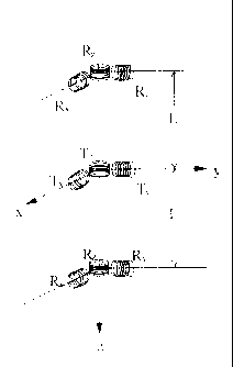
Figure t shows the coil configuration of a triaxial induction tool consisting
of twd triaxial
receivers arrayed symmetrically about a triaxial transmitter;
Figure 2 shows the coil configuration of a triaxial iaduction toot consisting
of two triaxial
transmitters arrayed Symmetrically about a trtiaxial receiver;
Figure 3 illustrates the induction dipmet~ is an earth formation with several
dipping beds,
where the x, y, and z axes correspond to tht coordinate system of the tool,
and the x', y', and z'
axes correspond to the coordinate system of the earth formation;
Figure 4 depicts the correlation between (x,y,a) coordinates in the sonde
system aad (x', y', z')
coordinates in, the earth formation system;
Figuxe 5 shows how the symmetric sonde separates into two independent
subatxays with
transnnitters T and T+ at z = -L and z ~ +L for the upper sonde and lower
sonde, respectively;
and
Figure 6 illustrates the improved accuracy of using the symmetrical triaxial
tool. The upper
graph shows the average of the two values of apparent dip as a function of
logging dapth, and
the lower graph shows the resistivity profile of a foot-bed formation using
tl~e snore accurate
calculation of the formation dip angle.
DETAILEf? DESCRIPTION OF PREFERRED EMBODIMENTS
T~ninologx
It is noted that the terms horizontal and vertical as used herein are defined
to be those directions
parallel to and perpendicular to the bedding plane, respectively.
Tool Confi~ration
Figures I ~ 2 show conceptual sketches for coil arrangements for downhole
induction tools.
Figure Z illustrates a preferred embodimern in which the tool consists of two
Griaxial transmitter
arrays Ixated along the z-axis at equidistant positions above and below the
receiver array R
In each transmitter array, a triad of transmitter coils T'x, Ty and TZ, each
oriented along a
_q _
CA 02396900 2005-05-16
respective axis, is prpvided, as is a similarly oriea~tad triad of receiver
coils 1y Ry, and Itz. It is
assumed that the three oohs in each triad represent actual coils oriented in
mutually
perpendicular directions, with the maxis corresponding to the Iong axis of the
tool. However,
this coil arrangement is not a requirem~t of the invention, as the coil
orientation presumed in
the following deseripdon can be synthesized by performing a suitable
transformation on coils
with different triad orientations. Such tiransformations are described in
depth in LJ.S. Patent No.
6,181,138 entitled "Directional Resistivity Measurements for Azimuthal
Proximity Detectiozt
of Sed Boundaries" and filed February 22, 1999 by T. Hagiwara and H. Song.
In a preferred embodiment, each of the coils in the transmiitter triads T~ is
parallel to the
corresponding coils in the receiver triad R, and eactl is displaced From the
corresponding coil in
the receiver triad by a distance +/ L.
An alternative embodiment exists such that the tool comprises two receivers Rt
located
symmetrically about a transmitter T. Depth shifting techniques may be used to
convert
measurements made by the eimbodimertt shown at Figure 1 into equivalent
measurements that
would have been made by the prefen~d embodimetrt. Applying a depth shift to
the embodiment
disclosed at Fig<tre 1 accounts for the 2L that separates the measured voltage
at receiver arrays
~,+ and R. The use of such depth shi~g techniques is commonly lmown in the
art.
5vstem Model
Generally, a formation model is used to interpret the tool measurements. The
model used
herein is a uniaxial anisotropy model. This model assumes that the formation
is isotropic in the
horizontal direction (parallel to the bedding plane) and anisotropic in the
vertical direction
{perpendicular to the bedding plane). Setting up a formation coordinate system
having the z-
axis perpendicular to the bedding plane and the x- and y-axes parallel to the
bedding plane
allows a conductivity tensor to be expressed as:
-5-
CA 02396900 2002-08-06
a'~, 0 0
= 0 a'h0 (I)
0 0 6,,
The axes of the formation coordinate system typically do not correspond to the
axes of the tool
coordinate system. However, a rotational transform from one to the other can
be defined.
Figure 4 shows a transformation from the tool coordinate system (x, y, z) to
the formation
coordinate system (x", y", z"). The tool coordinate system (x, y, z) is first
rotated about the z-
axis by an angle /~ hereinafter termed the strike angle. The intermediate
coordinate system
(x', y', z' = z) thus formed is then rotated about the y' axis by an angle a ,
hereinafter termed
the dip angle to obtain the formation coordinate system (x", y" = y', z").
Figure 3 illustrates a
uniaxial anistropic formation with a dip a traversed by a sonde with an axis
(x, y, z).
Any vector v" in the formation coordinate system can be expressed in the tool
coordinate
system as:
v = Rv" (2)
where the rotational transform matrix is:
cosa cos/3 cosy sin ~3 - sing
R = - sina cos/3 0 (3)
sina cos/3 sina sin~3 cosa
I S Once the rotational transformation is defined, the focus turns to the
induction tool
measurements. When a voltage is applied to one of the transmitter coils, a
changing magnetic
field is produced. The magnetic field interacts with the formation to induce a
voltage in the
receiver coils. Each of the transmitter coils is excited in turn, and the
voltage produced at each
of the receiver coils is measured. Using either two triaxial transmitters and
one triaxial receiver
or one triaxial transmitter and two triaxial receivers generates measured
voltages that indicate
I 8 magnetic couplings between the transmitters and receivers.
-6-
CA 02396900 2005-05-16
For siutplicity, the apparent dip generated by the measured nrzagnetic
couplings between
transmitter and receiver triads will be addressed as separate induction
dipmeters with the
couplings TR and T+R. Figure 5 shows the separate coupling of triads to obtain
calculations as
Functions of voltage supplied through T. and T+, respec~tirrely. Each coupling
consists of the
receiver array, R, and a transmitter, either T+ or T~ wherein the receiver
array measures the
~roltages produced by each transmitter separately. Onct the mvalues for each
transmitter T+ aad T- array are recorded, the preferred embodiment allows for
the separate
calculations of the ~ dip and strike angles, which are subsequently used to
obtain a more
accurate determination of dip and strike angle for the entire formation.
The most general case according to Moran and Crianzero (Geophysics, VoI. 44,
P. 1266, 1979)
involves the magnetic filed F~ represented by a coupling matrix C. Each triad
coupling T R
or T+R comprises 9 separate magnetic couplings represented by the following
coupling matrix:
H~ C~ C~ C,~ Mu
Hsy ~ t=-'yr C,y C-'y~ M=,, (4)
H~ Ca C'~ C~ M~=
Where H==, Hsy, H=a and M~x, M~r, Ms, are the field components at the
receivers and
magnetic moment components at tile transmitters, respectively. Using these
couplings,
~uations can be derived and manipulated to solve for the strike angle ~B , the
appazent dip
angle a , the horizontal conductivity Q , and the vertical anisotropy A .
These equations and
their derivation are explained in depth in Gao et ah, U.S. Patent No.
6,393,364.
Ass~ning the tool is oriented so that the strike angle is zero, it can be
shown that for the
uniaxial anisotropy model the full coupling matrix C", eotresponding to the
forrnatiozt
coardinate system at the receiver coils (x = 4, z = L) simplifies to:
C,~ 0 C~,
c» = o C~, o (s)
c= o C
-7-
CA 02396900 2002-08-06
wherein the theoretical values of the coupling matrix elements are ~C,~ = C~;
~:
ik,,l_9 _ ,khl.
C..~r = 1 3 k,; LZ cos' a ~ e'k'~'' - ik,,L a ~ a + (3 sin' a -1) (1-
ik,,L)e'k,,~ (6)
4~L sin' a
C.x~ - C,= = 0
_ -smacosa ,k r. _ _ z z
4~L3 a ~~ ~(1 ik,'L) k~, L
2 2 ik~,l..4 _ ik,,~:
c~='' 4~L3 ~,A' e~k~~l, +ik,,L a sin'- a - (1-ik,'L)e,k,,r.
C__ = 4~L3 e'k'~'' ~k,; LZ sinZ a+(1-ik,,L)(3cos' a-1)~ (10)
Likewise, the six independent measurements for all possible couplings between
all transmitter-
receiver pairs are expressed as (T;R~ = TjR;):
TYRO= ~ ~((C.,'_rr+C,_)+(CKr-C__)cos2a+2C',.=sin2a~cos2(3+2C',~,sin'(3l (11)
M
T~, Rv = 2 ~~(C.'.YY + C,_ ) + (C.Y.Y - C__ ) cos 2a + 2C.Y_ sin 2a~in' ~i +
2C'.~, cos' (3 ~ ( 12)
M
T_ R_ = 2 ~(C,.Y + C" ) + (C _. - C,Y ) cos 2a - 2C'Y= sin 2a~ ( 13)
TYR~,= 4 ~(Cr,Y+C'__)+(C'rY-C__)cos2a+2CY_sin2a-2C,.,.~in2~3 (14)
T R,. _ ~ ~(C__ -C.'_YX)sin2a+2C Y= cos2a~cos(3 (15)
M
i5 T_R,, =-~(C_, -C,.,)sin2a+2C,~cos2a~sin(3 (16)
_ 2 _. _
These measurements are made by taking the ratio of the transmit and receive
voltage signals,
e.g., TxRy. = K VRy/VT" where K is a real-valued calibration constant
theoretically equal to
A,. N,. I,. A" N,z ~cvu ~' l 4~L ~ where the magnetic moment, MtT> is equal to
At~rNtTlt~r, wherein
_g_
CA 02396900 2002-08-06
Af~r, Ntr, and It~r correspond to the area, number of turns, and current of
the transmitter coils,
respectively, AR is the area of the receive coil, and NR is the number of
turns of the receive coil.
Explicitly solving equations (13)-(16) results in the following expressions
for the measured
cross-coupling fields (note that the calculations below must be performed for
each of the
transmitters T+ and T_):
MSln?~ 0 2 ik,,l. eik,,~.~! ,k,,i,-1 ik,,l. ('f-COS~ a)
TY R ~; = 3 k,, L a , - ik,, L ~ - a ~ ( 17-a)
8~rL ~.-A sm a
T'R_Y - Mcos(3sin2a.ik~,L~eik,,~..1 -eak,,~. (17-b)
8~tL sin' a
M sin (3 sin 2oc
T R,, _ ~ ~ ikhL ~e~k,,~..a _ etk,,~, ~ (1 ~-c)
8~L- sin- a
T R, = 4~ 3 ~Ze'k"'. (1-ik,,L)-ik,,L~e'k~,i.:a _~ik~,~.~~ (l~-d)
To make practical use of the above equations, the real component is ignored
and the imaginary
(reactive) component is simplified by finding the limit as the transmitter-
receiver spacing
approaches zero, i.e., L -~ 0. Doing this simplifies the reactive components
of the measured
signal equations (18-a,b,c) to:
M sin 2,Q sin a ,
~T+_C Rl. ~Y ~ (1- ~' ) ( 18-a)
8~c~' 8;,
M cos ~3 sin 2a _ _,
~T+_ R.r ~, ~ 8~r~,'8;, (1 ~i, ) ( 18-b)
M sin /3 sin 2cx _ ,
8~~' 8,, (1 ~,' ) ( 18-c)
where $,, = 2/c,~~.a,, is the skin depth associated with horizontal
conductivity. From these
equations, one arrives at the practical equations for the determination of dip
and strike angles:
_~ ~+= R,: ~,
= tari ( )
Tt-Rr r 19
-9-
CA 02396900 2005-05-16
zR i
a= a t~ _, ~*r y ~F * ~*r y ~_ (2d)
*=R; ~ *=RY x
As noted in Goo et al. U.S. l'atetyt No. 6,393,364, the strike angle ~i
obtained is exact while the
dip angle a is only an approximation because ~uations (1$a-c) are valid only
in the zcro:
spacing limit. The subscript + denotes that values are obtained for each of
the tran.~nitters
located at +L and L.
Whereas methods in the past have used an itez~ative process to determine
closer approximations
of the dip angle a , a sinnpler methpd exists in the present invention. A new
method is now
proposed which compensates for the presence of surface charges located at the
boundaries of
formation layers that a#~'eCt measured voltages in the receivers of dipmeters.
By using the
1D stated embodiment, tvao values for the dip angle-one measured from a
transmitter located
above the receiver at a distance L and one measured from a transmitter located
below the
receiver at a distaraee +L--can be averagod to determine a more accurate
estimation of the dip
angle:
a = a_ +a+ . (21)
0 2
By using equidistant transmitters, the surface charge is effectively cancelled
with respect m the
measured voltages in the receiver. Figure 6 illustrates the resulting
calculation of dip angle at
various logging depths.
Another embodiment comprises mutually symmetrical receiver pairs about a
triaxial
transmitter. A depth-shift transformation, commonly known to those of ordinary
skill in the
art, may be used to transform the values obtained at one the receivers to
conform to the location
of the other. Ire calculations and method for determining dip angle is
identical after the
measured values have been transformed to compensate for the distance 2L at
which the values
were measured.
_ 10,
CA 02396900 2002-08-06
Additional embodiments of the claimed subject matter exist wherein the tool
comprises a
plurality of mutually symmetrical triaxial transmitters or receivers located
symmetrically about
a receiver or transmitter, respectively, such that the apparent dip angle of
the formation
corresponds to the average of the apparent dip angles calculated from each
mutually
symmetrical array:
- ~~ Ca-.. + a+,~
a - 2 . (22)
n
It is further emphasized that through the more accurate calculation of
formation dip angle, other
formation parameters, such as formation anisotropy, vertical and horizontal
conductivity and
resistivity, and strike angle will be capable of more accurate determination
as well, as such
parameters are calculated as functions of the formation dip angle.
-11-