Language selection

Search

Patent 2396929 Summary

Third-party information liability

Some of the information on this Web page has been provided by external sources. The Government of Canada is not responsible for the accuracy, reliability or currency of the information supplied by external sources. Users wishing to rely upon this information should consult directly with the source of the information. Content provided by external sources is not subject to official languages, privacy and accessibility requirements.

Claims and Abstract availability

Any discrepancies in the text and image of the Claims and Abstract are due to differing posting times. Text of the Claims and Abstract are posted:

  • At the time the application is open to public inspection;
  • At the time of issue of the patent (grant).
(12) Patent Application: (11) CA 2396929
(54) English Title: LUMINOUS ELEMENT FOR AN INCANDESCENT LAMP
(54) French Title: ELEMENT LUMINEUX D'UNE LAMPE
Status: Deemed Abandoned and Beyond the Period of Reinstatement - Pending Response to Notice of Disregarded Communication
Bibliographic Data
(51) International Patent Classification (IPC):
  • H01K 1/14 (2006.01)
  • H01K 3/02 (2006.01)
(72) Inventors :
  • FRANCK, FELIX (Germany)
(73) Owners :
  • PATENT-TREUHAND-GESELLSCHAFT FUER ELEKTRISCHE GLUEHLAMPEN MBH
(71) Applicants :
  • PATENT-TREUHAND-GESELLSCHAFT FUER ELEKTRISCHE GLUEHLAMPEN MBH (Germany)
(74) Agent: SMART & BIGGAR LP
(74) Associate agent:
(45) Issued:
(86) PCT Filing Date: 2000-11-30
(87) Open to Public Inspection: 2001-07-19
Examination requested: 2005-07-28
Availability of licence: N/A
Dedicated to the Public: N/A
(25) Language of filing: English

Patent Cooperation Treaty (PCT): Yes
(86) PCT Filing Number: PCT/DE2000/004272
(87) International Publication Number: WO 2001052305
(85) National Entry: 2002-07-10

(30) Application Priority Data:
Application No. Country/Territory Date
100 01 007.5 (Germany) 2000-01-12

Abstracts

English Abstract


The invention relates to a luminous element for a lamp. Said luminous element
(10) is double helix-shaped, with two connection parts (18, 20) situated at
one end of said double helix. The diameter (D1, D2) of the double helix
increases consistently in the direction of the two connection parts (18, 20)
of the luminous element (10). The invention also relates to a lamp with a
luminous element of this type, to a method for producing a luminous element of
this type and to a device for carrying out the production method.


French Abstract

L'invention concerne l'élément lumineux d'une lampe. Cet élément lumineux (10) a la forme d'une double hélice dont une extrémité est pourvue de deux raccordements (18, 20) et dont le diamètre (D1, D2) augmente progressivement en direction des deux raccordements (18, 20). L'invention concerne également une lampe dotée d'un tel élément lumineux, un procédé de production d'un tel élément lumineux et un dispositif permettant de mettre en oeuvre ce procédé de production.

Claims

Note: Claims are shown in the official language in which they were submitted.

-7-
What is claimed is:
1. A luminous element for an incandescent lamp, the
luminous element (10) having the shape of a double helix with
two terminals (18, 20) arranged at one end of the double
helix, characterized in that the diameter (D1, D2) of the
double helix increases continuously in the direction of the
two terminals (18, 20) of the luminous element (10).
2. The luminous element as claimed in claim 1,
characterized in that the lead (S1, S2) of the turns of the
double helix increases continuously in the direction of the
terminals (18, 20) of the luminous element (10).
3. The luminous element as claimed in claim 1 or 2,
characterized in that the continuous increase comprises, in
particular, a linear, quadratic, cubic or exponential
increase.
4. An incandescent lamp having a luminous element as
claimed in one of claims 1 to 3.
5. A method for producing a luminous element,
characterized by the following steps:
a. fixing a wire (24) forming the luminous element (10)
on the first end (25) of a rotationally symmetrical
winding spindle (26) whose diameter increases
continuously from its first end (25) up to a winding
end section (32);

-8-
b. winding the wire (24) on the winding spindle (26)
between a first end (25) and the winding end section
(32), the turns being arranged offset on the winding
spindle (26); and
c. drawing the luminous element (10) off from the winding
spindle (26) .
6. The method as claimed in claim 5, characterized in
that in step a) the wire (24) is inserted into a notch (30) on
the first end (25) of the winding spindle (26).
7. The method as claimed in claim 5 or 6, characterized
in that after step b) and before step c) each free wire end is
bent over on a bent-over section (28a, 28b) of the winding
spindle (26) such that after being bent over, the wire ends
are orientated substantially in the direction of the
longitudinal axis of the winding spindle (26).
8. The method as claimed in one of claims 5 to 7,
characterized in that step b) is performed in such a way that
the lead (S1, S2) of the windings on the winding spindle (26)
increases continuously from the narrow end (25) of the winding
spindle (26) to the winding end section (32).
9. The method as claimed in one of claims 5 to 8,
characterized in that the continuous increase comprises, in
particular, a linear, quadratic, cubic or exponential
increase.

-9-
10. A device for carrying out the method as claimed in
one of claims 5 to 9.

Description

Note: Descriptions are shown in the official language in which they were submitted.


CA 02396929 2002-07-10
LUMINOUS ELEMENT FOR AN INCANDESCENT LAMP
Technical Field
The present invention relates to a luminous element for an
incandescent lamp, in particular a luminous element having the
shape of a double helix, with two terminals arranged at one end
of the double helix. It also relates to an incandescent lamp
having such a luminous element, a method for producing such a
luminous element, and a device for carrying out the method of
production.
Prior Art
A luminous element in accordance with the preamble of claim
1 is disclosed in DE 44 20 607, see Figure 3 there and associated
description. Such a luminous element has the disadvantage,
however, that it is very susceptible to the flashovers in the
region of the lowermost pair of turns. Because of tolerances in
the production of the luminous element, during pinching of the
luminous element, that is to say its mounting in a base,
deformations are produced that lead to an exacerbation o~ said
problem.
Summary of the Invention
It is an object of the present invention to provide a
luminous element in accordance with the preamble of claim 1 that
has a reduced susceptibility to flashovers, in particular in the
region of the lowermost pair of turns.
This object is achieved in the case of a luminous element
having the features of the preamble of claim 1 by means of the

CA 02396929 2002-07-10
-2-
features of the characterizing part of claim 1. The mutual
spacing of adjacent turns from one another in space is enlarged
by the measure according to the invention. This results in a
substantially lower sensitivity to position tolerances during
pinching.
The embodiment according to the invention continues to offer
the advantages known from the prior art: for example, the
currents flowing in the respectively adjacent turns are always
in opposite directions. The individual turns therefore repel one
to another in opposite directions because of the filament current.
By comparison with a simple helix, the electric inductance for
the double helix is substantially lower, that is to say the lamp
is more efficient as regards its generation of useful radiation,
and emits less electromagnetic interference. Furthermore, the
design of a luminous element in accordance with a double helix
permits the active filament length to be adjusted continuously,
since the orientation of the transverse connection of the two
halves of the double helix can be selected at will with reference
to the terminals. This results in a far-reaching complete design
2o freedom for the variables of diameter, height, wire thickness and
power.
In the case of a particularly advantageous embodiment, it
is not only the diameter of the double helix that increases
continuously in the direction of the two terminals of the
luminous element, but also the lead of the turns, that is to say
the spacing of adjacent turns from one another. This results in
a further enlargement of a three-dimensional spacing. The second
measure, that is to say the increase in the lead of the turns

CA 02396929 2002-07-10
-3-
alone, does not achieve the above named object, since the double
helix has the lowest mechanical stability at the
end at which the terminals are located. Consequently, if only the
lead of the turns is enlarged, this results in an even lower
mechanical stability. Movements inside the body of the lamp, in
particular owing to the inductive processes during switching on,
therefore lead to an even greater readiness to short circuit . The
sensitivity to position tolerances during pinching is also not
reduced in the case of sole application of the second measure,
l0 since these position tolerances chiefly occur transverse to the
longitudinal axis of the luminous element.
The purpose of the continuous increase is to bring about a
continuous enlargement of the three-dimensional spacing of the
turns since, when only the last two turns have a larger spacing
from one another, the problem is displaced onto the last turn but
one. Consequently, continuous increase is to be understood, in
particular, as a linear, quadratic, cubic or exponential
increase.
The invention also relates to a method for producing a
luminous element according to the invention as claimed in claim
5, and to a device for carrying out the method of production
asclaimed in claim 10.
In a particularly advantageous embodiment of the method
according to the invention, the wire forming the luminous element
is inserted simply into a notch on the narrow end of the winding
spindle before the double helix is formed by winding the wire on
the spindle. In order to observe very close tolerances, it is
particularly advantageous to bend the terminals into shape as

CA 02396929 2002-07-10
-4-
early as in the state in which the double helix is wound stably
onto the winding spindle. For this purpose, each free wire end
is bent over on a bent-over section of the winding spindle such
that after being bent over the wire ends are orientated
substantially in the direction of the longitudinal axis of the
winding spindle. As a result of this there is no need to append
any subsequent processing step that would have the purpose of
bending the terminals into shape. This leads to a minimization
of the risk of undesirably bending the luminous element out of
1o its optimum shape. Winding the wire on the winding spindle can
be achieved by rotating the wire about a fixed winding spindle,
or rotating the winding spindle about its longitudinal axis
between non-rotating wire feeds. In order to achieve a
particularly advantageous embodiment of the luminous element,
this relative movement can be performed in such a way that the
lead of the turns on the winding spindle increases continuously
from the narrow end of the winding spindle to the winding end
section.
Further advantageous embodiments of the invention can be
2o added from the subclaims.
Description of the Drawinas
Exemplary embodiments of the invention are described in more
detail below with reference to the attached drawings, in which,
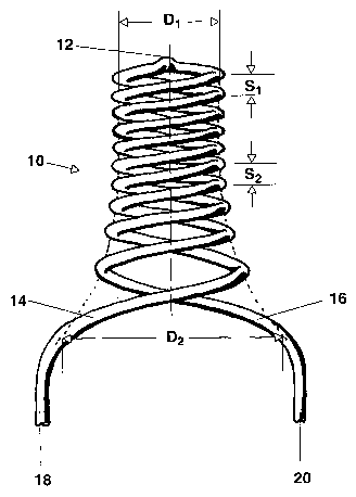
Figure 1 shows a side view of a luminous element according
to the invention
Figure 2 shows a sequence for explaining the method of
production according to the invention; and

CA 02396929 2002-07-10
-5-
Figure 3 shows a detailed view of a winding spindle such as
is used in the method of production according to the invention
and in the device for carrying out the method of production.
Figure 1 shows a luminous element 10 in the shape of a
double helix. In this case, a departing section 14 is connected
via a transverse connection 12 to a returning section 16. The
luminous element 10 has the shape of a double helix. The turns
of the double helix have a diameter D1 at the end of the
transverse connection 12, and a diameter D2 at the end of the
l0 terminals 18, 20. At the end of the double helix where the
transverse connection 12 is situated, the turns have a lead S1,
while at the end where the terminals 18,20 of the luminous
element 10 are situated they have a lead S2. Whereas the diameter
rises continuously from D1 to D2 from the transverse connection
end to the terminal end, the lead of the turn's is enlarged
continuously from S1 to S2 from the transverse connection end to
the terminal end. In the present case, the continuous increase
takes place exponentially. The continuous nature of the increase
is essential, and so a quadratic, cubic or exponential increase
2o also comes into consideration, in particular.
Figure 2 shows a sequence of steps that illustrate a method
for producing the luminous element according to the invention.
Figure 2a shows two wire leads 22a, 22b between which there
is stretched the wire 24 that forms the luminous element 10 and
opposite which a winding spindle 26 is situated. The winding
spindle 26 has a bent-over section 8 to which the discussion will
return once more later. Figure 2b, Figure 2c and Figure 2d show
how the wire 24 is inserted into a notch 30 on the narrow end 25

CA 02396929 2002-07-10
-6-
of the winding spindle 26, and the wire 24 is subsequently wound
on the winding spindle 26 in a desired way, compare Figure l, by
rotation and appropriate forward movement of the winding spindle
26. The feeds 22a, 22b release wire in this case under tension.
The diameter of the winding spindle 26 increases continuously
from its narrow end 25 up to the winding section 32. As soon as
the wire 24 reaches the winding end section 32, it is bent over
the bent-over sections 28a, 28b in such a way that the terminals
18, 20 of the luminous element 10 are orientated in the direction
of the longitudinal axis of the winding spindle 26, compare
Figure 2e and Figure 2f. A bent-over section 28 is provided for
each of the two terminals, the two bend over sections 28a, 28b
being situated symmetrically opposite one another with reference
to the winding spindle. Figure 3 shows an enlarged illustration
of the winding spindle 26 with wire 24 wound thereon, and the two
bent-over sections 28a, 28b. The luminous element 10 is drawn off
from the winding spindle 26 after the wire has been bent over on
the bent-over sections 28a, 28b. The feeds 22a and 22b can be
separated before or after drawing off.
In order to produce luminous elements 10 of different
length, it can be provided that the bent-over sections 28a, 28b
can be adjusted along the region of the winding spindle 26 that
is distinguished by a continuous increase in its diameter. The
winding end section 32 can be varied as a result.

Representative Drawing
A single figure which represents the drawing illustrating the invention.
Administrative Status

2024-08-01:As part of the Next Generation Patents (NGP) transition, the Canadian Patents Database (CPD) now contains a more detailed Event History, which replicates the Event Log of our new back-office solution.

Please note that "Inactive:" events refers to events no longer in use in our new back-office solution.

For a clearer understanding of the status of the application/patent presented on this page, the site Disclaimer , as well as the definitions for Patent , Event History , Maintenance Fee  and Payment History  should be consulted.

Event History

Description Date
Application Not Reinstated by Deadline 2008-12-01
Time Limit for Reversal Expired 2008-12-01
Deemed Abandoned - Failure to Respond to Maintenance Fee Notice 2007-11-30
Letter Sent 2005-08-24
Amendment Received - Voluntary Amendment 2005-08-12
All Requirements for Examination Determined Compliant 2005-07-28
Request for Examination Received 2005-07-28
Request for Examination Requirements Determined Compliant 2005-07-28
Inactive: Cover page published 2003-01-20
Letter Sent 2002-11-29
Inactive: Notice - National entry - No RFE 2002-11-29
Application Received - PCT 2002-09-17
National Entry Requirements Determined Compliant 2002-07-10
Application Published (Open to Public Inspection) 2001-07-19

Abandonment History

Abandonment Date Reason Reinstatement Date
2007-11-30

Maintenance Fee

The last payment was received on 2006-10-13

Note : If the full payment has not been received on or before the date indicated, a further fee may be required which may be one of the following

  • the reinstatement fee;
  • the late payment fee; or
  • additional fee to reverse deemed expiry.

Please refer to the CIPO Patent Fees web page to see all current fee amounts.

Fee History

Fee Type Anniversary Year Due Date Paid Date
Registration of a document 2002-07-10
Basic national fee - standard 2002-07-10
MF (application, 2nd anniv.) - standard 02 2002-12-02 2002-10-21
MF (application, 3rd anniv.) - standard 03 2003-12-01 2003-10-21
MF (application, 4th anniv.) - standard 04 2004-11-30 2004-10-18
Request for examination - standard 2005-07-28
MF (application, 5th anniv.) - standard 05 2005-11-30 2005-10-14
MF (application, 6th anniv.) - standard 06 2006-11-30 2006-10-13
Owners on Record

Note: Records showing the ownership history in alphabetical order.

Current Owners on Record
PATENT-TREUHAND-GESELLSCHAFT FUER ELEKTRISCHE GLUEHLAMPEN MBH
Past Owners on Record
FELIX FRANCK
Past Owners that do not appear in the "Owners on Record" listing will appear in other documentation within the application.
Documents

To view selected files, please enter reCAPTCHA code :


To view images, click a link in the Document Description column. To download the documents, select one or more checkboxes in the first column and then click the "Download Selected in PDF format (Zip Archive)" or the "Download Selected as Single PDF" button.

List of published and non-published patent-specific documents on the CPD .

If you have any difficulty accessing content, you can call the Client Service Centre at 1-866-997-1936 or send them an e-mail at CIPO Client Service Centre.


Document
Description 
Date
(yyyy-mm-dd) 
Number of pages   Size of Image (KB) 
Representative drawing 2002-07-10 1 12
Cover Page 2003-01-15 1 37
Abstract 2002-07-10 1 17
Claims 2002-07-10 3 68
Description 2002-07-10 6 253
Drawings 2002-07-10 4 49
Notice of National Entry 2002-11-29 1 189
Courtesy - Certificate of registration (related document(s)) 2002-11-29 1 106
Reminder - Request for Examination 2005-08-02 1 115
Acknowledgement of Request for Examination 2005-08-24 1 177
Courtesy - Abandonment Letter (Maintenance Fee) 2008-01-28 1 176
PCT 2002-07-10 5 174
PCT 2002-07-11 6 235
PCT 2002-07-11 6 255