Note: Descriptions are shown in the official language in which they were submitted.
CA 02397078 2002-07-09
1
Treatment of circuit carriers with pulse-like excitation
Description:
The invention relates to a method and a device for treating circuit carriers
provided with through
holes and/or cavities. The method and the device may be used in particular for
promoting
moistening of, for removing gas bubbles from and/or for increasing the
transfer of material in
through bores and/or pocket holes in printed circuit boards.
For manufacturing printed circuit boards, printed circuit films and other
circuit carriers such as
chip carriers and multichip modules, employment is made of electroplating
processes in order
to create the circuit section on the outer sides of these boards, films or
carriers and to provide
the walls of the bores with a conductive coating for the electrical connection
of several circuit
planes. The principal methods used in this connection are pretreatrnent,
afterireatment as well
as metallization. Pretreatment includes cleaning, etching and activating
processes and
aftertreatment includes etching, passivation and other methods for supplying
protective coatings.
The methods more specifically used in rnetallization are electrolytic methods,
reductive
(electroless) chemical methods and cementation.
.As the packing density in the circuit carriers increases, the bores are
required to have an ever
smaller diameter. The liquid for treatment is no longer capable of penetrating
readily such
narrow bores. The final removal of liquid in the drying process is no longer
readily possible
either. The transfer of material between the treating bath and the interior of
the bores becomes
very poor particularly when the diameter of the bores is small while the
carriers are very thick.
The ratio of the carrier thickness to the diameter of the bore (aspect ratio)
determines the
transfer of material. If the bores that traverse the carrier have an aspect
ratio of 6 : 1 and more,
problems may occur in electrolytic treatment when no additional provisions are
made for
reinforcing the transfer of material. So-called pocket holes in particular,
which only project into
CA 02397078 2002-07-09
2
the carrier material from one side, are difficult to be treated with the
liquids for treatment. With
these bores, which are in parts very small (diameter of 100 p.m for example),
an aspect ratio of
1 : 1 may already cause considerable problems.
To eliminate these difficulties, numerous suggestions have already been made.
It has been
proposed for example to have the circuit boards that are dipped into a
solution for treatment
moved slowly back and forth at right angles with the surface of the board in
order to achieve a
through flow at least in the through holes. Air is in parts additionally
entered into the treating
baths in order to thus generate a strong convection in the baths. These
measures however very
soon proved insufficient to have the very small bores, which have a diameter
of 0.5 mm and
less, effciently circulated.
To mitigate the problems, there has been described in DE 30 11 061 A1 a method
for
intensifying swilling and cleaning processes for bores in printed circuit
boards. To this effect the
printed circuit boards are conveyed on a horizontal conveying path and in a
horizontal
operational position through a processing plant and are guided in the process
through a line
where they are splashed at with a flushing agent, said liquid flushing agent
being delivered from
said line to the underside of the printed circuit boards via open seam tubes.
In so doing, the
flushing agent also reaches the downward opening bores. Lacquers and liquid
etching agents
may thus efficiently be scoured from the holes and other openings.
A similar arrangement for cleaning, activating and/or metallizing boreholes in
horizontally
guided printed circuit boards has been indicated in EP 0 212 253. In this case
too, the printed
circuit boards which are guided in horizontal operational position are led
past a facility that is
provided with a nozzle arranged underneath the conveying band at right angles
with the
direction of transportation. The nozzle used is a splash nozzle that delivers
the liquid treating
agent normal to the sides of the boards.
According to EP 0 329 807 B l, further improvement is effected by providing,
in addition to a
splash nozzle, a suction equipment on that side of the board that is averse to
the splash nozzle,
said suction equipment being arranged on a surface of the board which is
guided in horizontal
CA 02397078 2002-07-09
3
direction and in a horizontal operational position. It is also considered to
be of advantage that
scoured impurities are said to be prevented from depositing on the surfaces of
the boards.
DE 40 40 119 C2 describes a method of leading a flow through bores in printed
circuit boards
which are conveyed in a horizontal operational position and on a horizontal
conveying path.
Rollers arranged opposite each other and abutting on either side of the
printed circuit boards are
provided for delivering liquid for treatment. In operation, the liquid for
treatment is conducted
via the hollow space to the one roller (nozzle cylinder), passes through the
discharge openings
thereof, which are open in contact between the nozzle cylinder and the board,
is directed through
the bores in the boards and enters the counterpressure roller, which is hollow
as well, through
intake openings. Valves which are solidly connected to a fluid permeable
casing are provided in
the discharge openings of the nozzle cylinder. If the valves are lifted out of
the valve seat, the
liquid is channelled through the cleared annular passage and is advanced to
the bores.
EP 0 752 807 A1 describes another device for treating printed circuit boards.
The printed circuit
boards are conveyed in a horizontal operational position and in a horizontal
conveying direction
past facilities consisting each of a slotted tube and of a feed cylinder
arranged within said tube.
The slot of the tube is open to the conveying plane. Part of the feed cylinder
protrudes from the
slot to carry the boards along. Narrow gaps are formed between the boundaries
of the slot and
the cylinder through which liquid for treatment, which has been forced under
pressure through
the tube, may be discharged and advanced to the boards and through the bores
in the boards.
Another possibility to intensify the transfer of material in the bores
consists in achieving
improved circulation of fluid in the bores by means of vibration equipments.
To this effect, a rack for holding parts with holes that are difficult to
electroplate has been
described in EP 0 586 770 A1, at least one vibrator being arranged on a
mounting rail serving to
hold the work and spaced from the places where the mounting rail is resting on
a rim of a
receptacle. In this event, the circulation of fluid in the holes is generated
by the oscillations that
are transmitted by the vibrator onto the rack and onto the parts attached to
it.
CA 02397078 2002-07-09
4
EP 0 446 522 A1 describes a similar facility that is intended to serve for the
electroless
copperplating of printed circuit boards. This facility is provided with a
receptacle for receiving
the electroless precipitating bath, with a rack for holding the printed
circuit boards immersed
into the precipitating bath and with a vibrator for generating oscillations
from vibration in the
printed circuit boards. The vibrator is attached to the supporting rod holding
a cage containing
the piled printed circuit boards.
A device for removing impurities (bore dust) from bores of printed circuit
boards has been
disclosed in Patent Abstracts of Japan from JP-A-1258488, the printed circuit
boards being
passed in horizontal direction and in horizontal operational position through
a liquid for
treatment, oscillations from vibration in the ultrasonic range being
transmitted to the liquid for
treatment in the neighbourhood of the level of transportation of the printed
circuit boards so that
the printed circuit boards are exposed to these oscillations as they are
guided past the ultrasonic
generators.
An arrangement for generating oscillations from vibration in printed circuit
boards guided in
horizontal direction and in horizontal operational position has been described
in WO 96/21341
A1 and in DE 43 22 378 A1. In this event, the printed circuit boards are
brought to move in a
combined motion consisting of oscillations from vibration, generated in the
printed circuit
boards preferably at a frequency superior to approximately 1 Hz by means of a
counterbalancing
vibrator, and of a gliding forward movement. The oscillation movements from
vibration are
preferably circular or near-circular, whereby the plane of the circle can be
arranged in the plane
of the boards or normal to it. The movements may also be linear. They
preferably follow a
sinusoidal curve. To bring the printed circuit boards to describe such a
combined movement,
thereby transmitting galvanizing current, is extremely complicated.
WO 92/01088 A1 discloses a method and a device for moving printed circuit
boards provided
with bores during electroplating. In this case, the printed circuit boards are
attached to
supporting racks and are immersed into an electroplating liquid in a vertical
position. The
method therein described is preferably used for printed circuit boards with
bores that have an
aspect ratio of at least 8 : 1. For the purpose of removing residual matter in
the bores, the boards
CA 02397078 2002-07-09
are vibrated at a frequency of at least 4 to 5 Hz, the oscillations generated
in the boards running
at least partially in direction of the longitudinal axis of the bores and the
oscillations from
vibration being performed only or at least mainly on the supporting rack of
the printed circuit
boards. The oscillation generators are accommodated on a conveying and/or on a
supporting
part for the printed circuit boards. In the document, attention is drawn to
the fact that this
method and this device also permit to remove from the bores gas bubbles that
occur during
chemical or electrochemical processes. It also suggests to knock or hit the
printed circuit boards
during vibration, thus assisting the gas bubbles in detaching.
DE 90 11 675 U 1 describes a device for the surface treatment and the
electroplating of printed
circuit boards. For electroplating, the printed circuit boards are immersed
into the liquids for
treatment in vertical position. For this purpose, the boards are attached to a
supporting rack that
is slowly moved back and forth in the liquid for treatment together with the
printed circuit
boards. The document points out that, at a first contact with the liquids for
treatment, gas
bubbles remain in the bores, these bubbles being particularly di~cult to
remove from bores
having a high aspect ratio. It says that a well-known method for vibrating the
boards by striking
them by hand with a hammer or a beater is expensive and hardly influences the
continuous
improvement of the transfer of material in the barrier layer on the wall of
the bore. Moreover,
according to this document, success is uncertain with multilayer circuits
having up to 30,000
bores with a diameter of 0.3 mm and in which small bubbles may be found. In
responding to
these problems, the document suggests superimposing a comparatively fast
relative movement
between the liquid for treatment and the workpiece immersed into it upon the
slow motion of
the supporting rack with the printed circuit boards attached to it. The
frequency of the fast
relative movement is said to lie in the infrasound or in the sound range. To
generate the
oscillating movement, employment is made of a mechanical oscillator or
vibrator serving as a
mechanical vibrating facility.
The methods and devices of the art are too complicated or not suited for
reliably driving out gas
bubbles from very small bores, from pocket holes in particular, even when
passage through the
plant is horizontal. Furthermore, as yet, no satisfactory solution has been
suggested by the
methods and devices of the art to carry out the transfer of material in pocket
holes.
CA 02397078 2002-07-09
6
Therefore, the basic problem of the present invention is to overcome the
drawbacks of the
methods and devices of the art and more specifically to find a device and a
method that
guarantee the removal of gas bubbles from through bores in circuit carriers
with a very high
aspect ratio, of 15 : 1 and more for example, and from pocket holes having
very small diameters,
such as for example less than 0.2 , and relatively high aspect ratios, of at
least 0.8 : 1 for
example. Additionally, the method should be easy to accomplish and the
realization of the
device should be made possible without considerable instrumental expenditure.
The solution of this problem is to provide the device according to claim 1,
the method according
to claim 12, the use of the device according to claim 23 and the application
of the method
according to claim 24. Preferred embodiments of the invention are recited in
the subclaims.
The device according to the invention serves to process circuit carriers
provided with through
holes and/or cavities. The device is suited in particular for promoting
moistening of, for
removing gas bubbles from and/or for increasing the transfer of material in
through bores and/or
pocket holes in printed circuit boards, through bores having an aspect ratio
of 15 : 1 and more
and pocket holes having an aspect ratio of 0,8 : l and more being particularly
suited for secure
treatment. The device and the method of the invention may particularly be
utilized in the
electroplating process steps for manufacturing printed circuit boards, such as
for example in
cleaning, pretreatment and metallization as well as in further kinds of
methods. The invention
may be advantageously used in removing gas bubbles when the bores in circuit
carriers are
moistened for the first time, in removing impurities from the bores during
cleaning and in the
transfer of material in the bores to take fresh liquid for treatment to the
surfaces to be treated
(during metallization for example).
The device according to the invention is provided with facilities serving to
contact the liquid for
treatment with the circuit carriers, e.g., nozzles such as splash nozzles,
injection nozzles and
spray nozzles. The device may also be designed is such a way that the circuit
carriers to be
treated are passed through a dammed-up bath of the liquid for treatment. In
this case, the
facilities for contacting the liquid for treatment with the circuit carriers
include the pipes for
feeding the liquid into the space in which the circuit carriers are guided as
well as damming
CA 02397078 2002-07-09
7
means such as press rolls and/or walls of receptacles.
Furthermore, the device according to the invention is provided with means of
transportation and
possibly with separate holding means for the circuit Garners, by means of
which the circuit
carriers may be conveyed on a horizontal conveying path and in one conveying
plane. The
means of transportation may also be designed as holding and guiding means and
may as well
serve to supply the current. Clamps or grippers seizing the sides, rotating
means such as rolls,
wheels and cylinders as well as dragging or pushing devices, in the form of
clamps for example,
may be utilized as holding, conveying and guiding means.
Pulse generating means are furthermore provided by means of which the circuit
carriers may be
excited mechanically in a pulsed manner either directly, by way of the means
of transportation
and/or by way of the liquid for treatment. As opposed to sinusoidal
oscillations for example, the
oscillation forms of pulse excitation cause abrupt changes of motion in the
circuit carriers. The
excitations meant are striking, hitting or beating excitations. Repeated
excitations are also meant
to be pulse excitations such as oscillations having substantially a
rectangular or a serrated shape
for example, i.e., such oscillations that have a high proportion of higher-
frequency harmonic
oscillations if they cause abrupt changes in motion to occur in the circuit
carriers in the way
mentioned above. The repeating rate of the pulse excitations may lie in the
infrasound or in the
sound range. The width chosen for the pulses should be such that gas bubbles
can be removed
in the most efficient way possible and that the most effcient transfer of
material is made
possible in the way according to the invention. Typically, strokes or
rectangular pulses
respectively are applied with a pulse width of at least 50 msec.
Accordingly, by pulse generating means we do not mean such means, like e.g.
vibrators, that
merely generate oscillations in the circuit Garners. Ultrasound sources that
are in contact with
the liquid for treatment are not considered a pulse generating means in
accordance with the
invention either since these means also generate sinusoidal oscillations and
since the high-
frequency oscillations generated by these sources are not capable of exciting
the circuit carriers
because of their mass, which is too large for this purpose.
CA 02397078 2002-07-09
g
As a matter of fact, only the excitation by means of impacts, shocks or beats
proved suited to
achieve the inventive effects.
The circuit carriers are conveyed with the help of transportation means on the
horizontal
conveying path and in one conveying plane and are thereby brought in contact
with the liquid
for treatment for specifically promoting moistening of, for removing gas
bubbles from and/or
for increasing the transfer of material in through bores and/or pocket holes
in printed circuit
boards.
The pulse generating means directly transmit mechanical pulses onto the
circuit carriers by way
of the transportation means and/or by way of the liquid for treatment. With
relatively simple
means the devices according to the invention may be readily retrofitted in
already existing
processing plants at low cost, It is often sufficient to have the device
according to the invention
accommodated at the entrance of the circuit carriers in the processing area in
order to guarantee
moistening of the surfaces of the circuit carriers with the liquid for
treatment.
More specifically, the pulse generating means may be arranged and designed in
such a way that
pulses may be generated whose components act vertically upon the surface of
the circuit
carriers. In this case, pulses are generated that act substantially vertically
upon the surface of the
circuit carriers. If necessary, the pulses may also be provided with
horizontal pulse components.
Pulses with pulse components that act vertically upon the surface of the
circuit carrier are
particularly advantageous since in this case the excitation of the circuit
carriers is more effective
than in such a case in which pulses are used that act substantially parallel
to the surface of the
circuit carriers as a great enough traction of the pulse generating means with
the surface of the
circuit carriers has to be provided in order for the pulses to effciently
enter the circuit carriers.
Additionally, the axes of the bores are generally also normal to the surface
of the circuit carriers
so that a pulse acting substantially at right angles to the surface may
contribute more efficiently
to the transfer of material or to the removal of gas bubbles than a pulse
acting substantially
parallel to the surface. Pulses acting substantially vertically may be readily
entered by means of
pulse generating means resting on the surfaces. Vertically acting pulses may
be applied onto the
circuit carriers from beneath as well as from above.
CA 02397078 2002-07-09
9
The small through bores and pocket holes may be treated in a particularly
efficient manner when
the circuit carriers are conveyed on a substantially horizontal conveying
path. In so doing, the
circuit carriers can be led past the nozzles at no great distance from them so
that the liquid for
treatment can be delivered to the surfaces of the circuit carriers and into
the bores with a strong
flow. More specifically, constant flow conditions are achieved for all the
surface areas thanks to
the fact that the distance between the nozzle apertures and the surfaces may
be kept constant. In
practical testing, the device and the method according to the invention proved
to be suitable for
processing printed circuit films of a very reduced thickness whereas methods
of the art fail in
this case.
Rotating transportation means are preferably used. In this event, the pulse
generating means may
be arranged and designed in such a way that the pulses may be generated and/or
controlled by a
rotation of the transportation means. Preferred embodiments in which the
pulses are generated
and/or controlled by rotation will be represented hereinafter by way of
example.
In a first preferred embodiment of the present invention, the transportation
means employed are
at least in parts feed rollers. These feed rollers, or at least some of them,
are each provided with
a substantially cylindrical hollow space. On the substantially cylindrical
inner wall of the hollow
space, at least one projection extends in axial direction, said projection may
be interrupted if so
desired. The hollow space moreover includes at least one body serving as a
pulse generating
means that rolls along the inner wall of the feed rollers, is carried along by
the projection, jumps
over said projection as it continues to rotate, falling down the projection in
the process and onto
the inner wall of the feed roller. In so doing, pulses are transmitted to the
feed rollers and from
the feed rollers to the circuit carriers. The hollow space can be provided
with several projections
extending in axial direction each, these projections being regularly or
irregularly spaced apart
from each other along the periphery of the inner wall. Such transportation
means will be
designated hereinafter as beating rollers.
Projections extending in axial direction may be continuous stumble strips but
also discontinuous
strips as well as projections consisting of singular nub-like protuberances
and being arranged on
an axially running line. The height of the projections protruding into the
hollow space must be
CA 02397078 2002-07-09
1
such that the body, which is not attached in the hollow space, is at least
partially taken along by
the revolution of the feed roller when the feed roller is rotating, the
rotation taking place through
about 90° for example. The size of the body hereby is directly related
to the height of the
projections: if a smaller body is used, the projection may be smaller as well,
and vice versa. The
size of the body and the size of the at least one mating projection must be so
large that the body,
when leaping over the projection and subsequently falling onto the lower area
of the inner wall
of the roller, generates a noticeable pulse onto the rollers, said pulse being
transmitted to the
circuit carriers.
The body is preferably substantially cylindrical in shape and has the highest
possible weight in
order to generate a strongest possible pulse when falling onto the inner wall
of the rollers, the
fall path too having to be taken into consideration: if the fall path is long
and/or the weight high,
the pulse that is generated is greater than if the fall path is shorter and/or
the weight lower. The
body may be a steel rod for example, said rod being substantially just as long
as the hollow
space. As a result thereof, a large axial play of the body in the hollow space
is avoided. The
pulse generated is the stronger the larger the diameter of the feed rollers
since in this event the
fall path of the body is longer.
In an alternative embodiment the hollow space of the feed roller is not
cylindrical. The hollow
space is rather provided with substantially axially running inner edges. In
this case, the section
of the hollow space is preferably square. A body serving as a pulse generating
means and
located in the hollow space rolls along the side faces of the hollow space
when the feed roller is
made to rotate. Since the body hereby falls from one inner edge of the hollow
space into the
other, pulses are transmitted by the body to the roller and from the roller to
the circuit carriers.
The circuit carriers are preferably conducted through the processing plant in
a horizontal
conveying plane. The beating rollers may be arranged above or beneath or on
both sides of the
conveying plane, e.g., alternately above and beneath the conveying plane. The
pulses generated
by the beating roller are repeatedly transmitted to the circuit carriers, the
pulse frequency
depending on the rotating velocity of the roller and, as a result thereof, on
its diameter and on
the rate of feed of the circuit carriers.
CA 02397078 2002-07-09
11
Alternatively, pulses may also be transmitted to the circuit carriers by a
hammer-like device. A
hammer may for example be arranged on the upper side or on the underside of
the conveying
plane in such a manner that it beats the surface of the circuit carriers as
they pass by. The
hammer may be driven or controlled respectively by the rotation of the
transportation means.
In another embodiment according to the invention the transportation means are
at least partially
connected to at least one wheel each, each wheel being provided on its
periphery with at least
one projection, they are rotatably carried together with the at least one
wheel with one common
axis and the beater, which is springy or spring mounted and serves as a pulse
generating means,
is resting on the periphery of the at least one wheel in such a manner that
mechanical pulses are
transmitted to the at least one wheel and, as a result thereof, to the
transportation means
preferably rigidly connected to the at least one wheel and from said
transportation means to the
circuit carriers by the beater when gliding over the projection.
One or several wheels may for example be attached together with a feed roller
or with rolls or
wheels to a common axis so that the wheel or the wheels are caused to rotate
in synchronism
with the rotation of the feed roller, the rolls or the wheels.
The wheel may be provided on its periphery with one or several projections
that are held apart
from each other for example. In case several projections are provided for,
said projections may
be positioned at regular or irregular intervals around the periphery of the
wheel. In a particularly
preferred embodiment the wheels are designed like ratchets, i.e., the wheel
has a serrated
circumference.
The beater that rests on the periphery of the wheel or wheels may be designed
as a lever which
is biassed by a spring and is pressed against the periphery. In another
embodiment the beater
may also be designed as a pin that is resiliently pressed against the
periphery in a substantially
tangential or even radial direction by means of a mechanical spring or of
pneumatic means for
example.
The rotation of the feed rollers, the wheels or the rolls causes the wheels
provided with the
CA 02397078 2002-07-09
12
projections to rotate as well so that the beater glides over at least one
projection, is strongly
accelerated and is struck against the periphery of the wheel by the force of
the spring so that
mechanical pulses are transmitted to the wheel and the feed roller, the wheels
or the rolls
connected to the wheel and from there in turn to the circuit carriers. The
force of the spring and
the mass of the beater must be such that the mechanical pulses generated by
the beater striking
the periphery of the wheel be strong enough.
The pulse generating means of this embodiment may be used with a horizontally
and with a
vertically oriented conveying plane alike and may be arranged above as well as
beneath the
conveying plane when the circuit carriers are guided in a horizontal conveying
plane. The pulses
exerted onto the circuit carriers are more specifically repeat pulses. The
pulse frequency
is conditional on the rotating velocity of the transportation means and thus
depends on the
diameter of the transportation means and on the rate of feed of the circuit
carriers as well.
In another embodiment according to the invention the transportation means are
at least partially
equipped with one magnetic core each. The transportation means of interest are
preferably feed
rollers. At least one electromagnet serving as a pulse generating means is
assigned to each
transportation means fitted with the magnetic core in such a manner that, by
having current
supplied into the electromagnet in a pulsed way, a force may be exerted onto
the transportation
means fitted with the magnetic core in such a way that mechanical impulses
resembling strokes
are generated in the circuit carriers by way of the transportation means.
The magnetic core may be made of a ferromagnetic material such as steel for
example so that,
when current is supplied to the electromagnet, an attractive force acts
between the electromagnet
and the ferromagnetic core and that the transportation means is lifted from
the circuit carriers.
The transportation means may also be equipped with a magnetized material
(permanent
magnet). The permanent magnet is rotated by the rotation of the transportation
means. If the
permanent magnet is arranged in the transportation means in such a manner that
the poles of the
magnet are oriented in radial direction, it is at times the one pole and at
times the other pole of
the magnet that points toward the electromagnet. If the direction of the
magnetic field of the
CA 02397078 2002-07-09
13
electromagnet is not modified in time, the effect exerted upon the
transportation means may be
repulsive or attractive depending on the rotational position of the permanent
magnet. By
synchronization of a train of pulses of the magnetic field of the
electromagnet, the transportation
means may be either attracted in a pulsed manner by the electromagnet or
repulsed by it. An
alternately attractive and repulsive effect may also be achieved by supplying
the electromagnet
with pulsed current in an adequate manner. This embodiment is very
advantageous since
mechanical pulses are thus exerted onto the circuit carriers in alternating
directions so that gas
bubbles located in the small bores may more readily be detached. Since on the
other hand,
pulsating current is always supplied to the electromagnet when a repulsive
effect is exerted onto
the transportation means for example, mechanical shock pulses exclusively may
be transmitted
to the transportation means and thus to the circuit carriers.
Ari additional force that is oriented toward the circuit carriers, the force
of gravity and/or the
force of a spring and/or a magnetic force for example, may also preferably act
on the
transportation means. In this event it is possible, in using a ferromagnetic
core or by
synchronizing the current pulses with the rotation of the transportation means
when a permanent
magnet is employed, to exert onto the transportation means a force that acts
against this
additional force so that the transportation means are lifted from the circuit
carriers. When the
electromagnet is switched off, the transportation means is moved back again by
this additional
force to the circuit Garners so that, when the transportation means strike the
surfaces of the
circuit carrier, mechanical pulses are thus transmitted to the circuit
carriers. This is of course
only possible with the proviso that the additional force is smaller than the
force exerted by the
electromagnet. If the additional force used is merely the force of
gravitation, the transportation
means, a feed roller for example, may be positioned above a horizontally
oriented transportation
plane. In case repeat pulses are intended to be exerted onto the circuit
carriers, the pulse
frequency is conditional on the time needed by the transportation means to
fall back onto the
circuit carriers after having been lifted from the electromagnet.
If a permanent magnet is employed in the transportation means the pulse
generating means in
this further embodiment may be used in a horizontally and in a vertically
oriented conveying
plane alike and, in case the circuit carriers are guided in a horizontal
conveying plane, they may
CA 02397078 2002-07-09
14
be positioned above as well as underneath the conveying plane. The pulses may
be used
repeatedly, the pulse frequency depending on the embodiment: if the selected
variant is such that
the repetition rate is controlled by the rotation of the transportation means,
the pulse frequency
depends on the diameter and on the rate of feed of the circuit carriers and,
as a result thereof, on
the rotary frequency of the transportation means. Otherwise, a discretional
pulse frequency may
be used, an upper limit being given by the inertia of masses of the overall
system, though.
In still another embodiment according to the invention, pulse generating means
are positioned
within the liquid for treatment on the conveying plane by means of which
pulses are transmitted
via the liquid for treatment to the circuit carriers conveyed in the plane of
transportation. In the
pulse generating means, the pulses are preferably generated in an
electromechanical way and/or
are driven by compressed air and are transmitted to the liquid for treatment
and from the liquid
for treatment to the circuit carriers via at least one transmission means, a
membrane or an
oscillator for example. Pulse generating means producing infrasound or sound
waves are
utilized for the purpose for example, the shape of the pulse being as
indicated herein above. The
transmission means by means of which the pulsed waves are transmitted to the
liquid for
treatment is positioned as near as possible to the conveying plane for the
circuit carriers in order
to effect a particularly efficient transmission of the mechanical pulses to
the circuit carriers. The
pulse generating means are preferably arranged in such a way that the
transmission means are
oriented parallel to the conveying plane.
The pulse generating means of this embodiment also permit to generate trains
of pulses. The
pulse frequency may be adjusted freely in conformity with the inertia of
masses of the system.
A frequency is preferably adjusted in the infrasound range. As explained
herein above, sources
of ultrasound are not suited for the pulsed excitation of the circuit
carriers.
Still another possibility consists in generating pulses in nozzles that
abruptly deliver the liquid
for treatment toward the surfaces of the circuit carriers. In this case, the
liquid is delivered to the
circuit carriers in pulses, thus exerting pulses onto their surfaces.
A so-called fan nozzle out of which the liquid is delivered through extremely
fine nozzle
CA 02397078 2002-07-09
apertures against the surfaces of the circuit carriers is connected to an
intermittent beater
operated with compressed air so that the pulses are entered into the nozzle
body. Other methods
for generating pulses may also be used. The complete flow of liquid or part of
it may for
example
be constantly interrupted in an abrupt manner so that a high pressure builds
up in the fluid
during the interruption in the area in which the liquid is fed, said pressure
dropping abruptly as
the supply of liquid is being resumed, so that the liquid exits the nozzles by
jerks. The pulses in
the nozzle body are transmitted to the liquid for treatment exiting the nozzle
so that a pulsating
jet of liquid is produced which is delivered to the surfaces. The transmission
of pulses onto the
nozzle body additionally thwart the obstruction of the extremely fine nozzle
apertures.
The present invention resides in any one of the embodiments indicated and
described herein
above. However, it is also possible to use combinations of the various
embodiments for the
purpose of operating side by side several pulse generating means in one
processing plant on the
one side and of realizing combinatory solutions for the generation of pulses
on the other side.
Pulses may for example also be transferred indirectly through the liquid for
treatment onto the
work by means of ratchet-like pulse generating means. Another possibility is
to additionally
amplify pulses generated by electromagnets in having the rollers on which the
electromagnetic
force acts configured as beating rollers accommodating in their hollow space
metal rods adapted
to generate pulses.
Reference is now made to the following drawings in order to explain more
explicitly the device
and the method of the invention.
Fig. 1 schematically illustrates a continuous processing plant;
Fig. 2 shows a cross section through a beating roller with a stumble strip;
Fig. 3 shows a cross section through a beating roller with four stumble
strips;
Fig.4 shows cross sections through a beating roller in various stages of
rotation;
Fig. 5 shows a cross section through a beating roller with a square inner
cross
section;
CA 02397078 2002-07-09
16
Fig. 6 shows a top view of a pulse generating means designed as a ratchet;
Fig. 7A shows a view of a pulse generating means designed as a ratchet seen
from the front;
Fig. 7B shows a view of a pulse generating means designed as a ratchet seen
from the front;
Fig. 7C shows a detail of the pulse generating means designed as a ratchet;
Fig. 7D shows a view of a pulse generating means designed as a ratchet seen
from the front;
Fig. 8 shows a side view of a pulse generating means with an electromagnet;
Fig. 9 shows a side view of a pneumatic intermittent beater in the processing
plant;
Fig. 10 shows a side view of a partial view of a plant with two pneumatic
intermittent beaters;
Fig. 11 shows a front view of a pneumatic intermittent beater;
Fig.12 shows a side view of fan nozzles that are fitted with pneumatic
intermittent beaters;
Fig. 13 like Fig.12 but with a pulse generating means configured as a ratchet.
Fig. 1 shows a side view of a processing plant with a processing chamber 1 in
which printed
circuit boards PCB are conducted in a horizontal conveying plane Z in the
direction of
transportation 3. The chamber 1 is formed by an entrance wall 4 and by an exit
wall 5, by side
walls 6, a chamber floor 7 and a chamber lid 8. Liquid for treatment is
contained in a reservoir
(not here presented), preferably underneath the processing chamber 1. The
liquid for treatment
is delivered to the nozzles 10 by way of pipelines 9. The nozzles 10 are
designed as splash
nozzles. For this purpose they are for example provided with a jet chamber
having a slot
oriented toward the conveying plane 2. The liquid for treatment exiting the
nozzles 10 is
delivered into the bores in the printed circuit boards PCB and is passed
through said bares if
necessary. The liquid is again drained through openings that have not been
illustrated herein
toward the liquid reservoir after it was brought to contact the printed
circuit boards PCB.
The printed circuit boards PCB are conveyed in the direction of transportation
3 into the
CA 02397078 2002-07-09
17
chamber 1 through the entrance slot 11 in the entrance wall 4. They are passed
through the
chamber 1 and are advanced out of the chamber 1 through the exit slot 12 in
the exit wall S.
Inside the chamber 1 there are provided feed rollers 13 and 14, the feed
rollers 13 being
positioned underneath and the feed rollers 14 above the conveying plane 2. The
feed rollers 13,
14 serve to guide and convey the printed circuit boards PCB in the chamber 1.
On their outer
side, they are made at least in parts of an elastic rnatenial in order to
prevent the surfaces of the
printed circuit boards PCB from being damaged and to achieve the greatest
possible traction
between the rollers 13,14 and the printed circuit boards PCB.
The feed rollers 13 and 14 arranged above and underneath the plane of
transportation 2 may be
provided with pulse generating means 21, 31 according to the invention (Figs.
2 through 7).
Furthermore, pulse generating means 40 may be provided (Fig. 8). In a
particular embodiment
pulse generating means 50 may also be arranged above and/or underneath the
plane of
transportation 2 between the feed rollers 14 (Fig. 9 through 12). If necessary
liquid for treatment
must therefore also be provided above the conveying plane 2 in order to allow
the mechanical
pulses generated in the pulse generating means 50 to be entered into the
printed circuit boards
PCB via the liquid. For this purpose, the discharge of the liquid for
treatment out of the chamber
1 and into the liquid reservoir is regulated in such a manner that the chamber
1 is filled up to a
level 60 above the conveying plane 2. The rollers 13' and 14' arranged at the
entrance slot 11
and the rollers 13" and 14" positioned at the exit slot 12 also serve as
squeeze rolls whose
function it is to retain the liquid for treatment and to prevent or at least
hinder its exit from
chamber 1.
Fig. 2 shows the cross section of an embodiment of a feed roller 14 with a
hollow space 20 and
with a metal rod 21 contained in said hollow space 20, said feed roller
serving as a pulse
generating means. A stumble strip ZZ is accommodated on the inner wall of the
hollow space
20. The metal rod 21 is not fastened in the hollow space Z0. The length of the
metal rod 21 is
slightly shorter than the axial length of the hollow space 20. It is thus made
certain that the
metal rod 21 only has little play in axial direction.
CA 02397078 2002-07-09
18
Fig. 3 shows the cross section of another variant of a feed roller 14 with a
hollow space 20 and
with a metal rod 21 contained in said hollow space 20. In this case, four
stumble strips 22 are
accommodated in such a manner that they are offset at an angle of 90°
relative to each other. In
this case, the metal rod 21 is not fastened in the hollow space 20 either.
Fig. 4 shows the way of operation of the feed roller 13, 14 provided with the
hollow space 20
and with a stumble strip 22 in various stages of rotation. In this case the
feed roller 14, which
otherwise is not made of metal, is fitted on its inner side with a metal
cylinder 23 that provides
the feed roller 14 with the required stability. The roller 14 rotates in the
direction of rotation 24
shown.
In part A of Fig. 4 the roller 14 is shown with the stumble strip 22 being at
its lowest point. In
this position, the strip 22 has already slightly lifted the rod 21 from its
lowermost position. As
rotation continues, the strip 22 has been further rotated about 30°,
according to part B of Fig.
4, and has taken the rod 21 along by just this section. In part C of Fig. 4
the roller 14 has been
further rotated 30°. The strip 22, which has taken the rod 21 along,
has also been fiurther rotated
30°. As the roller 14 is rotated further, the rod 21 springs over the
strip 22 and falls onto the
lowest point of the inner wall. A mechanical pulse is thus transmitted to the
roller 14 and to a
printed circuit board PCB contacting the roller 14 (Fig. l). As the roller 14
is rotated further, the
rod 21 first rolls down along the inner wall of the hollow space 20 and is
only taken along by the
strip 22 again as soon as said strip is capable of taking the rod 21 along.
Fig. 5 shows another variant of a beating roller 14. In this case, the hollow
space 20 in the roller
14 is square in section. For the purpose, a rectangular tube 23 with a square
section is embedded
within the roller 14. In this case, a metal rod 21 falls from one corner
(inner edge) 25 to the
other as the roller 14 is rotating so that, in so doing, pulses are exerted
onto the roller 14 and
from there onto the printed circuit boards PCB.
Fig. 6 shows a top view of a feed roller 13, 14 with one ratchet 30 attached
to either front sides.
The ratchets 30 lie on the same axis as the roller 13, 14 and are rigidly
connected to it.
CA 02397078 2002-07-09
19
Beaters 31 are abutting the periphery of each of the ratchets 30 under the
force of a spring, said
beaters being accommodated in bearings in such a way that they may be
deviated.
This arrangement is shown in detail from the front in Fig. 7A. In this case,
the roller 13, 14 is
hidden by the ratchet 30. The ratchet 30 consists of a body 38 and of teeth 36
arranged on the
body 38. A beater 31 designed as a lever is accommodated on the bearing 32 in
such a way that
it may be deviated. The bearing 32 is provided for on a part 34 that is
attached to a mounting
part 35 in the chamber 1. The beater 31 is pressed against the periphery of
the ratchet 30 by
means of a spring 33.
The ratchet 30 is rotated by the roller 13,14 in the direction 24. This causes
the beater 31 to be
deviated by the teeth 36 against the force of the spring. When skipping a
tooth 36, the beater 31
springs into the space 37 between the teeth 36, thus exerting a pulse onto the
ratchet 30 and, as
a result thereof, onto the roller 13,14. The pulse that has been transmitted
to the roller 13,14 is
transmitted to the printed circuit boards PCB.
Fig. 7B shows an alternative variant of the beater 31. This beater 31 differs
in shape from the
one shown in Fig. 7A.
Another variant of the beater 31 is illustrated in Fig. 7C. As compared to the
one represented in
Fig. 7A, this beater 31 is characterized by a modified way of transmitting the
force of the spring.
A further variant of the beater 31 is represented in Fig. 7D. This beater 31
is not provided with
a lever but is designed as a striking pin which is biassed by a spring 33. The
spring is carried on
bearings in the mounting part 35 of the chamber 1.
The roller 13,14, which takes the ratchet 30 along, rotates the ratchet 30
with the body 38, the
teeth 36 as well as with the spaces 37 between the teeth 36 in the direction
24. The striking pin
31 is deviated by the teeth 36 against the force of the spring 33 and strikes,
upon gliding over
the teeth 36, into each space 37, pulses being transmitted in the process onto
the ratchet 30 and
thus onto the roller 13, 14 from where they are finally transmitted to the
printed circuit board
CA 02397078 2002-07-09
PCB.
Fig. 8 illustrates a further embodiment of the invention. The upper roller 14
is designed with a
ferromagnetic core, here in the form of a bar magnet 23 in the hollow roller
14. Inside the
hollow space 20 there is provided an axis 26 about which the roller 14 is
running. A stop 43 is
moreover accommodated above the axis 26 outside the body of the roller 14. If
the pole piece 45
is suitably designed, the stop 43 may be relinquished. An elastic rest 42 is
provided for
underneath the axis 27 of the lower roller 13 to serve as a bearing insert in
order to reduce the
wear of the bearings and to achieve a greater shock amplitude on transmitting
the pulses.
In close proximity to the upper roller 14 there is further arranged an
electromagnet 40
configured as a pulse generating means that is provided with a coil 41 and
electric feed lines 44.
By supplying the coil 41 of the electromagnet 40 with a pulsed current, a
magnetic field is
generated at the pole piece 45 of the electromagnet 40 so that the bar magnet
23 in the upper
roller 14 is attracted by the electromagnet 40. This causes the roller 14 to
be lifted. When a pulse
is over, the upper roller 14 falls back in its initial position and thus
exerts a pulse directly onto
the printed circuit boards PCB (not shown) conveyed between the rollers 13 and
14.
Fig. 9 represents another embodiment of the invention. The printed circuit
boards PCB are
conveyed within the chamber 1 between the rollers 13 and 14. The chamber 1 is
completely
filled with the liquid for treatment essentially by means of adequate
measures. A pneumatic
intermittent beater 50 is accommodated between the upper rollers 14 in close
proximity to the
conveying plane 2 in which the printed circuit boards PCB are guided. With the
help of the
pneumatic intermittent beater 50, mechanical pulses 57 are transmitted via the
front face of the
beater 56 through the liquid for treatment to the printed circuit boards PCB.
If the arrangement
is adequate, the pulses may also be transmitted from the pneumatic
intermittent beater 50 to the
printed circuit boards PCB via the rollers 13, 14.
Fig. 10 shows an array of two pneumatic intermittent beaters 50 in one chamber
1. The
pneumatic intermittent beaters 50 are accommodated above or underneath the
conveying plane
CA 02397078 2002-07-09
21
2 for the printed circuit boards PCB between the rollers 13 or the rollers 14
respectively. Pulsed
oscillations 57 are generated in the pneumatic intermittent beaters 50 and are
transmitted to the
printed circuit boards PCB by way of oscillators 56. In order to reinforce the
effect of the pulses
in the conveying plane 2, reflecting means 58, such as sheet metal for
example, are arranged on
that side of the conveying plane 2 that is averse to the pneumatic
intermittent beaters 50.
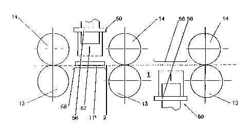
Fig. 1l represents a possible embodiment of a pneumatic intermittent beater 50
that is mounted
between two upper rollers 14 that are not illustrated in the figure. Fig.11 is
a section through a
plant normal to the direction of transportation. The printed circuit boards
PCB are guided in the
conveying plane 2. The pneumatic intermittent beater 50 consists of a piston
with a controllable
valve 51, of a feed pipe for the compressed air 52 and of a drain pipe for the
compressed air 53.
The piston with the controllable valve 51 is rigidly connected to an
oscillator 56 serving as a
transmission means. The pneumatic intermittent beater 50 is arranged in close
proximity to the
conveying plane 2 and is hung on a device 54 by means of springs 55.
The level 60 of the liquid for treatment is situated above the conveying plane
2 and the oscillator
5G so that the printed circuit boards PCB and the oscillator 56 of the
pneumatic intermittent
beater 50 are completely immersed into the liquid for treatment.
The compressed air, which is admitted by a valve into the piston, causes the
preferably heavy
piston to accelerate downward in the direction of the arrow 57 and generates
mechanical pulses
57 in the oscillator 56 on impinging on said oscillator 56, said pulses being
transmitted to the
printed circuit boards PCB in the conveying plane 2 through the liquid for
treatment.
Fig. 12 represents a further embodiment of the invention: printed circuit
boards PCB that are
conducted in the conveying plane 2 through the processing chamber 1 pass
through fan nozzles
70 between the feed rollers 13 and 14, said nozzles being provided with jet
chambers 71 with
nozzle apertures 72. Pneumatic intermittent beaters 50 communicate with the
jet chambers
7lvia oscillators 56 that transmit pulses 57 to the nozzles 70 so that the
liquid for treatment that
is delivered by the nozzles 70 to the surfaces of the printed circuit boards
PCB impinges on
them in pulsated jets. The nozzles 70 are arranged in such a manner that the
nozzle apertures 72
CA 02397078 2002-07-09
22
are located underneath the level 60 of the liquid in the chamber 1. For the
rest, the device
corresponds to the one illustrated in Fig.11 so that reference is made to that
description.
Fig. 13 shows another embodiment of the invention, this embodiment
constituting an
improvement of the arrangement represented in Fig. 12. Furthermore, in this
embodiment, the
principle already shown in the Figs. 7 and 7A - 7D for generating pulses is
realized. The reader
is referred to the description of the Figs. ? and 7A - 7D with regard to the
elements of the device
and to the corresponding reference numerals carried forward from said Figs.
In this case, the printed circuit boards PCB are conveyed past a preferably
solid metal plate 73
positioned at a distance of only a few millimeters {e.g., 1 - 3 mm) from the
conveying plane 2
and through which the pulses are transferred by way of the liquid for
treatment to the printed
circuit boards PCB. For this purpose, the metal plate 73 is arranged within
the liquid for
treatment together with an anvil 75. The metal plate 73 is preferably soldered
to the anvil 75.
The anvil 75 should at least in parts protrude from the liquid for treatment.
The two elements are
normally resting and are connected to the processing facility in a manner that
has not been
illustrated herein. The metal plate 73 extends over the entire width of the
conveying path so that
pulses may be transmitted onto the printed circuit boards PCB on the entire
width of the
conveying path.
Pulses are generated by a ratchet-like pulse generating means 30 that may be
configured in the
same manner as the pulse generating means in the Figs. 7 and 7A - 7D and that
functions in the
same way. By way of the lever 31 and the hammer 74 connected to said lever 31,
impacts are
transferred onto the anvil 75 and the metal plate 73 so that pulses may be
generated in the
printed circuit boards PCB.
CA 02397078 2002-07-09
23
Listing of reference numerals:
1 processing chamber
2 conveying plane
3 direction of transportation
4 entrance wall at the chamber 1
exit wall at the chamber 1
6 side walls of the chamber 1
7 floor of the chamber 1
8 lid of the chamber 1
9 feed pipe to the nozzles 10
nozzles
11 entrance slot
12 exit slot
13 lower transportation means /feed rollers
13' lower transportation means/feed roller at the entrance slot 11
13" lower transportation means/feed roller at the exit slot 12
14 upper transportation means/feed rollers
14' upper transportation means/feed roller at the entrance slot 11
14" upper transportation means/feed roller at the exit slot 12
hollow space in the rollers 13, 14
21 pulse generating means, body, metal rod
22 projection, stumble strip
23 inner lining, ferromagnetic core, steel cylinder, rectangular tube in the
rollers 13,14, bar
magnet
24 direction of rotation of the rollers 13,14
inner edge in the rectangular tube 23
26 axis of the upper roller 14
27 axis of the lower roller 13
wheel provided with projections 36, ratchet
31 pulse generating means, beater, striking pin
CA 02397078 2002-07-09
24
32 bearing for the beater 31
33 spring at the beater 31
34 fastening part for the beater 31
35 mounting part for fastening the beater 31
36 projection, teeth at the beater 31
37 space between the teeth 36
38 body of the wheel, the ratchet 30
40 pulse generating means, electromagnet
41 coil of the electromagnet 40
42 elastic rest for accommodating the lower roller 13
43 stop for the upper roller 14
44 electric feed lines for the electromagnet 40
45 pole piece of the electromagnet 40
50 pulse generating means, pneumatic intermittent beater
51 piston with controllable valve
52 feed line for delivering compressed air to the pneumatic intermittent
beater 50
S3 drain pipe for carrying the compressed air away from the pneumatic
intermittent beater
54 suspension device for the pneumatic intermittent beater 50
springs on the suspension device 54
56 pulse generating means, oscillator at the pneumatic intermittent beater 50
57 pulses
58 reflecting means
level of the liquid for treatment
fan nozzles
71 jet chambers of the fan nozzles 70
72 nozzle apertures in the fan nozzles 70
73 metal plate
74 hammer
anvil