Note: Descriptions are shown in the official language in which they were submitted.
CA 02397079 2002-07-09
WO Ol/51839 PCT/DKO1/00002
1
Armoured, flexible pipe and use of same
The present invention concerns a flexible, armoured pipe which comprises
an inner liner with an inner and an outer surface, said outer surface being
surrounded by at least one inner and one outer reinforcement layer.
The invention also concerns the use of the pipe.
Such a pipe comprises an inner liner which forms a barrier against the
outflow of the liquid which flows through the pipe, said inner liner being
surrounded by a cavity in which a number of helically-wound, pressure-
reinforcement profiles are arranged, and where the individual pressure-
reinforcement profiles are wholly or partly surrounded by a free volume.
The pressure-reinforcement layer is not chemically bound to the inner liner,
but can move freely in relation to this, which ensures the flexibility of the
pipe.
Since the individual elements of the pipe are not chemically bound to one
another, this type of pipe is referred to in the literature as "unbonded".
Outside the pressure-reinforcement layer a plurality of traction-
reinforcement profiles are wound, the individual traction-reinforcement
profiles being wholly or partly surrounded by a free volume.
The above-mentioned type of pipe is used, among other things, for the
transport of oil and gas in deep waters or waters of varying depth. The
above-mentioned construction is especially suitable for the transport of oil
from offshore oil wells to installations on the surface of the sea where the
oil
is refined, or is sent further for processing.
WO 01/51839 CA 02397079 2002-07-09 pCT/DK01/00002
2
The construction of pipes with functions similar to the above is known, for
example, from JP3265781, which describes a reinforced flexible pipe where
the whole of the reinforcement is surrounded by an impermeable sheath
which prevents the ingress of fluids from the surroundings to the
reinforcement layer of the pipe, which provides the advantage that the pipe
reinforcement can absorb forces stemming both from inner as well as outer
pressure.
Conversely, US Patent No. 4,402,346 describes a pipe where the
reinforcement is surrounded by a permeable outer sheath, which provides
the advantage that aggressive gases which are diffused out through the
inner liner do not accumulate in the reinforcement layer.
However, a problem in connection with this type of pipe is that fluids will
permeate through the outer sheath and exercise a hydrostatic pressure in
the reinforcement layer and herewith on the inner liner, corresponding to
the pressure of the surroundings, whereby the surrounding pressure will be
able to crush the inner liner. a
Finally, from NO B 301733 a flexible pipe is known, which is surrounded by
an impermeable outer sheath, where between the pressure reinforcement
and the traction reinforcement there is an impermeable anti-friction capsule,
the function of which is to provide an electrical insulation (out of regard
for
the avoidance of galvanic corrosion) between the traction and the pressure
reinforcement.
Since the outer sheath of the flexible pipe described in NO B 301733 is
impermeable, the transport of fluids between the outer reinforcement layer
and the surroundings is prevented. This impermeability is critical if the
outer
reinforcement is made of a material which is not resistant to the fluids which
CA 02397079 2006-09-20
3
may be diffused out into the outer reinforcement layer from the inside of the
pipe.
It is the object of this invention to provide a pipe where the resistance
against crushing of the inner liner as a consequence of the pressure of the
surroundings is maintained, while at the same time the traction
reinforcement of the pipe is protected against the damaging effect of gases,
which emanate through the inner liner of the pipe.
The present invention provides flexible, armoured pipe comprising an inner
layer
which forms a barrier against outflow of fluid which flows through the pipe
and
which has an inner and an outer surface, the outer surface being surrounded by
at least an inner and an outer reinforcement layer. The at least one inner
reinforcement layer is separated from the at least one outer reinforcement
layer
by an impermeable membrane. At least one outer reinforcement layer also
includes at least one traction reinforcement layer which mainly absorbs axial
forces and is wholly or partly in contact with the surrounding environment.
By preventing the migration of fluids from the pipe's outer layer into the
pressure reinforcement layer, it is ensured that the pressure reinforcement
can absorb forces from inner pressure as well as from outer pressure
stemming from the surroundings.
In other words, counteraction is provided against the effect of the
hydrostatic pressure on the inner liner.
CA 02397079 2007-11-13
" =
4
Like the pressure reinforcement, the traction reinforcement is formed by the
winding of profiles, though here with a relatively low angle in relation to
the
longitudinal axis of the pipe, so that these profiles mainly absorb axial
forces.
On the outside of the traction reinforcement layer a permeable layer may be
applied, which allows passage partly of fluids which are transported inside
the
pipe and partly of fluids which exist outside the pipe.
In this way it is ensured that the concentration of injurious elements which
emanate from the inside of the pipe out into the traction reinforcement is at
all times lower than the highest permissible limit.
If the pipe is used in water, an effective cooling of the traction
reinforcement
layer is also ensured, so that this is not damaged as a consequence of
being heated by the fluid, which is transported through the pipe.
Finally, the traction reinforcement layer is protected against mechanical
influences.
Expedient embodiments of the, invention are disclosed in the dependent
claims.
As mentioned, the invention also concems an application of the pipe.
The invention will now be explained in more detail with reference to an
example
embodiment shown in the drawing, in that
WO 01/51839 CA 02397079 2002-07-09 pCT/DK01/00002
fig. 1 shows the construction of a commonly-known pipe partly in
section, vihile
fig. 2 shows a section through the wall of a pipe according to the
5 invention.
In fig. 1, the reference number 3 indicates an inner liner, which surrounds a
carcass 1, the object of which is to prevent the collapse of the inner liner 3
if
the pressure difference between its outer and inner side exceeds that
pressure which the inner liner 3 itself can tolerate.
The carcass 1 consists of a metal band 2 which is wound in a helical
manner so that it forms an inner pipe, and where the metal band is formed
with lobes which engage with each other during the winding-up, so that they
lock the individual windings in the helically wound band to each other in
such a way that the carcass 1 can be bent out of its longitudinal direction.
In that the carcass 1 itself is not imp'ermeable, the surrounding inner liner
3
serves wholly or partly to prevent fluid or gas from flowing from the inside
of
the pipe out into the inner reinforcement layer.
It is obvious that although it is shown here as a separate unit, the liner 3
can be a more or less integrated part of the above-mentioned carcass.
The metal band 2, which constitutes the carcass 1, is most frequently of
stainless steel, although the use of other metal alloys and pure metals can
be envisaged. The liner 3 can be made of a thermoplastic material, most
often selected from among polyamides, polyolefins, polyketones or
polyvinylidene fluoride, but many other materials can be used.
WO 01/51839 CA 02397079 2002-07-09 pCT/DK01/00002
6
It should be noted that in certain situations pipes could appear, which do
not contain a carcass.
The liner can be built up either as one layer or as several polymeric layers
with identical or different characteristics, which are extruded on the outside
of one another.
Hereafter, one or several layers of reinforcement profiles 5,6 are wound in a
helical manner on the outside of the inner liner 3, which reinforcement
profiles form windings with a very small pitch in relation to the longitudinal
direction of the pipe. These reinforcement profiles constitute the pipe's
pressure reinforcement.
The windings create great resistance against the liner 3 being crushed as a
consequence of a high positive pressure difference between the inside and
the outside of the inner liner.
If the pressure reinforcement layer 5,6 is shielded from the outer
environment, this will also protect the inner liner 3 against crushing as a
result of the hydrostatic pressure of the surroundings.
In order to ensure the layer's flexibility, this is configured so that it
contains
a certain free volume. In this way, the flexibility of the layer is ensured.
As can be seen from the figure, the profiles which constitute the pressure
reinforcement 5,6 consist of C-shaped profiles, these profiles being oriented
in such a manner that two layers of windings, which are wound around the
liner 3 in the same direction, engage each other.
However, other types of profiles, such as e.g. Z-shaped and T-shaped
profiles are often used for the same purpose.
WO 01/51839 CA 02397079 2002-07-09 pCT/DK01/00002
7
Many materials can be used for the manufacture of the profiles, which
constitute the pressure reinforcement, but use is most often made of
metals, preferably carbon steel.
In that pressure build-up and pollution can arise in this layer as a
consequence of diffusion of gas into it, use is made of conventional
methods described in the literature in order to ensure cleaning and removal
of condensation and gases, which have accumulated in this layer.
On the outside of the pressure reinforcement 5,6 a further reinforcement
layer 7,8 is arranged, which consists of one or several layers of profiles 7,8
or bands which are wound in a helical manner with a considerably greater
pitch than the above-mentioned pressure reinforcement profiles 5,6.
In the following, these profiles or bands are referred to as traction
reinforcement. By winding with a high pitch, it is ensured that the traction
reinforcement can effectively absorb the tractive forces in the longitudinal
direction of the pipe, which can arise during the laying-out or operation of
the pipe.
Out of regard for ensuring the flexibility of the pipe, the individual
traction
reinforcement elements are normally disposed so that there is clearance
between their windings.
Between the above-mentioned traction reinforcement elements, there can
also be placed layers of a material with the object of preventing tearing or
wear between adjoining traction reinforcement elements when the pipes are
bent.
The traction reinforcement elements 7,8 can be made of many materials,
merely providing that these possess the necessary tensile strength to
WO 01/51839 CA 02397079 2002-07-09 pCT/DK01/00002
8
ensure the function of the pipe. However, in that the profiles 7,8 are
essentially exposed to the surrounding environment, it is an advantage that
these are selected from among materials, which are not damaged by the
surrounding environment.
For use in seawater, traction reinforcement elements made of fibre-
reinforced polymers or alloys based on titanium are especially suitable. In a
specially preferred embodiment, the traction reinforcement elements
mentioned here are pre-formed before the winding, so that after being
wound they lie substantially free of mechanical stresses in the pipe.
In one embodiment, the individual profiles are coated with an elastic
material before being applied, the object of which is to reduce the effect of
sudden point-loading arising from blows on the outer side of the pipe.
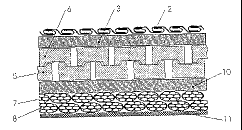
The reference numbers in fig. 2, which are also used in fig. 1, indicate
construction details, which are identical for the two figures. Therefore,
these
will not be discussed in detail.
In comparison with the pipe in fig. 1, around the pressure reinforcement
layer 5,6 on the pipe according to fig. 2 an impermeable membrane 10 is
applied, the object of which is to prevent the ingress of fluids from the
pipe's
surroundings to the pressure reinforcement layer 5,6. This function is
important, in that all layers outside the centremost sheath are substantially
exposed to the surrounding environment. Therefore, the impermeable
membrane 10 must function as a transport barrier between the
surroundings and the pressure reinforcement. The impermeable membrane
is characteristic in that it is produced from an extruded thermoplastic
material, and is essentially impervious to fluids.
WO 01/51839 CA 02397079 2002-07-09 pCT/DK01/00002
9
Preferred types of plastics are to be found in the group of polyamides,
polyolefins or polyketones, although many other types of plastic and
mixtures hereof will also be suitable. The membrane 10 can be built up
either as one layer or as several polymeric layers with identical or different
characteristics which are extruded around one another.
In order to ensure that the traction reinforcement elements 7,8 are held in
place, and also for the protection of these elements, an outer layer 11 can
be applied outermost on the pipe. This outer layer is easily permeated by
the surrounding environment, so that it does not to any great degree
prevent contact between the surrounding environment and the traction
reinforcement elements.
The outer layer can expediently be produced from an extruded
thermoplastic material, which is perforated, either during or after the
production.
In a second preferred embodiment, the sheath is made of a plaited
material, e.g. a band made of aramide strips, which are embedded in a
thermoplastic matrix.
It is obvious that the present invention can be used in ways other than
those disclosed in the above, in that there is great freedom for use of the
principles of the invention in other connections within the scope of the
patent claims.