Note: Descriptions are shown in the official language in which they were submitted.
CA 02397230 2002-07-11
WO 01/56618 PCT/GBOO/04873
Sterilizer Test Device
This invention relates to a sterilizer test device.
Almost all hospitals in the western world are provided with
sterilizing equipment to ensure the sterility of instruments and
devices which may come into contact with humans. The risks and
dangers of conducting operative procedures on living creatures
including animals and humans with non-sterile equipment and in
non-sterile surroundings is well documented. In an environment in
which patients expect to be treated successfully and in a sterile
manner, the requirement for effective sterilization is an essential
one, and devices have been developed to test the efficacy of
sterilizers and sterilization.
Although the following description relates exclusively to the use of
sterilizer test devices in hospitals, the device of the present
invention has much wider application, and specifically can be used
in bench top sterilizers such as might be provided in community
healthcare and animal care clinics for the sterilization of utensils,
dressings, medical textiles and the like.
Modern sterilizers, many of which are in the form of high pressure
autoclaves, subject their contents to high temperature steam for a
predetermined period of time. The three fundamental parameters of
the sterilization process are accordingly time, temperature, and the
presence of steam. Effective sterilization can only be achieved if
there is steam contact with all parts of the load to be sterilized for
the correct period of time. Air trapped and entrained within the
load will prevent this necessary steam penetration. The
thermodynamic irregularities of air/water vapour mixtures, and the
necessarily hostile environment developed inside cabinet autoclaves
CA 02397230 2002-07-11
WO 01/56618 PCT/GBOO/04873
2
makes the monitoring of sterilization process difficult, and
therefore a simple visual indicator test was developed.
In the 1960s, the Bowie Dick test assessed whether the air removal
stage of the sterilization process was sufficient to ensure rapid and
even steam penetration to all parts of the load. The test involved
placing within the sterilizer a stack of towels approximately 11
inches high and having a cross-sectional area roughly approximating
to the size of an A4 sheet of paper. Within the stack at
approximately half height thereof, there was placed a sheet of paper
on one surface of which was applied a pattern of a chemical
indicator ink which was extremely sensitive to and changed colour
in the presence of high temperature steam. The test was performed
by simply placing the stack towels within the sterilizer, and
initiating a standard cycle of the sterilizer which would be carried
out on, for example a tray of surgical instruments, hospital bed
linen and the like, for a certain period of time, for example 3-4
minutes. On removal of the stack of towels, the indicator sheet was
inspected for a uniform colour change of the indicator over the
entire surface of the sheet, and if this was the case then the
sterilizer air removal stage was considered to be functioning
effectively.
It is well known that heat alone can provide effective sterilization,
however the rapid inactivation of microorganisms is significantly
faster in the presence of moist heat (steam). For example, effective
sterilization can be achieved by subjecting material to dry heat at
160 C for 1 hour, whereas the same level of sterilization can be
achieved by introducing steam at 130 for 3 minutes.
In the Bowie Dick test, the towels were used as what is now termed
a"porous load". Such loads are deemed one of the most difficult to
assess the penetration characteristics of the steam or to provide
CA 02397230 2002-07-11
WO 01/56618 PCT/GBOO/04873
3
some resistance to the steam as it progresses towards the indicator
sheet. The rationale behind this test is that if the steam can
penetrate the porous load to adequately change the colour of the
indicator sheet, then any medical device, textile or the like having a
lower resistance to steam penetration will be effectively sterilized.
A current modification of the original Bowie & Dick test is the use
of a disposable or reusable barrier surrounding a chemical indicator
sheet. This is calibrated to perform in a similar manner to the
original Bowie & Dick towel pack with a chemical indicator
inserted. After the pack has been subjected to a conventional
sterilization, the indicator sheet is removed and inspected for a
uniform colour change over the entire surface area of the sheet,
which is indicative of the effective operation of the sterilizer air
removal stage.
A disadvantage with this method of testing is that the product once
used must be discarded. When it is considered that millions of tests
are conducted annually in hospitals and other sterile environments
around the world, the cost saving to be made by a reusable device
may be considerable.
One alternative currently available to the disposable test pack
described above is a device which comprises a coiled narrow lumen
approximately 2-3 metres in length and having a diameter of
approximately 2mm, open at one end and connected at its alternate
end to a small accessible capsule into which a chemical indicator can
be placed. In use, the coiled lumen is placed inside the sterilizer
whereafter the sterilization procedure is initiated during which the
steam gradually progresses along the interior of the lumen until
reaching the capsule into which the lumen passes. The efficacy of
steam penetration can be assessed based on the chemical indicator
CA 02397230 2002-07-11
WO 01/56618 PCT/GBOO/04873
4
result. Thereafter, the device may be reused, using a new indicator
in the capsule.
The length and narrow entrance of the lumen open end render the
lumen arguably not analogous to a porous load for reasons of mass,
directional sensitivity, and physical shape etc.
Hence there are a number of serious disadvantages associated with
the lumen device. Firstly, the history of use of the device cannot
easily be established and although the chemical indicator may be
replaced before each use of the device, there is no guarantee that
the device was not previously mistreated or was not fully prepared
for the next use by the previous user. It is to be borne in mind that
in a busy hospital, the device may simply left proximate the
sterilizer for use by any of the numerous staff who have cause to
use same.
Secondly, there is a risk that the openable capsule is not securely
closed. This would allow the steam an easier path to the open end
of the indicator tube within the capsule, and thus the device could
give the false indication that the sterilizer was functioning
satisfactorily.
Thirdly, steam has a propensity to condense on the external, and
more importantly the internal walls of the lumen. If sufficient steam
condenses of the internal wall of the lumen along the path to the
capsule, there may be a plug of condensate which could prevent the
steam from reaching the open ended indicator tube within the
capsule.
Fourthly, the problem of condensation is also apparent when the
lumen is removed after the test has been completed, and in some
cases there can be a fine mist of water vapour or a fluid bubble
CA 02397230 2002-07-11
WO 01/56618 PCT/GBOO/04873
retained within the lumen. When a subsequent test is conducted, the
lumen is heated in the sterilizer and by means of conduction, this
water vapour could also heat and be urged towards the chemical
indicator within the capsule. The device could in this circumstance
also provide false results.
Finally, it is contended by many of those in the art that the single
narrow opening through which the steam passes before travelling
the length of said lumen is too directionally sensitive, that is it does
not provide a fair average of the steam penetration characteristics
within the sterilization chamber.
Examples of directionally sensitive sterilization test devices are
shown in consecutive published patent applications
PCT/DE94/00687, PCT/DE94/00688, PCT/DE94/00689, all to
Van Dijk Medezintechnik GmbH. All these documents disclose
essentially cylindrical hollow test devices, one end of which is
closed off from the atmosphere by means of a plug or stopper
proximate to which a chemical indicator means is positioned in an
inner chamber of the device, the alternate open end of the devices
having different inserts provided therein to provide a penetrable
barrier through which steam must pass to interact with the chemical
indicator within the device.
In particular, PCT/DE94/00687 discloses the use of a threaded
plug which is screwed into the open end of the device but which has
threads of marginally lesser diameter than those provided internally
of the device such that a helical channel is defined between the
threads of the plug and those of the device. This device is
effectively similar to the lumen device disclosed above, with the
exception that a fixed helical path leads from the exterior of the
device to the chemical indicator, as opposed to the spiral path along
which the steam can travel within the lumen.
CA 02397230 2002-07-11
WO 01/56618 PCT/GBOO/04873
6
PCT/DE94/00688 discloses the use of an array of capillaries
provided between the inner chamber of the device in which the
indicator is located and the alternate open end of the device from
which the steam within a sterilizer can penetrate, and
PCT/DE94/00689 discloses the use of a porous material plug
through which the steam can penetrate towards the indicator located
in the inner chamber of the device. Neither of these latter two
patent applications is specifically directed towards the use of a so-
called "tortuous path" such as is provided by the helical path
disclosed in PCT/DE94/00687 or the spiral path along which the
steam travels in the lumen of the abovementioned current devices,
whereas PCT/DE94/00687 does not consider the use of a so-called
"porous load".
Additionally, all the devices disclosed in the abovementioned patent
applications are directionally sensitive in that steam can only begin
to penetrate either the tortuous path or the porous load (or
equivalent load) from one particular side, and furthermore only on
one particular surface of the device. It is to be mentioned that the
conditions within autoclave units in general are extreme and non-
uniform, and it is possible that the directional sensitivity, which
term is used to describe the generally linear path along which the
steam or other sterilant travels before coming into contact with the
indicator, of such devices can result in the device producing false
results.
It is an object of the present invention to provide a sterilizer test
device which at least mitigates if not eradicates the disadvantages of
the prior art devices, and which is furthermore reusable and
combines the advantageous qualities of the devices mentioned.
CA 02397230 2002-07-11
WO 01/56618 PCT/GBOO/04873
7
According to the present invention there is provided a sterilizer test
device comprising a pair of bodies releasably and sealably connected
together defining an internal primary chamber within the device to
which access is gained by disconnecting said bodies, at least one of
said bodies being essentially comprised of a porous element which
allows penetration of steam therethrough and into said primary
chamber, indicator means being provided between said bodies at
some location within the primary chamber, said indicator means
having a characteristic which changes while in the presence of steam
and temperature after a predetermined time, characterised in that
said porous element has one or more external surfaces through
which steam can penetrate in a plurality of different directions.
Preferably intermediate tortuous path means is additionally provided
internally of the device and sealingly divides the primary chamber
into two secondary chambers, a first secondary chamber being
defined between the tortuous path means and an inner surface of
said at least one body through which steam having permeated said
body emerges, and a second secondary chamber being defined to the
alternate side of said tortuous path means from the first secondary
chamber and having the indicator means disposed therein, said
steam being constrained to flow into and around said tortuous path
means before emerging into the second secondary chamber and
thence coming into contact with the indicator means.
Preferably the said at least one body is provided with a substantially
arcuate outer surface. In one embodiment, the said at least one body
is preferably cylindrical.
Most preferably, the outer surface of - the porous body is
substantially continuous around at least one axis of the device.
CA 02397230 2002-07-11
WO 01/56618 PCT/GBOO/04873
8
It is most preferable that the two bodies connected together to form
the device have a predetermined degree of porosity, and
furthermore it is preferable that each of said two bodies is
substantially hemispherical.
It is yet further preferable that at least one of the bodies is provided
internally with a cavernous recess to increase the effective volume
of the primary chamber.
It is further preferable that the porous bodies are manufactured
from a sintered polypropylene material, which has the advantage
that its porosity can be varied according to requirements of a
particular device, and also that it can be formed in any desired
shape. In an alternative embodiment, the porous bodies are
manufactured from a spun bonded polymer material, but the
manufacturing process for such materials is limited in that only
articles having certain geometric shapes (such as a cylinder) can be
produced because of the manner in which the polymeric material is
spun.
It is yet further preferable that apertured diaphragm means is
provided internally of the primary chamber substantially across the
base of one of the said bodies thus defining a tertiary chamber with
the surfaces of the cavernous recess in which steam having
permeated the porous element from a plurality of different
directions can collect before passing through said aperture into
either the remainder of the primary chamber or the first secondary
chamber.
It is also to be mentioned that such an apertured diaphragm could
be used to sealingly divide either the first or second secondary
chamber and thus define first and second tertiary chambers from
said secondary chambers, and that two apertured diaphragms could
CA 02397230 2002-07-11
WO 01/56618 PCT/GBOO/04873
9
be used to divide both the first and second secondary chambers as
desired.
The division of the internal primary chamber into secondary and
tertiary chambers has been shown experimentally to improve the
overall performance of the sterilizer text device as a whole. Not
wishing to be bound by theory, it is believed that this enhancement
of performance is achieved because of the facility for steam to
collect in the volume of the secondary and tertiary chambers in use
which removes the effects on performance of the traditionally
cyclical and intermittent operation of modern sterilizers, i.e. the
alternate drawing of a vacuum and the introduction of steam into
the sterilizer during use to substantially eliminate air.
In a further aspect of the invention there is provided a tortuous
path means for use in a sterilizer test device of the type described
above, said means comprising at least two substantially planar
components having an outer surface and an inner surface separated
by their thickness, said components being releasably connected
together to bring their respective inner surfaces proximate one
another, one or other or both of said components being provided
with patterned grooved means on their inner surfaces following a
labyrinthine, spiral or other tortuous path on said surface, one of
said components being provided with an entry port leading from an
outer surface of said component through the thickness thereof and
opening at a particular location in said grooved means, characterised
in that an intermediate member is sandwiched between the two
components to sealingly close said grooved means and define a
tortuous channel to at least one side of said intermediate member.
Preferably an exit port is also provided to allow fluid to escape from
a particular location in the grooved means, or alternatively there is
CA 02397230 2002-07-11
WO 01/56618 PCT/GBOO/04873
provided a recess in said inner surface of one of said components in
which indication means as described above can be deposited.
Preferably the intermediate member is compressible to ensure
sealing formation of said channel.
Preferably grooved means are provided on the inner surfaces of
both components and the sandwiching of the intermediate member
forms channels with each of said grooved means on either side of
said member.
In a most preferred embodiment the components are hingedly
connected over at a portion of their respective edges.
It is also preferable that the entry port of one component opens
into the grooved means on the inner surface thereof proximate one
end of said grooved means, and also that the exit port provided on
the alternate component opens into the said grooved means in that
component proximate one end thereof.
Most preferably, the intermediate member is secured to the hinged
connection of the two components which ensures the correct
positioning of said intermediate member when the said two
components are releasably connected together.
It is yet further preferable that the intermediate member is provided
with an aperture therein which links respective tortuous channels
defined by said intermediate member on either side thereof.
In a yet further preferable embodiment, a chamber is defined
internally of said tortuous path means in which steam can collect
prior to being urged along said tortuous path.
CA 02397230 2002-07-11
WO 01/56618 PCT/GBOO/04873
11
It will be immediately understood by those skilled in the art that the
provision of separable components having grooves brought together
during the connection of the components to define respective
channels with the intermediate compressible member allows for easy
cleaning and airing of the grooved means. Hence, the device
according to the invention can be both readily aired and cleaned
while nevertheless being re-usable.
When the tortuous path means are used in connection with the
sterilizer test device described above, the steam first permeates the
porous bodies which substantially constitute the device and then is
constrained to flow into a chamber of the device and thence
through the tortuous path means before emerging therefrom into a
further cavity in which is disposed the indicator means. The
particular indicator means used is not important, and the device can
be calibrated for use with a variety of different indicator types, such
as chemical, biochemical, biological. It is also foreseen by the
applicant that electronic sensing and detection apparatus may be
used in place of the indicator means to provide accurate data logs
on the characteristics of the atmosphere extant in the device in any
of the chambers defined therein as a function of the time after the
commencement of any particular sterilization sequence.
The fundamental advantages of the present invention are firstly that
the use of cylindrical or hemi-spherical porous bodies to form the
device allows steam to permeate into said bodies from any direction
as substantially the entire surface of these bodies are porous, and
secondly that the tortuous path means can be easily, simply, and
quickly opened up to allow for airing and drying of the tortuous
path. Thereafter both the test device and the tortuous path means
can be reused. Obviously a quadrangular porous body having two or
more of its external surfaces exposed to the steam to allow for
penetration thereof would function in a similar manner.
CA 02397230 2002-07-11
WO 01/56618 PCT/GBOO/04873
12
A specific embodiment of the invention is now given by way of
example with reference to the accompanying Figures wherein:
Figure 1 shows an exploded perspective view of a cylindrical test
device in accordance with the invention,
Figure 1A shows a perspective view of an apertured diaphragm
which may be used in conjunction with the invention, and
Figure 2 shows an exploded perspective view of a spherical test
device in accordance with a different embodiment of the invention.
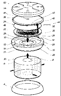
Referring firstly to Figure 1 there is shown a sterilizer test device
indicated generally at 2 comprising an annular base 4 which on
which the device stands when within a sterilizer, a cylindrical
porous body 6 having a cavernous bore 8 provided therein of a
depth less than that of the body 6 and chosen as required by the
particular application. Above the body 6, a number of different
components are provided to allow the device to function correctly.
The first of these is an annular cap 10 having formations 12, 14, 16,
18 which permit the rotating locking connection of other
components above said cap.
It will be seen from the diagram that the cap 10 is provided both
with a collar 20 which is chamfered around its outer surface shown
at 22 and is marginally greater in diameter than the body 6 over
which it is disposed. An annular inner surface 24 is provided at
approximately the median of the depth of the cap, and above and
around the periphery of said surface 24 there is provided an annular
skirt 26 which defines a circular recess with the said surface 24. An
aperture 28 allows steam which has permeated through the porous
CA 02397230 2002-07-11
WO 01/56618 PCT/GBOO/04873
13
body 6 to pass from the upper surface 30 thereof and from within
the cavity 8 through the cap 10.
The apertured diaphragm 25 may be sealingly disposed either on the
inner surface of the body 6 over the cavernous bore 8 or in the
aperture 28 so that a tertiary chamber is defined by said diaphragm
and said cavernous bore internally of the body, as this has
experimentally shown to improve the performance of the device,
that is to more accurately determine if a particular sterilizer under
test is efficacious.
In accordance with the invention there is provided a tortuous path
device consisting of three components 32, 34, 36 which are hingedly
connected together around their circumferences at hinge means 38,
40, 42 respectively. Specifically, the hinge means 38 is a protrusion,
40 is an aperture of marginally greater size than said protrusion and
through which said protrusion is fed before locating in a recess 42
in the component 36 in which it is pinned by means of rod 44.
With specific regard to said components 32, 34, 36, the first and
third components 32, 36 are substantially planar and provided with
spiral grooves 46 in one surface (only shown in respect of
component 32). The second component 34 is an intermediate
component ideally of a compressible material which is sandwiched
between components 32, 36 on releasably connecting same together
and ideally sealingly forms spiral channels with the said grooves
provided in the surfaces of the first and third components on either
side thereof.
The first and third components 32, 36 are provided with apertures
(one of which is shown at 48 in the component 36) at their centres
which form entry and exit ports to the spiral channels formed
between said components. The intermediate component 34 is
CA 02397230 2002-07-11
WO 01/56618 PCT/GBOO/04873
14
additionally provided with an aperture 50 which allows fluid
communication between the channel formed in the component 32
on one side of component 34 and channel formed in component 36.
Thus the fluid enters the spiral channel formed in the first
component through the aperture in said component 32 at its centre,
and is subsequently constrained to spiral outwardly from said centre
until reaching the aperture 50 (which is ideally located at the end of
the spiral groove 46). The fluid can then move through the aperture
50 and into the second spiral channel and wherein it is constrained
to spiral inwardly towards the aperture 48 from which it ultimately
emerges.
The entire arrangement of the tortuous path device (32, 34, 36) is
received in the upper recess defined in the cap 10 by the surface 24
and its peripherally surrounding skirt 26 and optionally locked
therein behind suitable flanges provided on the skirt 26. As the
device 2 is assembled, the pre-assembled tortuous device (32, 34,
36) may be simply dropped into said recess and rotated by means of
thumb indentations (not shown) provided on the upper surface of
component 38.
Once secured in place, an indicator (not shown or described in this
application as being considered beyond the scope hereof) is
positioned above the aperture 48, and a lid 52 having depending
skirt 54 is secured to the device by interengagement of formations
(not shown) provided on the inner surface of said skirt 54 with the
formations 12, 14, 16, 18 provided on the cap 10. The device is then
placed in a sterilizer which is then activated, and after a
conventional sterilization operation is complete the device is
removed and opened for inspection of the indicator.
It is to be mentioned that the device may be inverted, the base 4
dispensed with, and the lid 52 may be suitably designed to function
CA 02397230 2002-07-11
WO 01/56618 PCT/GBOO/04873
as a base having an inner surface in which an indicator may be
disposed. In terms of the wording of the claims appended hereto,
the primary chamber internally of the device is defined by the
cavernous bore 8 and the inner surface of said lid 52 through the
aperture 28. This chamber is sealingly divided by the interposing of
the tortuous path means (32, 34, 36) on either side of which are
defined first (on the side of the cavernous bore 8) and secondary
(on the side of the lid 52 inner surface) chambers. The first
secondary chamber may again be divided by the interposing of the
apertured diaphragm 25 as previously mentioned so that a tertiary
chamber is defined within the body 6 by said cavernous bore 8 and
said diaphragm.
It is also to be mentioned that the device described with reference
to Figure 1 can be used as a sterilizer test device without the
tortuous path means described above. An indicator may simply be
placed on the annular surface 24 or within the lid 52 to which steam
can gain access after having first permeated the porous body 6.
Additionally the configuration of the device 2 is adapted to be
further modified so that the porous body can be removed leaving
only the base 4, cap 10, tortuous path means (32, 34, 36) and lid 52.
However, use of the complete device having both porous body and
tortuous path means is preferred.
Referring now to figure 2 there is shown a modified configuration
of sterilizer test device 100. The device comprises of a tortuous
path device (32, 34, 36) as hereinbefore described disposed
internally of the device, and two hemispherical porous bodies 102,
104. Body 104 is provided internally with a cavity 106 in which
steam may collect, and the portions of both bodies 102 proximate
CA 02397230 2002-07-11
WO 01/56618 PCT/GBOO/04873
16
their diametral planes are received in the hingedly connectable skirt
members 108, 110 having hinge formations shown at 112, 114.
As with the embodiment shown in Figure 1, a suitably sized
apertured diaphragm may be used to define a chamber with said
cavity 106 as previously discussed.
The skirt member 108 is provided with a plurality of slots 116, 118
through which steam emerging from the planar surface 120 of body
102 can pass. When assembled together, the configuration is such
that steam permeating through the body 102 passes to the outside of
the tortuous path device and towards and into the cavity 106
without coming into contact with the indicator (not shown) which is
disposed between the outer surface of the component 32 and the
rear surface 122 of the cap 108. The disposition of said indicator,
possibly within a recess defined in said rear surface 122, and the
clamping arrangement of the two caps on the tortuous path device
(32, 34, 36) thereover ensures that steam cannot adversely affect the
indicator such that the device would give rise to false results.
In a similar manner to the operation of the device shown in Figure
1, the device 100 can be easily and quickly opened and the tortuous
path device released from over the indicator which can then be
inspected to ensure that a sterilizer is functioning correctly.
Additionally, the tortuous path device can be removed quickly, and
opened for drying and cleaning.
It is to be mentioned that the various arrows provided on the
diagrams are indicative of the possible flow of steam from outside
the devices and the particular flow paths possible inside said device.
It is most important to note that both the devices disclosed herein
are both reusable and "directionless" in that steam drawn towards
the devices when inside an operative sterilizer can permeate through
CA 02397230 2002-07-11
WO 01/56618 PCT/GBOO/04873
17
the porous body as soon as it comes into contact therewith. This is
in sharp distinction to the currently available devices which are
either not re-usable or which although being of similar size and
shape to the devices described herein, generally provide only a few
discrete ports through which access to a porous medium is
contained. Such devices are heavily directional, and therefore
disadvantaged in comparison to the present invention.