Note: Descriptions are shown in the official language in which they were submitted.
CA 02397536 2005-12-20
WO 01/54216 PCT/IL/00055
- 1 -
FUEL CELL WITH PROTON CONDUCTING MEMBRANE
FIELD OF THE INVENTION
This invention relates to an electric cell that converts the chemical energy
obtained in a fuel oxidation reaction directly into electric energy in a
continuous
process. More specifically the invention relates to fuel cells.
BACKGROUND OF THE INVENTION
Fuel cells are often described as continuously operating batteries or as
electrochemical engines. Fuel cells utilize an external supply of fuel and
oxygen (or
air) and produce power continuously, as long as the fuel and oxygen supply is
maintained.
The most classic fuel cell is the H2/02 fuel cell of the direct or indirect
type,
wherein hydrogen is oxidized to form H3O+ at the anode and oxygen is reduced
to
water at the cathode. In the direct type, hydrogen and oxygen are used as
such, the fuel
being produced in independent installations. The indirect type employs a
hydrogen-
generating unit, which can use as raw material a wide variety of fuels.
Another type of fuel cell is the organic fuel cell. In a direct oxidation cell
an
aqueous solution of an organic fuel such as methanol, formaldehyde or formic
acid, is
directly fed into the fuel cell without any previous chemical modification,
where the
fuel is oxidized at the anode, and oxygen is reduced to water at the cathode.
A major distinguishing characteristic of different fuel cells is in the
electrolyte
used. NASA's Jet Prepulsion Laboratory (JPL) developed a direct liquid-feed
cell
using a solid membrane electrolyte. A detailed description of JPL's fuel cells
can be
found, for example, in U.S. Pat. Nos. 5,599,638 and 5,773,162. These fuel
cells
operate without any acid electrolyte and comprise solid electrolyte membranes
fabricated from proton-exchange materials, especially NafionTM (manufactured
by
DuPont). When methanol is used as the fuel, the electro-oxidation of methanol
at the
anode can be represented by:
CH3OH+H2O'CO2+6H++6e,
CA 02397536 2005-12-20
WO 01/54216 PCT/IL/00055
- 2 -
and the electro-reduction of oxygen at the cathode can be represented by:
O2+4H++4e--2H2O.
Protons generated at the anode are transported directly across the electrolyte
membrane to the cathode. A flow of current is sustained by a flow of ions
through the
cell and electrons through the external load.
SUMMARY OF THE INVENTION
The challenge in fuel cell development for practical applications is to
improve
the economics through the use of low-cost components with acceptable life and
performance.
Thus, the present invention provides by the first of its aspects a fuel cell
comprising an anode chamber including an anode and means for providing fuel to
the
anode, a cathode chamber including a cathode and means for providing oxygen to
the
cathode, and a solid electrolyte membrane disposed between said cathode and
said
anode, wherein said solid electrolyte membrane is a proton conducting membrane
having pores with a diameter, smaller than 30 nm, said membrane comprising:
(i) 5% to 60% by volume, preferably 8% to 30% by volume of an electrically
nonconductive inorganic powder having a good acid absorption capacity, said
powder
comprising nanosize particles;
(ii) 10% to 90% by volume, preferably 30% to 80% by volume of an acid or
aqueous acid solution; and
(iii) 5% to 50% by volume, preferably 12% to 40% by volume of a polymeric
binder that is chemically compatible with said acid, oxygen and said fuel.
Typically, when the fuel used is organic, it is provided as a fuel aqueous
solution.
The solid proton conducting membrane used in the fuel cells of the present
invention has been described in WO 99/44245. The polymeric binders used in
these
membranes may be selected from the group consisting of
poly(vinilydenfluoride),
CA 02397536 2005-12-20
WO 01/54216 PCT/IL/00055
- 3 -
poly(vinilydenfluoride)hexafluoropropylene, poly(tetrafluoroethylene),
poly(methyl
methacrylate), poly(sulfoneamide), poly(acrylamide), poly(vinylchloride),
acrylonitrile, poly(vinylfluoride), Kel FTM and any combinations thereof.
The inorganic nanosize powder used for preparing the solid proton conducting
membrane may be selected from the group consisting of Si02, Zr02, B203, Ti02,
A1203, hydroxides and oxy-hydroxydes of Ti, Al, B and Zr, and any combinations
thereof.
As described above, the proton conducting membrane used in the fuel cell of
the invention comprises, inter alia, an acid. Typically, the diameter of the
membrane
pores is smaller than 30 nm, preferably smaller than 3 nm, more preferably
smaller
than 1.5 nm. As opposed to the solid electrolyte membrane described for
example in
U.S. Pat. No. 5,599,638, wherein no acid is present in free form, the solid
electrolyte
membrane used in the fuel cell of present invention contains free acid
molecules
entrapped in the pores of the membrane. Alternatively, it may contain acid
molecules
bonded to the inorganic powder.
Thus, such a PCM comprises a matrix made of silica powder, preferably
nanopowder, bonded with an appropriate polymer binder described above, and
acid
molecules chemically bonded to the silica, thus reducing or avoiding the need
to insert
acid into the fuel solution. Other nanopowders can be used in a similar way.
According
to this option the acid, preferably sulfonic acid, is chemically bonded to the
inorganic
nanopowder directly or through an organic segment R selected from --(CH2)õ--, -
-
(CF2)õ-, --(CF2CH2)m -, where n is an integer from 1 to 10 and m is an integer
from 1
to 5, perfluoroaryl, polyfluoroaryl, perfluorostyrene, polyflouro styrene and
similar
segments where up to 50% of the hydrogen or fluorine atoms were replaced by
chlorine atoms.
A non limiting procedure to form sulfonic acid groups bonded to silica is
described hereinbelow: nano size silica powder is boiled in pure water for two
hours to
enrich the powder surface with OH groups. Than the hydrated powder is immersed
in a
solution of cloro, methoxy, or alkoxy organo sulfur silan of the type CH3COSR--
Si(OCH3)3 or CH3COSR--SiC13, where R is one of the organic segments listed
above.
CA 02397536 2005-12-20
WO 01/54216 PCT/IL/00055
- 4 -
The silan reacts with the surface OH groups of the silica powder to form up to
one
monolayer of the organic sulfur silan. Than the powder is oxidized by air and
the
thioacetate group is converted into a sulfonic acid group. This step is
described in the
following equation:
SiO2--R--S--C(O)CH3+O2-+SiO2--R--SO3H+2COz+H2O.
The obtained chemically bonded sulfonic acid is stable in strong acids at 90
C.
and, therefore, it may be used in the preparation of a PCM for fuel cell
applications,
instead of pristine SiO2.
The anode and the cathode comprise a catalyst layer and optionally also a
porous backing layer. A preferred catalyst used at the anode is for example
nano size
platinum-ruthenium powder, while preferred catalysts used at the cathode are
for
example nano size platinum powder and alloys thereof with non noble metals,
for
example Ni, Co, and Fe. In such alloys the ratio between platinum and the
metal (Pt:M
atomic ratio) is between about 1:3 to about 3:1.
A large variety of low vapor pressure acids that are compatible with the cell
hardware and with the catalysts at both electrodes may be used in accordance
with the
invention.
The backing layer is preferably made of carbon. This layer is porous and is
used for support and at the same time for making electrical contact between
the
housing and the catalyst powder, which by itself is connected to the membrane.
The means for circulating a fuel past the anode and for flowing oxygen or air
past the cathode include also means for withdrawing carbon dioxide, unused
fuel and
water from the anode side and for withdrawing unused oxygen and water from the
cathode side.
One advantage of the fuel cell according to the invention over current art
fuel
cells is that it uses a membrane that is easily wet. Thus, there is no need to
develop
special means for membrane humidification, as is the case in current art fuel
cells, as
evident, for instance, from U.S. Pat. No. 5,952,119 to Wilson, which states
that "one of
the primary challenges in attaining optimal perforrnance of polymer
electrolyte
CA 02397536 2005-12-20
WO 01/54216 PCT/IL/00055
- 5 -
membrane fuel cell is attaining effective hydration of the ionomeric membrane
structure". Wilson suggests solving this problem by applying a hydrophilic
wick to
wick liquid water to the membrane. As the fuel cell of the present invention
does not
show wetting difficulties, such a wick is saved, and the cell construction is
simplified.
According to one embodiment of the present invention, the fuel cell of the
invention. is a H2/02 fuel cell, wherein two sets of integrated flow channels
are
engraved in the cathode chamber or in the anode chamber. In one set of
channels of
this embodiment reactant gases are flowing, and in the other--the electrolyte
is
circulating.
According to yet another aspect of the present invention there is provided a
method for reconditioning a direct oxidation fuel cell, the method comprises
the steps
of:
(a) operating the cell at a reversed voltage of 0.6 to 1.3V for a period of
time T.
Preferably, the time period T is between 1 to 100 minutes. A longer period T
is
preferable as the cell ages or as it suffers a higher level of impurities.
Preferably, the voltage is between 0.6 and 1.3V.
The inventors applied this reconditioning procedure 10 times, each time for 1
to 30 minutes, during a 3500 hours operating period of a fuel cell and found
an
improvement of the cell voltage of 50 to 100 mV.
The invention also provides a method for preparing a catalyst layer for use in
a
fuel cell, said method comprising the steps of forming up to one monolayer of
a
catalyst on the surface of a nanosize inorganic powder, such monolayer serving
as a
nucleation site, forming additional one or more catalyst layers on the top of
said first
monolayer to obtain catalyst particles and subsequently binding the obtained
particles
to the carbon backing layer and/or to the proton conducting membrane.
According to another aspect of the present invention there is provided a
hybrid
power source comprising a liquid feed fuel cell according to the invention, a
DC to DC
converter and a rechargeable battery.
CA 02397536 2005-12-20
WO 01/54216 PCT/IL/00055
- 6 -
According to another aspect of the present invention there is provided a
device
for controlling the water return flow from the cathode side to the anode side
in a fuel
cell, comprising a water or fuel solution level sensor and air or oxygen
pressure control
unit placed in the cathode compartment, and a fuel cell comprising-such a
device.
According to another aspect of the present invention there is provided a
method for reducing crossover current in a fuel cell having an anode chamber
with an
anode and a fuel tank for providing said anode with fuel, a cathode chamber
with a
cathode and means for providing said cathode with oxygen in a given pressure,
a solid
electrolyte membrane disposed between said cathode and said anode, and a tank
for
water or fuel solution, an air or oxygen pressure control unit and a sensor
for sensing
the level fuel solution in said fuel tank and means for controlling said
pressure in
response to said level of water or fuel, comprising the steps of:
(a) sensing the level of the water or fuel in the water or fuel tank;
(b) controlling the air or oxygen gas pressure in the cathode chamber to
increase as the level of water or fuel solution sensed in step (a) decreases;
thus reducing the crossover current.
According to another aspect of the present invention there is provided a free
direct oxidation fuel cell having a low crossover current density, wherein the
fuel
solution tank is directly attached to the anode chamber, the fuel
concentration is
between 1% and 40% (w/w) and the ratio between the tank volume (in ml) and the
electrode area, in cm2 is between 3:1 and 30:1.
According to another aspect of the present invention there is provided an
orientation independent direct oxidation fuel cell system having
(a) an anode chamber with an anode, fuel inlet and gas outlet;
(b) a cathode chamber with a cathode and oxygen or air inlet;
(c) an electrolyte membrane disposed between the anode and the cathode; and
(d) a fuel tank connected to the anode chamber, wherein
CA 02397536 2005-12-20
WO 01/54216 PCT/IL/00055
- 7 -
i) said fuel tank being divided by a movable barrier into two parts, said
first
part of the fuel tank being capable of containing fuel or fuel solution and
connected to
the anode chamber, said second part of the fuel tank holding gas with pressure
greater
than atmospheric pressure or having a closable gas inlet;
ii) said gas outlet being closed with a gas permeable hydrophobic matrix;
said barrier being capable of directing fuel or fuel solution from the fuel
tank
to the anode chamber irrespective of the fuel cell orientation.
BRIEF DESCRIPTION OF THE DRAWINGS
In order to understand the invention and to see how it may be carried out in
practice, several embodiments will now be described, by way of non-limiting
example
only, with reference to the accompanying drawings, in which:
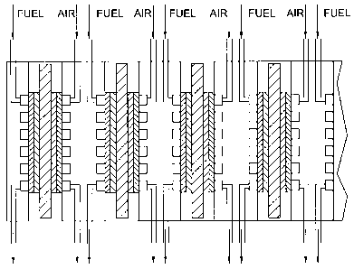
FIG. 1 shows a schematic representation of a multi-cell fuel system.
FIG. 2 shows an integrated gas--acid solution flow field system used in a
hydrogen/oxygen fuel cell.
FIG. 3 shows a graph illustrating polarization curves at different methanol
concentrations.
FIG. 4 shows a graph illustrating polarization curves for different acids.
FIG. 5 shows a graph illustrating the effect of additives on polarization
curves.
FIG. 6 shows a graph illustrating the relation between the pore size of PCMs
and temperature of hot press
FIG. 7 shows a graph illustrating three consecutive polarization curves (3M
H2SO4+1M MeOH at 65 C.).
FIG. 8 shows a schematic representation of a H2/02 fuel cell with integrated
gas-acid flow field.
CA 02397536 2005-12-20
WO 01/54216 PCT/IL/00055
- 8 -
FIG. 9 shows a graph illustrating a polarization curve for a Hz/Oz fuel ce11
(25 C., 1 psi H2 and 02 pressure).
FIG. 10 shows a graph illustrating the polarization curve of a cell operating
with a solution of 1M MeOH in 3M sulfuric acid.
FIG. 11 shows a schematic representation of a fuel cell which operates as a
primary battery. ,
FIG. 12 is a schematic illustration of an orientation independent hybrid power
source according to one embodiment of the present invention.
DETAILED DESCRIPTION
Several embodiments of the invention will be described and exemplified with
reference to the figures.
According to one aspect of the present invention there is provided an improved
fuel cell. The fuel cell to be improved by the invention includes an anode
chamber
including an anode and means for providing fuel to the anode, a cathode
chamber
including a cathode and means for providing oxygen to the cathode, and a solid
electrolyte membrane disposed between said cathode and said anode. Such fuel
cells
and their way of operation are well known in the art. The present invention
seeks to
improve prior art fuel cells by applying as an electrolyte membrane a proton
conducting membrane having pores with a diameter, smaller than 30 nm, said
membrane comprising:
(i) 5% to 60% by volume, preferably 8% to 30% by volume of an electrically
nonconductive inorganic powder having a good acid absorption capacity, said
powder
comprising nanosize particles;
(ii) 10% to 90% by volume, preferably 30% to 80% by volume of an acid or
aqueous acid solution; and
(iii) 5% to 50% by volume, preferably 12% to 40% by volume of a polymeric
binder that is chemically compatible with said acid, oxygen and said fuel.
CA 02397536 2005-12-20
WO 01/54216 PCT/IL/00055
- 9 -
The anode, the cathode and the solid electrolyte membrane are typically hot
pressed so as to form a single structure unit. The fuel used by the cell may
be, for
example, a pure organic liquid fuel, an aqueous solution of an organic fuel, a
water
solution comprising an acid and an organic fuel, or a gas. A large variety of
low vapor
pressure acids that are compatible with the cell hardware and with the
catalysts at both
electrodes may be used in the acid-fuel solution. Non-limiting examples for
such acids
are: alkyl sulfonic acids, polyfluoroolefin sulfonic acid, perfluoroolefin
sulfonic acid,
aryl sulfonic acids, polyfluoroaryl sulfonic acids, such as polyfluorobenzen,
polyfluorotoluene, or polyfluorostyrene sulfonic acid, perfluoroaryl sulfonic
acids,
such as perfluorobenzene, perfluorotoluene or perfluorostyrene sulfonic acid,
and
similar acids where up to 50% of the hydrogen or fluorine atoms were replaced
by
chlorine atoms, CH3CH2SO3H, benzyl sulfonic acid, CF3(CFZ)õSO3H,
HO3S(CF2CH2)nSO3H, CF3(CF2CH2).su- b.nSO3H, HO3S(CF2)nSO3H where n is an
integer having a value of 0 to 9, NafionTM ionomers, phosphoric acid, sulfuric
acid,
sulfamic acid and mixtures thereof
To the acid-fuel solution it is possible to add, according to the present
invention, a soluble catalyst such as a macrocyclic complex of nickel, cobalt
or iron.
Such a complex may promote the oxidation of the fuel and/or the reduction of
the
oxygen. The solid electrolyte membrane is a proton conducting membrane (PCM)
having pores with a typical diameter smaller than 30 nm, preferably smaller
than 3 nm,
more preferably smaller than 1.5 nm. The membrane comprises inorganic powder
of
nanosize particles, an acid or aqueous acid solution, and a polymeric binder.
The
inorganic powder is electrically nonconductive, it has a good acid absorption
capacity,
and it constitutes 5% to 60%, preferably 8% to 30%, of the membrane volume.
The
acid or aqueous acid solution constitutes 10% to 90% , preferably 30% to 80%
of the
membrane volume. The acid of the membrane 6 is that of the fuel-acid solution.
The
polymeric binder constitutes 5-50% preferably 12 to 40% of the membrane and is
chemically compatible with the acid of the membrane, with oxygen and with the
fuel
used in the cell.
It is shown in detail hereinbelow, that in comparison to current-art NafionTM
membranes, the PCMs used in the fuel cell of the present invention have a
better
CA 02397536 2005-12-20
WO 01/54216 PCT/IL/00055
- 10 -
conductivity and lower crossover for methanol or other fuels. It is also shown
that the
PCMs of the invention have the advantages over the NafionTm PCM in not being
affected by heavy metal impurities and in being operable at temperatures
higher than
100 C. or lower than 0 C. Furthermore, the cost of the PCMs of the invention
is lower
than that of NafionTM by about two orders of magnitude, thus lowering the
price of the
entire fuel cell.
The invention further provides the following improvement in fuel cells:
Improving the Efficiency of a Fuel Cell
In this section we describe several techniques for improving the efficiency of
fuel cells. These techniques were invented during the investigation of the
fuel cell of
the invention, however, some of them may also be applied for improving current-
art
fuel cells.
As known in the art, one of the factors that reduce fuel cells efficiency is
fuel
crossover, i.e. the undesired permeation of the fuel molecules through the
electrolyte
membrane to the cathode chamber, thus lowering the operating potential of the
fuel
cell. The rate of crossover is known to be proportional to the permeability of
the fuel
through the solid electrolyte membrane and to increase with increasing
concentration
and temperature.
The inventors found that the use of the fuel cell of the invention with pores
smaller than 1.5 nm is one way to reduce the crossover current. For example,
the
crossover current density for a NafionTM 117 membrane (that have pores of 3-4
nm), in
1 M methanol at 60 C. is 140 mA/cm2, while that of the PCM used in the present
invention (having pore size of less than 1.5 nm) is 18.5-25 mA/cm2, at 65 C.
and 31.8
mA/cm2 at 75 C.
Furthermore, it has been found by the present inventors that the permeability
of
the solid electrolyte membrane to the liquid fuel can be further reduced with
minor
effect on the conductivity, by changing the membrane properties such as pore
size
diameter and pore's neck diameter. Such a change may be achieved by filling
these
pores with proton conducting materials or by adding salts to the fuel acid
solution.
CA 02397536 2005-12-20
WO 01/54216 PCT/IL/00055
- 11 -
Therefore, in a preferred embodiment of the present invention the solid
electrolyte
membrane has pores that are partially filled with proton conducting materials.
Another
preferred embodiment of the present invention has a solid electrolyte membrane
which
further comprises salts. Other PCMs, such as NafionTM may also benefit from
partially
filling their pores with proton conductive materials. In addition, it has been
found that
fuel crossover may be further reduced by filling the pores of the PCM with a
Na2SiO3
solution and hydrolyzing the silicate in sulfuric acid to form in the pores
nano particles
of hydrated silica or silicic acid. Alternatively, this effect can also be
achieved by
filling the pores with a polyhetroacid such as H3PW12040 or H4SiW12O4o and
preferably hot pressing the PCM so as to reduce the size of the pore's neck
and to lock
the acid in the pores.
Fuel crossover may also be reduced by lowering the concentration of the fuel
or by choosing a fuel having a molecular size larger than that of methanol,
thus having
a smaller diffusion coefficient. Examples of such known fuels are,
methylformat,
ethylformat, dimethoxymethane, trimethoxymethane and trioxane.
It has been found that the crossover of methanol in the fuel cell of the
invention may be further reduced, by adding to the acidic fuel solution salts
such as
soluble organic sulfonates, for example: potassium benzene sulfonate, or the
sulfates
of zinc, aluminum, potassium, sodium, cobalt, manganese, nickel, cesium, or
magnesium preferably in the form of hydrates. Typical amounts of salts to be
added
are such as to provide an acid to salt molar ratio of between 1:10 and 10:1.
I'referable
salts are those wherein both cation and anion are not susceptible to
electrochemical
reactions, such as sulfates of alkaly metals, alkaline earth metals, zinc and
aluminum.
Other considerations in selecting a salt to be used according to this aspect
of the
present, invention is that preferable salts should be compatible with oxygen,
with the
catalysts and with the fuel and should not form electronically conductive
residues
when dry. They preferably have high dehydration temperatures, indicating a
strong
bonding of water. Examples for such hydrates and their decomposition
temperatures
(in brackets) are ZnSO4=7H2O (280 C.). A12(SO4)3=18H2O (86 C.), MgSO4=7H2O
(150 C.), NiSO4, CoSO4=7H2O (96.8 C.), MnSO4=7H2O (280 C.). Alkali sulfates
such
as Cs2SO4 and Na2SO4 have nigh solubility and reduce the water vapor pressure.
Thus,
CA 02397536 2005-12-20
WO 01/54216 PCT/IL/00055
- 12 -
enabling the use of the fuel cell at low pressures above 100 C. Ammonium
sulfate has
high solubility but it may decompose slowly, therefore, it may also be useful
at low
temperatures. Another advantage in adding salts to the fuel solution is that
some of
them may function at elevated temperatures as molten hydrates and reduce the
water
vapor pressure, thus allowing for the operation of the fuel cell at
temperatures higher
than 100 C. Operating at such elevated temperatures may be advantageous, since
at
these temperatures, steam may be produced to allow co-generation of heat and
electricity, and to lead to a higher energy conversion efficiency. In
addition, at high
temperature of operation the fuel cell can tolerate higher concentrations of
CO and
smaller amounts of expensive catalyst is needed. Notably, apart of the salts
added to
the fuels, it is also the acid contained in the fuel solution which helps fuel
cells which
make use of acidic fuel solution to operate in temperatures wherein water is
not liquid.
For instance, a 27% H2SO4 solution freezes at -27 C.
Sensitivity to Heavy Metals
As mentioned above, the PCM used in the fuel cells of the invention is not
affected by heavy metal impurities, while NafionTM is very sensitive to heavy
metals
impurities. For example, 500 ppm chromium reduced the conductivity of a
NafionTM
based membrane by a factor of eight from 0.1 S/cm to 0.013 S/cm (Warthesen and
Shores Extended Abstract Vol. 33<sup>rd</sup>). The same concentration of iron,
which has
similar effect on conductivity as chromium, did not significantly affect the
conductivity of the PCM used in the invention. The tested PCM consisted of
(V/V)
24% PVDF (polyvinilyden fluoride) as a binder 16% Si02 as an inorganic
naiiopowder
and 60% 3M sulfuric acid. The conductivity measured without iron impurities
was
0.18 S/cm, while that measured in the presence of 500 ppm iron sulfate was
0.17 S/cm.
This feature of the PCM used in the invention is very important and unique as
it
enables the use of catalysts consisting of non noble metals or Pt alloys with
non-noble
metals (M) such as Fe, Ni or Co. It was found that Pt--M alloys are much
better
catalysts for oxygen reduction, and the preferred ratio Pt--M is between 1:3
to 3:1.
These results also make possible the use of metals like super alloys and low
corrosion
stainless steel alloys for the fuel cell hardware and for peripheral
subsystems with
smaller risk of affecting the conductivity of the membrane.
CA 02397536 2005-12-20
WO 01/54216 PCT/IL/00055
- 13 -
Preparation of a Catalyst Layer
The catalyst used for the air (oxygen) cathode is commonly nano particles
(preferably 2-5 nm) of Pt or Pt alloys where the one used at the methanol
anode is a Pt-
-Ru alloy of nano size (preferably 5-10 nm ) particles. However, in order, to
save the
cost of expensive noble metals, it is possible to use non noble metal based
alloys such
as for example Ni, Fe or Co and coat them with the required noble metal
catalyst by
common electrochemical or chemical processes. The thickness of such catalyst
layer
may be between less than one monolayer to 20 monolayers.
After long operation periods, the bond between the catalyst particles and the
supporting carbon matrix is lost leading to the degradation of the fuel cell.
In view of
that it is proposed in the present invention to bind the nano size catalyst to
a nano size
ceramic powder and subsequently bind the obtained particles to the carbon
backing
layer and to the PCM. A good way to perform this is to use the well-known
commercially available electroless process. According to this process, up to
one
monolayer of a catalyst salt (like PtC14, RuC13, etc.) is adsorbed in the
first step on
nano size hydrated silica powder by immersing the powder in a solution
containing a
predetermined amount of the catalyst salt. Then, in the second step, a proper
amount of
a reducing agent like formaldehyde, methanol, formic acid or hypophosphite is
added
at a suitable pH and temperature to form up to one monolayer of catalyst
bonded to the
surface of the ceramic powder. This monolayer provides nucleation sites for
further
deposition. Next, one or several catalyst salts and more reducing agents are
added to
form the final size of the catalyst particles. For a methanol anode it is
preferred to form
either a Pt--Ru alloy catalyst layer or to form two consecutive layers of Pt
on Ru or Ru
on Pt with atomic ratio of 1:10 to 10:1. Other elements, like Sn, Os, Ni can
be added to
the catalyst layer to further improve the kinetics of fuel oxidation. In the
same way
catalyst layers consisting of Pt or Pt nano size alloys with Co, Ni, Fe, or Ag
can be
prepared for the oxygen cathode.
The present invention also provides an improvement in hydrogen/oxygen fuel
cells, which use a PCM according to WO 99/44245, having acid solution as its
electrolyte, instead of current art NafionTM based electrolyte membranes.
According to
this improvement, a new integrated gas-acid solution flow system (shown in
FIG. 2)
was designed in order to prevent changes in electrolyte concentration during,
fuel cell
CA 02397536 2005-12-20
WO 01/54216 PCT/IL/00055
- 14 -
operation. In this system two integrated sets of flow channels 100 and 110 are
engraved into the cell housing, as opposed to one set of flow channels
generally
employed in fuel cells. In one set of channels reactant hydrogen gas is
flowing and in
the second set an aqueous acid solution (i.e. electrolyte) is circulating. The
electrolyte
pressure in the integrated flow field system can be equal, higher or lower
then the
reactant gas pressure. If it is desired to prevent from reactant gas to
penetrate into the
flow channels of the electrolyte, a higher electrolyte pressure will be used.
At the
contrary, if it is desired to prevent the electrolyte from penetrating into
the gas flow
channels, a lower electrolyte pressure will be used. If both effects are
equally
undesired, equal pressures of electrolyte and reactant gas will be used.
When preparing the integrated flow field system in the housing of the fuel
cell,
the maximum allowed distance between adjacent electrolyte and gas flow
channels
would usually be a factor of the membrane capillary forces. The ratio of
electrolyte
flow channels to gas flow channels will usually be determined by individual
system
optimization and by comparing the need to supply electrolyte versus the need
to supply
reactant gasses.
In FIG. 2 an integrated flow system is shown schematically. Through the
channel 100 a reactant gas, i.e. hydrogen, (entrance at 1 A and exit at 1 B)
flows, while
through the channel 110 the electrolyte (entrance at 2A and exit at 2B) is
circulated. In
the flow system shown schematically in FIG. 2 the ratio of electrolyte flow
channels to
gas flow channels is 1:2 and the maximum distance between adjacent electrolyte
flow
channel and gas channel is 8 mm.
The integrated flow field system of the invention can be formed either on the
anode side or on the cathode side or on both sides.
The integrated flow field system can also be used as a part of the temperature
control system, or as a part of the water removal system (by controlling water
vapor
pressure via temperature gradient).
CA 02397536 2005-12-20
WO 01/54216 PCT/IL/00055
- 15 -
Hybrid Power Sources
Direct methanol fuel cell (DMFC) and liquid feed fuel cells (LFFC) are low
power sources. However, devices like cellular telephones, computers and small
electric
vehicles need high power for short times. For these and for similar
applications it is
possible to combine a fuel cell according to the invention with a small high
power
rechargeable battery, which supplies the high power when required Such a
combination is advantageous over current art hybrid power source, inter alia
thanks to
the small crossover current. Today DC to DC converters can start working from
0.7V.
As a result it is possible to combine as few as two or three fuel cells (in a
series
combination) through a DC to DC converter to a battery. If the crossover
current
density is small enough, say 15 preferably 5 mA/cm2 or less, such a hybrid
power
source need not be fueled very often. Therefore, this hybrid power source is
preferably
with a fuel cell of low crossover currant such as the fuel cell of the
invention. The fuel
cell charges the battery and supplies the low power demand while the high
power
battery supplies the heavy loads. This small number of required fuel cells
enables the
use of a flat and thin fuel cell system.
For example, to power a cellular phone it is possible to use a hybrid power
source built of two thin methanol fuel cells, connected in a series
combination, a DC to
DC converter and a small high power lithium ion cell.
Water Balance Mechanism
In any fuel cell based on a proton conducting membrane the protons that cross
through the proton conducting membrane carry with them about three water
molecules
per proton. In a DMFC six protons move through the membrane for each inethanol
molecule. It means that 18 water molecules are carried out by the protons per
each
methanol molecule that was oxidized.
This phenomenon causes a significant loss of water. Usually, in order to
minimize water loss, the water from the exhaust of the fuel cell are collected
and
recycled. A new way to minimize water loss is suggested here. It was found
that the
application of excess pressure in the cathode compartment causes a decrease in
the
methanol crossover. Each 0.1 atmospheres excess gas pressure causes a decrease
of
CA 02397536 2005-12-20
WO 01/54216 PCT/IL/00055
- 16 -
about 10% in the crossover current (for example, at 1M methanol and at 60
degree C it
decreases by 7 mA/cm2, from 70 mA/cm2 to 63 mA/cm). This is explained by
hydraulic stream of the fuel solution from the cathode side to the anode side.
As the
water methanol ratio is about 53:1, the back stream of water by this effect is
equivalent
to 7x53 or 371 mA/cm2, or to a water flux of 0.371x10"6 moles per sec.cm2.
This effect
can be utilized as water return mechanism in any fuel cell comprising a proton
conducting membrane. At steady state the protons current equals the external
load
electronic current and the water flux carried out by the protons is three
times larger. As
a result at a load of 100 mA/cm 2 the water flux is equivalent to 300 mA/em2
and an
excess pressure of 0.1 atmospheres may be enough to return the water back from
the
cathode side to the anode side. A eater (or fuel solution) level sensor can be
installed in
the water (or fuel solution) tank and the air or oxygen pressure at the
cathode
compartment will be controlled to keep this water (or fuel solution) level
constant.
Such a device was found by the inventors to reduce the crossover current. It
is
therefore provided by the present invention a device comprising a solution
level sensor
and a gas pressure control unit; said gas pressure control unit being capable
to control
the gas pressure in response to the solution level as sensed by the sensor. In
particular
the invention provides a fuel cell having an anode chamber with an anode and
means
for providing the anode with fuel, a cathode chamber with a cathode and means
for
providing the cathode with oxygen in a given pressure, a tank for water or
fuel
solution, an air or oxygen pressure control unit and a sensor for sensing the
level of the
water or fuel solution in said tank and means for controlling said pressure in
response
to said level of water or fuel, and a method for reducing crossover current in
such a
fuel cell, comprising the steps of:
(a) sensing the level of the water or fuel solution in the water or fuel
solution
tank;
(b) controlling the air or oxygen gas pressure in the cathode chamber to
increase as the level of water or fuel solution sensed in step (a) decreases;
thus reducing the crossover current.
CA 02397536 2005-12-20
WO 01/54216 PCT/IL/00055
- 17 -
Pump Free DOFC
The present invention also provides, according to another of its aspects, for
a
direct oxidation fuel cell, which has no pumps. The pump and valves of current
art fuel
cells, which are not needed any more according to this aspect of the
invention, are used
to deliver fuel from a fuel reservoir to the anode chamber. This delivery is
needed
because current art crossover levels are such that necessitate large fuel
reservoirs (due
to large quantities of fuels that are spent on crossover). The present
invention thus
provides for a pump free direct oxidation fuel cell, wherein the fuel tank is
directly
attached to the back side of the anode (the opposite side to the PCM), as, for
instance
illustrated in Example 5, bellow. In order for such a cell to be of practical
use, it
should have a low crossover current, typically 15 mA/cm2 or less, preferably 5
mA/cm2 or less, more preferably 2 mA/cm2 or less. Otherwise, the fuel tank
should be
non-practically large, or the lifetime of the cell becomes inconceivably
sliort. The
required low crossover current may be achieved by applying a PCM of the kind
described in W099/44245, or its improvement suggested above.
At room temperature, the crossover current density measured in a fuel cell
according to this aspect of the invention provided with 3% methanol, was less
than 5
mA/cm2. A 25 cmZ cell can supply between 300 to 600 mA and has a crossover of
125
mA (under no load conditions). When a tank of 300 ml acidic fuel solution is
attached
to such a pump free DOFC it contains (3%x300 ml =) 9 gr methanol, which may
produce 45 Ah. These 45 Ah may be consumed by the crossover for 720 hours.
Under
these conditions a few grams of methanol should be added to the fuel tank once
a
week, making it a very convenient power source.
Typically, two or three such cells are used in combination exit a DC to DC
converter to give a hybrid power source as described above. Such a hybrid
power
source may be conveniently used as a battery charger for cellular phones and
other
small appliances. For a practical, pump free DOFC having a PCM with crossover
current density of between 1.5 mA/cm2 to 15 mA/cmZ. The ratio between The fuel
tank
volume (in ml) and the electrode area (in cm2) should preferably be between
1:3 to
1:230.
CA 02397536 2005-12-20
WO 01/54216 PCT/IL/00055
- 18 -
Orientation Independent Fuel Cell
When a fuel cell is used in a portable device, such as cellular phone, it
should
be designed to be orientation independent, so that fuel reaches the cell from
the fuel
tank irrespective of the cell orientation. Thus, the present invention
provides,
according to another of its aspects, an orientation independent direct
oxidation fuel
cell, having an anode chamber with an anode, fuel inlet and gas outlet, said
gas outlet
being closed with a gas permeable hydrophobic matrix; a cathode chamber with a
cathode and oxygen inlet; an electrolyte membrane disposed between the anode
and
the cathode; and a fuel tank connected to the anode chamber, wherein said fuel
tank
-10 being divided by a movable barrier into two parts and; said first part of
the fuel tank
being capable of containing fuel and is connected to the anode chamber, said
second
part of the fuel tank having a closable gas inlet, and said barrier being
capable of
directing fuel from the fuel tank to the anode chamber irrespective of the
fuel cell
orientation.
Usually, said second part of the fuel tank is fill with gas at a pressure that
is
higher than atmospheric pressure so that the gas is capable of pushing the
barrier to
direct fuel out of the fuel tank into the anode chamber. Alternatively, the
second part
of the fuel tank is full only with atmospheric air until operation, when it is
filled
through the gas inlet with C02, evolving from the oxidation of the fuel at the
anode
chamber.
Such an orientation independent fuel cell is also pump free and require only a
small number of valves.
The invention will be further described in more detail in the following non-
limiting examples.
EXAMPLE 1
a) First Fuel Cell Configuration
A fuel cell housing was fabricated from synthetic graphite plates purchased
from Globetech Inc., in which a flow field was engraved.
CA 02397536 2005-12-20
WO 01/54216 PCT/IL/00055
- 19 -
The anode was formed using a platinum-ruthenium ink that was spread on a
carbon fiber sheet commercially available from Toray TM paper. Several types
of inks
were prepared, as follows:
1. Type A was prepared by mixing 600 mg of 60% Pt:Ru on Vulcan"M XC-72
(purchased from E-Tek Inc), 60 mg KynarTM 2801 PVDF, 0.26 ml propylene
carbonate (PC) and about 1.5 ml of cyclopentanon;
2. Type B was prepared by mixing 600 mg of 20% Pt/10% Ru/VulcanTM C-72
(purchased from ElectroChem, Inc), 60 mg KynarTM 2801 PVDF, 0.38 ml propylene
carbonate (PC) and about 1.5 ml of cyclopentanon;
3. Type C was prepared by mixing 600 mg of 20% Pt/10% Ru/VulcanTM XC-
72 (purchased from ElectroChem, Inc), 60 mg KynarTM 2801 PVDF, 60 mg AerosilTM
130 (purchased from Degussa AG), 0.42 ml propylene carbonate (PC) and about
1.5
ml of cyclopentanon.
The inks were magnetically stirred over night and then 3-4 layers were painted
by a paint brush on the Toray TM paper.
The cathode was formed by painting a Pt ink on teflonated TorayTM paper. The
ink was prepared by mixing 600 mg of 80% Platinum on VulcanTM XC-72 (purchased
from E-Tek, Inc), 60 mg KynarTM 2801 PVDF, 0.17 ml propylene carbonate (PC)
and
about 1.5 ml of cyclopentanon.
The PCM was manufactured by mixing 14.87 g of powdered KynarTM PVDF
2801-00 and 12.88 gr of high surface area, 16 nm particle size silicon
dioxide, >99.8%
(Degussa), With 150 ml of cyclopentanon and 21 mi of propylene carbonate (PC).
Part
of the viscous mixture obtained, was poured onto K control coatter (R K Print,
Coat
Instruments) and a film was made by using doctor blade method. The film was
allowed
to dry at room temperature for several hours and an elastic, strong,
transparent film
was obtained.
The film was washed by using double distilled water in order to remove the
PC. Following the washing, a catalyst layer (Pt:Ru or Pt, depending on the
electrode)
was painted on the outer side of the membrane. Following this step, the film
was
CA 02397536 2005-12-20
WO 01/54216 PCT/IL/00055
- 20 -
immersed in 30% wt H2SO4 for 1.5 hours at 60 C. or over night at room
teniperature.
After cooling the film was placed between the TorayTM papers, a polypropylene
sealing was inserted and the cell was assembled. The impedance of a six cm`
cell thus
obtained was measured by using AC impedance spectroscopy Solartron model SF
1260 and was found to be smaller than 0.1 ohms (at 25 +3 C.).
Other cells were manufactured by hot pressing a PCM sandwiched between
two Toray TM papers coated by proper catalysts, at temperatures between 70 and
130 C.
During fuel cell operation an aqueous solution containing acid and 0.4-2
mole/liter methanol was circulated past the anode (with the use of a
peristaltic pump
type) at different flow rates, from 1 to 20 ml/min. FIG. 3 shows polarization
is curves
for different methanol concentrations.
The following acids and acid concentrations were tested: 1-3 mole/liter HZSO4,
1:3-1:6 mole ratio CF3SO3H:H20 and 40% (w/w) aqueous PWA (i.e. H3PW,2040)
solution. FIG. 4 shows polarization curves for two acidic, aqueous solutions,
each
containing 1. 3M H2SO4+IM methanol and 2. 1:6 (V/V) CF3SO3H:H20+2M
methanol.
In the same manner additional fuel cells were built and other fuels such as
formaldehyde, formic acid, methylformat, ethylformat, oxalic acid, glycerol,
ethylene
glycole and dimethyloxalat were tested.
b) Second Fuel Cell Confi urg ation
A second cell configuration was manufactured by painting the anode side flow
field and both sides of the anode Toray Tm paper with Pt:Ru ink. This
modification was
made in order to increase the catalyst content per square cm.
EXAMPLE 2
The crossover was measured by two test method:
CA 02397536 2005-12-20
WO 01/54216 PCT/IL/00055
- 21 -
1. Using the regular configuration of the fuel cell but using nitrogen instead
of
oxygen at the anode and methanol in 3M HZSO4 at the cathode. The current (at
1V)
measured is a product of the oxidation of the methanol that penetrated through
the
PCM from the cathode to the anode side.
2. The same as in Method 1 above but both electrodes were painted with Pt--
Ru ink and the crossover current was calculated in the same way as in 1.
The crossover currents are summarized in Table 1. The crossover of 1
mole/liter methanol was measured at 50,65 and 75 C.
(i) Table 1: Crossover current densities at different temperatures and test
methods (1 M methanol and 3 M sulfuric acid in H20), and a PCM with and 24%
PVDF, 16% Si02 (w/w), hot pressed at 70 C. The PCM thickness was 300 micron
and
it was 60% porous.
Temperature [ C] Test method 1 Test method 2
Current Cell Current Cell Voltage
density Voltage density [v]
[mA/cm2] [v] [mA/cm2]
50 26 1 13 1
65 18.5 1
75 31.8 1
The measured crossover currents (at 1 V) for the second cell configuration
(with the Pt:Ru ink on the flow field) was 25.5 mAlcmZ for 1 mole/liter
methanol at
65 C. and 58.3 mA/cm 2 for 2 mole/liter methanol at 65 C.
The crossover current density for 0.1M oxalic acid was measured at 65 C.
according to Method 1 and was found to be 0.3 mA/cm 2. The crossover current
density
for 0.1M dimethyl oxalate was measured at 65 C. according to Method I and was
found to be 6 mA/cm.
Z
CA 02397536 2005-12-20
WO 01/54216 PCT/IL/00055
- 22 -
In order to reduce crossover of methanol through the PCM, the PCM was hot
pressed at different temperatures between 70 and 130 C. The hot press was made
in
hydraulic press at about 40 Atmospheres for 30-250 seconds. As can be seen in
FIG. 6,
the pore size distribution, that was measured with Quantachrome NOVATM 2200
Surface Area Analyzer, changed significantly upon the hot press. It was found
that for
an unpressed PCM, a significant volume of the material tested had pores
dimension of
less than 3 nm, while for a PCM that was subjected to hot pressing, a
significant
volume of the material tested had pores dimension of less than 1.5 nm. These
nanozise
pores have good retention capability for the acid and are small enough to
reduce the
methanol crossover.
The effect of additives on the crossover is showed in Table 2 and in the
polarization curves presented in FIG. 5. The PCM used consisted of (V/V) 24%
PVDF, 16% Si02 hot pressed at 70 C., 60% 3 M sulfuric acid with the added
metal
sulfates. PCM thickness was 300 micron.
Table 2: Additive's influence on methanol crossover current, 1 M methanol,
65 C
Additive Salt Concentration [M] Crossover current density
[mA/cm2]
MgSO4 2 10
ZnSO4 1 20.8
ZnSO4 2 11.2
A1Z(SO4)3 0.5 13.5
Control 0 25.5
EXAMPLE 3
In order to improve performance, another methanol fuel cell was manufactured
with the use of pure metal catalysts, instead of carbon supported catalysts. A
cathodic
catalyst ink was prepared by the following process:
CA 02397536 2005-12-20
WO 01/54216 PCT/IL/00055
- 23 -
A nano powder Pt (Pt black, purchased from "Johnson Matthey"), TeflonTM
emulsion and NafionTm 5% solution were combined in the following weight
proportions: 60%Pt, 25% TeflonTM emulsion and 15% NafionTM. First the Pt
powder
and the TeflonTM emulsion were mixed by sonication for 15 minutes. After two
sonication periods, the ink obtained was placed on a magnetic stirrer for at
least one
night.
An anodic catalyst ink was prepared by the following process: A Pt:Ru nano
powder (Pt:Ru black 50% purchased from "Johnson Matthey") and PVDF were mixed
in the following weight proportions: 91% catalyst powder and 9% PVDF.
Propylene
carbonate was added in an amount equal to 30-70% of the catalyst vohime, then
cyclopentanone was added and the ink obtained was stirred for at least one
night.
Preparation of the electrodes: the cathode catalyst ink was applied on
teflonated TorayTM carbon fiber paper, to form 4 mg Pt/cmZ. The ink (in the
form of a
paste) was spread in layers, allowing each layer to dry for about one hour,
before the
next layer was applied. This operation was repeated until the desired amount
of
catalyst was obtained. In the same way, the anode catalyst ink was applied on
unteflonated TorayTM carbon fiber paper, until 5-10 mg catalyst/cm2 was
obtained.
Both electrodes were washed with 3M sulfuric acid and then with water.
The cathode was hot pressed under a pressure of 10-70 Kg/cm2, at a
temperature of 85-130 C. to one side of a PCM with a thickness of 100-300
µm.
The anode was placed on the other side of the PCM, parallel to the cathode and
the
complete cell was assembled.
FIG. 7 illustrates three consecutive polarization curves for this kind of fuel
cell, under the following conditions: a solution of IM MeOH and 3M H?SO4 was
circulated through the anode at a rate of 9 ml/min. Oxygen was circulated past
the
cathode at a pressure of 0.25 atm. over the atmospheric pressure. The cell
temperature
was 65 C. A 300 micron thick PCM consisting of (V/V) 16% nanosize powder of
Si02, 24% PVDF and 60% pore volume, of 1.5 nm typical diameter. The cell
demonstrated over 100 hours of stable operation at 0.4V. After 100 hours of
operation
the current change was less then 3%.
CA 02397536 2005-12-20
WO 01/54216 PCT/IL/00055
- 24 -
Other cells were built according to the same procedure described above, but
using another cathode ink. This cathode ink consisted of (weight %) 0-5%
nanosize
Si02, 20-40% TeflonTM and 40-80% nanosize Pt powder. FIG. 10 illustrates the
polarization curves of these cells, operating with a solution of 1M MeOH in 3M
sulfuric acid.
Measurements of fuel crossover were carried out at several temperatures by
feeding nitrogen instead of oxygen into the cathode compartment (at ambient
pressure)
and feeding organic fuel-acid solution into the anode compartment. Cell
voltage was
reversed; hydrogen was evolved at the fuel electrode while fuel that crossed
over to the
cathode side was oxidized. The current that flows at 1 V was found to be the
limiting
current for fuel oxidation.
EXAMPLE 4: H2/O2 Fuel Cell
We engraved an Integrated Flow Field System into a graphite housing. The
system is schematically described in FIG. 2. In this system the ratio of the
electrolyte
flow channels to gas flow channels is 1:2 and the maximum distance between
adjacent
electrolyte flow channels is 8 mm. We have fabricated a fuel cell system with
an
Integrated Flow Field System at the anode side. We then attached the fuel cell
to gas
providing systems that combined with an electrolyte circulating system. This
system is
built in such a way that the hydrogen and the electrolyte pressures at the
Integrated
Flow Field System are equal. The gas/electrolyte providing system is shown
schematically in FIG. 8.
FIG. 8 illustrates a H2/02 fuel cell 200 having a housing 210, an anode 220, a
cathode 230 and a solid PCM 240. A hydrogen gas providing system 250 provides
hydrogen to the fuel cell. An oxygen providing system 260 supplies oxygen
either
directly (as Shown in FIG. 8) or via the electrolyte tank 270 in order to
achieve an
equalization in pressures. The cell further comprises an oxygen purge system
280 an
electrolyte pump 290 and a hydrogen purge system 300. The pump we used was a
peristaltic pump and the electrolyte was 1.5 M sulfuric acid.
CA 02397536 2005-12-20
WO 01/54216 PCT/IL/00055
- 25 -
FIG. 9 shows a polarization curve for this fuel cell, at 1 PSI (over
atmospheric
pressure) hydrogen and oxygen pressure, at room temperature (about 25 C.). The
electrolyte was circulated at 9 ml/min.
EXAMPLE 5
The low fuel crossover enables the use of the fuel cell of the invention as a
replacement for a primary battery. In this case, a fuel-acid solution is not
circulated but
is stored in the anode side (compartment) in a porous carbon matrix. The air
inlet ports
may be closed, for example, by adhesive tape when this fuel cell is not in
use.
FIG. 11 illustrates schematically this kind of fuel cell, having 0.6 mm thick
Hastelloy C-276TM end plates 300, porous non-woven carbon felt (or matrix) RVC
1000TM (Carbone Lorraine) 310 which on one side serve as an air flow field and
on the
second side as storage cell for the fuel solution; TorayTM paper 320 and a
Teflonated
TorayTM paper 325 as backing layers, a PCM 330, air inlet ports 340, a fuel
solution
filling port 350, TeflonTM sealing rings 360, plastic envelopes made of
shrinkable tube
370 for holding and sealing the whole assembly. On the cathode side of the
PCM, 5
mg nanosize Pt catalyst (purchased from Johnson Matthey) was spread following
the
procedure described in Example 3, on the teflonated TorayTM paper 325 to form
a
catalyst layer 380 while on the anode side, 5 mg of nanosize Pt--Ru 1:1
(atomic ratio)
catalyst (Johnson Matthey) was spread following the procedure described in
Example
3, on TorayTM paper 320 to form a catalyst layer 390. Both TorayTM papers
(after
applying the catalysts) were hot pressed to the PCM at 100 C. and under a
pressure of
40 kg./cm2 for 200 sec. After cell assembly, a solution containing 1 M H2SO4
and
0.5M methanol was inserted through the fuel filling port 350 (closed by
adhesive tape),
and the cell was discharged. The open circuit voltage of the cell was 0.5V,
and it
delivered 1 mA/cm2 for a few minutes.
In another experiment, a cell was assembled having a fuel tank of thickness 4
mm, located at the back side of the anode, and a PCM made of 10% silica, 30%
PVDF
and the balance voids, later filled with 3M H2SO4. After cell assembly a
solution
containing 3M H2SO4 and 1M methanol was inserted through the fuel filling port
350
(closed by adhesive tape), and the cell was discharged. The open circuit
voltage of the
CA 02397536 2005-12-20
WO 01/54216 PCT/IL/00055
- 26 -
cell was 0.65V and it delivered 1 mA/cm2 for a few hours. The crossover
current
density was 2 mA/cm2. This low crossover value allows the use of fuel
solutions with
concentrations of 1% to 40%, compared with 3% to 6% that are feasible with
current
art cells.
EXAMPLE 6: An Orientation Independent DOFC
FIG. 12 illustrates an orientation independent direct oxidation fuel cell
system
that makes use of several aspects of the present invention. The system 1000
comprises
a fuel cell 1100, having an anode chamber 1110 with an anode 1112, a fuel
inlet 1114
and a gas outlet 1116, a cathode chamber 1120 with a cathode 1122 and air
inlet holes
1124, an electrolyte membrane 1200, preferably according to W099/44245 and/or
this
invention, disposed between the anode 1112 and the cathode 1122, and a fuel
tank
1300, which preferably is disposable, connected to the anode chamber 1110
through a
(liquid) pipe line 1160 and a valve 1162. The fuel tank 1300 is divided by a
movable
barrier 1310, into two parts: a first part 1312, which contains the fuel
(either pure or in
solution) and is connected to the anode chamber 1120, and a second part 1314,
which
optionally has a gas inlet 1316, by which gas may enter the second part 1314
to create
there gas pressure of over one atmosphere. Alternatively, the gas pressure is
provided
by pressed gas stored permanently in the second part 1314. The barrier 1310
may be of
any kind known in the art, such as a piston or a bladder. It is capable of
directing fuel
from the fuel tank 1300 to the anode chamber 1110 through the pipeline 1160
and
valve 1162 irrespective of the orientation of the fuel cell system 1000. The
gas outlet
1116 is closed with a gas permeable hydrophobic closure (not shown). The anode
chamber 1110 and optionally the fuel tank 1300 are further equipped with fuel
concentration sensors, 1111 and optionally 1320. The fuel concentration
sensors 1111
and 1320 are connected to the controller 2000, which is capable of ordering
streaming
fuel from the fuel tank 1300 to the anode chamber 1110 through pipe line 1160
and
valve 1162 in response to a fuel concentration that is under a predetermined
value. In
such occasions, the valve 1319, which is usually open to allow CO2 escape into
the
atmosphere, should be closed.
A DC to DC converter 1600 is connected to the fuel cell 1100 and possibly to
one or more other fuel cells (not shown) connected in series with the fuel
cell 1100 and
CA 02397536 2005-12-20
WO 01/54216 PCT/IL/00055
- 27 -
the DC to DC converter 1600. Thus, the system is actually a hybrid power
source in
accordance with the invention, capable of charging a battery, such as the
battery 1700
or supplying power to a portable appliance 1800.
In the embodiment of FIG. 12, the second part of the fuel tank 1314 is full
only
with atmospheric air until operation, when it is filled through the gas inlet
1316 with
C02, evolving from the oxidation of the fuel at the anode chamber 1110. The
COZ is
brought from the anode chamber 1110 by pipeline 1150 and valve 1318 to the
second
part of the fuel tank 1114.
The orientation independent fuel cell of FIG. 12 is preferably further
equipped
with a (preferably disposable) water tank 1500, which construction is similar
to that of
the fuel tank 1300. The water tank is needed in practice only in dry and hot
environments, where water loss due to evaporation may require adding water to
the
system, or when pure fuel (and not a fuel solution) is used. Otherwise the
fuel tank
contains enough water for both the electrochemical reaction and the water loss
due to
evaporation.