Language selection

Search

Patent 2397859 Summary

Third-party information liability

Some of the information on this Web page has been provided by external sources. The Government of Canada is not responsible for the accuracy, reliability or currency of the information supplied by external sources. Users wishing to rely upon this information should consult directly with the source of the information. Content provided by external sources is not subject to official languages, privacy and accessibility requirements.

Claims and Abstract availability

Any discrepancies in the text and image of the Claims and Abstract are due to differing posting times. Text of the Claims and Abstract are posted:

  • At the time the application is open to public inspection;
  • At the time of issue of the patent (grant).
(12) Patent Application: (11) CA 2397859
(54) English Title: INFLATABLE SEALING SYSTEM FOR RAILWAY CARS
(54) French Title: SYSTEME DE SCELLEMENT GONFLABLE POUR WAGONS
Status: Deemed Abandoned and Beyond the Period of Reinstatement - Pending Response to Notice of Disregarded Communication
Bibliographic Data
Abstracts

Sorry, the abstracts for patent document number 2397859 were not found.

Claims

Note: Claims are shown in the official language in which they were submitted.
Sorry, the claims for patent document number 2397859 were not found.
Text is not available for all patent documents. The current dates of coverage are on the Currency of Information  page

Description

Note: Descriptions are shown in the official language in which they were submitted.


CA 02397859 2002-08-13
INFLATABLE S>fALING SYSTEM FOR RAILWAY CARS
The present invention relates to a diaphragm assembly for vehicular cars such
as
railroad cars.
It is known in the art that the spar between adjacent railroad cars be
enclosed to
prevent movement of passengers and crew fi~om one car to another. In order to
do so, it
is being proposed in the art to use diaphragms which are attached to the ends
of the
adjacent cats and the diaphragms are then mated to each other to protect the
space
between the adjacent railroad cars from weather end noise while permitting the
movement of passengers aced crew therethrough. In the past, many fairly large
expensive
structures have been used as die diaphragms must not only seal and enclose the
space,
but also must be capable of absorbing the forces encountered by a moving train
which
includes navigating curves.
One particular type of structure which is known in the art is a system such as
shown in U.S. Patent 4,599,947. In this system, each adjacent railroad car is
provided
with reinfotr.~ molded rubber material which surrounds the door of the
railroad car. On
one end, the rubber is attached to a plate mounted on the railroad car and at
the other end
is attached to face plates. The face plates of adjacent cars carry wear plates
which abut
each other when the cars are coupled. Step plates are provided such that
passengers may
walls when passing thmugh the diaphragm enclosure from one car to another.
It is also known in the art to provide a diaphragm which can be inflated.
While
such an arrangement provides a desired continuity between the two diaphragms,
it
becomes a rather expensive solution. Thus, the inflation pressure must be
controlled
depending upon factors such as temperature which, as the temperatures
increased, would
-1-

CA 02397859 2002-08-13
elevate the pressure within the bellows. Accordingly, one must have relatively
sophisticated control mechanisms to ensure suitable mechanical, electrical and
pneumatic
connections. Generally, the air pressia~e within is computer controlled and
compressors
must be provided.
It is an object of the present invention to provide a diaphragm assembly
suitable
for use with vehicular cars which are connected to each other and which
diaphragm
assembly is relatively inexpensive while providing a weatherproof secure
sealing
between adjacent cars.
According to the present invention, there is provided an outer diaphragm
member
extending about the door of a railroad car while there is provided an inner
bladder, the
inner bladder being inflatable. The inner bladdez is formed of an expandable
material
and is sized to be smaller in at least one dimension than the dimension of the
outer
diaphragm. This permits expansion of the bladder as the temperature increases
to ensure
that there is not too much of a pressure variance in the bladder and hence a
relatively
small change for the diaphragm.
Having thus gena~aUy described the invention, refe~reenacx will be made to the
accompanying drawings illustrating an embodiment thereof, in which:
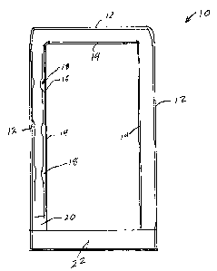
Figure 1 is a partial sectional view through a diaphragm assembly used in
connecting the ends of adjacent vehicles.
Referring to the drawings in gt~eater detail and by reference characters
thereto, the
diaphragm stricture, which is generally desiby reference numeral 10, includes
an
outer diaphragm defined by outer walls 12 and inner walls 14. The diaphragm
structure
is essentially that of a tube such as is known in the prior art and as
previously mentioned,
-2-

CA 02397859 2002-08-13
is shown in U.S. Patent 4,599,94?. At the lower end, there is provided a
bottom plate
generally designated by reference nwneral 22.
Placed intermediate of diaphragm walls 12 and 14 is an inner bladder 16. As
may
be seen, inner bladder 16 has portions generally designated by reference
numeral 18
which are not expanded outwardly at normal operating pressure. However, when
the
pressure increases due to increased temperattuc, the recessed portions 18
allow for the
increased volume of air without increasing the pressure within bladder 16.
Similarly,
when fully inflated and under cold conditions, the bladder 16 returns to the
position
shown in Figure 1 while still maintaining portions inffat~ed to contact an
outer
diaphragm 10.
In conjunction with the about, or as an alternative thereto, and as may be
sees in
Figure 1, there may be provided a space 20 at either end of bladder 16, Space
20 allows
for the longitudinal expansion of bladder 16 for the reasons mentioned above.
It will be understood that the above described embodiments are for purposes of
illustration only and that c6angeg and modifications may be made thereto
without
dep~arang from the spirit and scope of the invention.
-3-

Representative Drawing
A single figure which represents the drawing illustrating the invention.
Administrative Status

2024-08-01:As part of the Next Generation Patents (NGP) transition, the Canadian Patents Database (CPD) now contains a more detailed Event History, which replicates the Event Log of our new back-office solution.

Please note that "Inactive:" events refers to events no longer in use in our new back-office solution.

For a clearer understanding of the status of the application/patent presented on this page, the site Disclaimer , as well as the definitions for Patent , Event History , Maintenance Fee  and Payment History  should be consulted.

Event History

Description Date
Revocation of Agent Requirements Determined Compliant 2021-04-01
Inactive: IPC from MCD 2006-03-12
Application Not Reinstated by Deadline 2005-03-09
Inactive: Dead - Application incomplete 2005-03-09
Deemed Abandoned - Failure to Respond to Maintenance Fee Notice 2004-08-09
Deemed Abandoned - Failure to Respond to Notice Requiring a Translation 2004-03-09
Inactive: Cover page published 2004-02-08
Application Published (Open to Public Inspection) 2004-02-08
Inactive: Incomplete 2003-12-09
Inactive: Filing certificate - No RFE (English) 2002-12-05
Inactive: First IPC assigned 2002-10-16
Inactive: Correspondence - Formalities 2002-10-04
Inactive: Filing certificate - No RFE (English) 2002-09-24
Application Received - Regular National 2002-09-23

Abandonment History

Abandonment Date Reason Reinstatement Date
2004-08-09
2004-03-09

Fee History

Fee Type Anniversary Year Due Date Paid Date
Application fee - small 2002-08-13
Owners on Record

Note: Records showing the ownership history in alphabetical order.

Current Owners on Record
DANIEL VANDENBERGHE
Past Owners on Record
None
Past Owners that do not appear in the "Owners on Record" listing will appear in other documentation within the application.
Documents

To view selected files, please enter reCAPTCHA code :


To view images, click a link in the Document Description column (Temporarily unavailable). To download the documents, select one or more checkboxes in the first column and then click the "Download Selected in PDF format (Zip Archive)" or the "Download Selected as Single PDF" button.

List of published and non-published patent-specific documents on the CPD .

If you have any difficulty accessing content, you can call the Client Service Centre at 1-866-997-1936 or send them an e-mail at CIPO Client Service Centre.

({010=All Documents, 020=As Filed, 030=As Open to Public Inspection, 040=At Issuance, 050=Examination, 060=Incoming Correspondence, 070=Miscellaneous, 080=Outgoing Correspondence, 090=Payment})


Document
Description 
Date
(yyyy-mm-dd) 
Number of pages   Size of Image (KB) 
Claims 2004-02-07 1 2
Abstract 2004-02-07 1 2
Description 2002-08-12 3 112
Drawings 2002-08-12 1 9
Representative drawing 2003-01-13 1 5
Filing Certificate (English) 2002-09-23 1 162
Filing Certificate (English) 2002-12-04 1 159
Reminder of maintenance fee due 2004-04-12 1 109
Courtesy - Abandonment Letter (incomplete) 2004-03-29 1 167
Courtesy - Abandonment Letter (Maintenance Fee) 2004-10-03 1 178
Correspondence 2002-09-23 1 14
Correspondence 2002-10-03 3 71
Correspondence 2003-12-02 1 18