Note: Descriptions are shown in the official language in which they were submitted.
CA 02397889 2002-07-18
WO 01/54218 PCT/EPO1/00438
FUEL CELL STACK WITH COOLING FINS
AND USE OF EXPANDED GRAPHITE IN FUEL CELLS
BACKGROUND OF THE INVENTION
The invention relates to a fuel cell stack comprising: a plurality of fuel
cells electrically connected in series and having equivalent active section
areas
and circumferences, each fuel cell comprising a laminate of layers, these
comprising an electrolyte membrane and catalyst, electrode and gas diffusion
layers which functions may be combined in any combination in multifunction
layers; end and separator plates delimiting each cell; and cooling layers the
cooling function of which also may be combined with other layers in respective
multifunction layers, the cooling layers each projecting beyond the circumfe-
rential outer periphery of the laminate of the other layers thereby an inner
active area and a peripheral cooling fin area. The invention further relates
to
the use of expanded graphite for certain parts of fuel cells.
The need for a cooling system in a hydrogen-air proton exchange mem-
brane (PEM) fuel cell has been a long-standing problem. If the heat rises to a
very high temperature level, there exists the danger of drying out the mem-
brane. That results in a loss of ionic conductivity and performance, because
of the membrane's need of a high humidity level.
~5 Therefore, fuel cells which have a considerable heat dissipation need a
cooling system. For certain applications it is helpful that the cooling system
is lightweight and compact, e.g. for a mobile system. In all fuel cell
applications
the cost factor of an additional peripheral system for the fuel cell system is
to
be considered.
In U. S. Patent No. 5,595,834, a fuel cell stack is described that has a
circular cylindrical shape. For cooling, it uses separator plates that extend
CA 02397889 2002-07-18
WO 01/54218 2 PCT/EPO1/00438
radially outward from the periphery of the stack to serve the additional
function
of cooling fins. However, the heat transfer to the cooling fins and further to
an
air stream is restricted which is a considerable limitation particularly for
larger
cell areas and high temperature gradients and weights. That is because the
S cooling area of the ring-shaped cooling fins is not sufficient unless using
unduely thick layers and broad rings with the consequence of a large overall
weight and volume. Rather, the design of the prior art provides relatively
large
active section areas where waste heat is produced and only relatively small
cross sectional areas to conduct the heat outside, and relatively restricted
cooling fin areas. An additional cooling system will be necessary that
increases
the peripheral aggregates of the total system.
U. S. Patent No. 5,776,625 and WO 98/ 11616 describe similar heat
removal schemes. The bipolar plates extend in length or width over the active
area of each single cell of the fuel cell stack, forming fins at opposing
stack
edges or at one stack side, respectively. The concomitant increase in stack
surface area allows the stack to be cooled e. g. via air that is blown across
its
surface by a fan.
In the prior art, no features are disclosed that improve the ratio of the
heat dissipation ability to the heat generation in the active area while using
thin and lightweight and limitedly large heat conducting layers. A need exists
for a cooling system for fuel cell stacks that is inexpensive, lightweight,
com-
pact, and conducts all the waste heat of the reaction process out of the fuel
cell
stack.
For cooling elements, but also for other components of fuel cells, suitable
materials are to be found.
SUMMARY OF THE INVENTION
This invention relates to fuel cell stacks, particularly to those composed
of air breathing proton exchange membrane fuel cells, more particularly
polymer electrolyte membrane fuel cells, that operate with air as a reactant
and
cooling gas and have cooling layers comprising external cooling fins. The
CA 02397889 2002-07-18
WO 01/54218 3 PCT/EPO1/00438
cooling layers may be part of the single fuel cells and extend parallelly to
the
flat fuel cell extension. The purpose is to bring out the total heat of the
reaction
process, at first from the inside of the stack to the cooling fins and further
from
the cooling fins to ambient air or another cooling fluid.
The fuel cell stack of the invention is characterized in that the ratio of the
of circumference and active area of the fuel cells, defined by the geometrical
shape of the active area, extends the corresponding ratio of a square active
area; or, in other words and rather seen from the perspective of the prism
shaped stack, that the ratio of the circumference to the active section area
of
the stack, defined by the geometrical shape of the active section area,
extends
the corresponding ratio of a square base prism, i.e. of the transversal
section
of a straight parallelepiped with a square base, with the same section area.
This
provides for a relatively longer circumferencial line around each cell and
further
for a larger fin area in relation to the fin width, with the consequence of a
lower
1 S heat conduction resistance and a higher heat convection.
The geometrical form of the fuel cells, being members of the fuel cell stack
or another configuration of one or more cells itself, is preferably
rectangular,
or at least has a geometric shape that has a relatively high circumference
compared to the area. With this configuration, the distance that the total
waste
heat transport has to cover is short, and the cross-section depending on the
thickness and the extension of the cooling layer, to conduct the heat outside
is high enough even if rather thin cooling layers are used. The smaller
distance
of the rectangular fuel cell is used as a pathway for the heat. The result of
this
shape is that the cell, especially the cooling layer, has less weight than if
conventional shapes, like a circle or a square, are used. And as mentioned,
for
an equal extending width, the circumferential cooling fin has a larger area
for
dissipating the heat.
Though not necessary, it will be assumed favourable to use the separator
plates, i. e. the bipolar plates separating the single cells in the stack, for
the
cooling plates. However, there is some difficulty in the structure of the
bipolar
plate. On one hand, the bipolar plate must have enough electric conductivity
CA 02397889 2002-07-18
WO 01/54218 4 PCT/EPO1/00438
orthogonal to the plane of the fuel cell. That is one reason why most fuel
cells
use a graphite or metal plate as a bipolar plate. But in order to use the
bipolar
plate as a cooling fin, the heat (or nearby equivalently the electrical)
conductivi-
ty parallel to the plane of the fuel cell must be enlarged to bring out all
the
waste heat of the reaction processes. Therefore, in one embodiment the present
invention uses a foil containing expanded graphite that has extremely anisotro-
pic features concerning heat and electrical conductivity. The heat
conductivity
may be fifty (50) times lager parallel to the sheet plane than orthogonal to
that
plane.
The material that is used for the cooling fin may be rather lightweight.
That brings the whole system nearer to the small portable market. A preferred
material for use in the cooling layer, according to the invention, is expanded
graphite which if also used as a gas diffusion material may be mixed with
soot.
Expanded graphite is also a useful material for the electrodes of the fuel
cell,
and for the gas diffusion layer or flow field; the invention also relates to
the
choices of this material for the mentioned components.
The preferred shape of the active area of the cell is more or less rectangu-
lar. Preferably the length is about 1.5 times the width. More preferably, the
length is 2.5 to 3.5 times the width.
The cooling layer may be an extension of the anode or cathode flow field
or of the bipolar plate or may even be an extension of one electrode.
Preferably,
it covers the whole active area.
BRIEF DESCRIPTION OF THE DRAWINGS
Figure 1 is a diagrammatic representation of a fuel cell stack with cooling
fins;
Figure 2 is a diagrammatic plan view representation of a cooling fin with
gas channels;
Figure 3 is a diagrammatic representation of a heat removing system with
a cooling fin and a blower.
CA 02397889 2002-07-18
WO 01/54218 5 PCT/EPOI/00438
DETAILED DESCRIPTION OF EMBODIMENTS OF THE INVENTION
A polymer electrolyte membrane fuel cell stack 1 consists of a series of
single fuel cells 2 separated by bipolar plates 3. Each fuel cell 2 comprises
a
catalysed membrane 5 to which at both sides a combined gas diffusion and
electrode layer 7 is laminated. Between one of the layers 7 of each cell 2 and
the associated bipolar plate 3, a cooling layer 9 is inserted that conducts
all
the waste heat out of the fuel cell, and transfers this heat outside of the
cell
first to a cooling fin 11 which is a more or less broad rim of the layer 9
outside
of the proper stack, and from there to ambient air or another cooling fluid,
as
shown in Figure 1. End plates 13 form layers at the opposite ends of the fuel
cell stack 1.
The geometrical form of the fuel cells 2, being members of the fuel cell
stack 1 or of an equivalent configuration of one or more cells, is shown to be
longitudinally rectangular, but at least has a geometric shape that has a
relatively high circumference 14 compared to the cell area which is the
active,
transversal section area 15 of the stack. Another possible section shape is
e.g.
an ellipse. With such configuration, the distance that the total waste heat
has
to pass through is short, and the cross-section within the cooling layer to
conduct the heat outside is high enough even if rather thin cooling layers 9
are
used. The small distance from the place of heat generation in the active area
15 to the fin 11 in the rectangular fuel cell is used as a pathway for the
heat,
and the result of this shape is that the stack 1, and especially its cooling
layers
9, has/have less weight than if conventional shapes, like a circle or a
square,
are used. Further, for an equal width of the circumferential fin 11, the area
of
the fin 11 relatively to the active area 15 is larger.
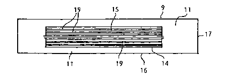
The geometrical form of the cooling layers 9 is shown in Figure 2 to also
have rectangular shape, and has a length 16 and a width 17. The length 16
of the cooling layer 9 extends the length of the active area 15 of the fuel
cells
2, as shown in Figures 1 and 3, and the width 17 of the cooling layer 9
extends
the width of the active area 15, leading to the circumferential rim-like
cooling
fin 11 extending around the cell circumference 14. Figure 2 further shows the
CA 02397889 2002-07-18
WO 01/54218 6 PCT/EPOI/00438
cooling layer 9 to have parallel channels 19 serving as ducts for reaction gas
which usually is air which could be pumped into the channels by a (non-
depicted) air pump perhaps via a filter. A blower 20 shown in Fig. 3 serves
for
cooling the cooling fins 11 around the stack 1. The blower 20 can be mounted
on an extension of the plate 13 or on some mounting legs, not shown. It
transports the cooling air through gaps 22 formed between subsequent cooling
fins 11.
Figure 1 shows the fuel cells 2 with the cooling and gas distribution
layers 9 on the cathode side. The anode or the cathode or both layers may be
designed in that way.
The material of the cooling layers 9 may have the following properties.
In order to remove the heat parallel to the cell area, a material is used that
has
high heat conductivity (?~), and low density (p) in order to save weight. A
number
that charaterizes that property of the material is the ratio ?~/ p. Several
materi-
als and their properties are given in Table I.
TABLE I
Pure Element Heat Conductivi-Density
tS' (g/ cm3) (W cm3 / m K
g)
(W/m K)
Cu 401 8.96 44.8
Ag 429 10.5 40.9
A1 237 2.7 87.8
Ti 21.9 4.5 4.9
Be 201 1.85 108.6
Graphite 150 2.0 75
Foil made of 165 (parallel) 1.1 150
expanded gra- 3 (orthogonal)
phite (i.e.,
Sigra-
flex from SGL
Carbon AG)
Mg 156 1.74 89.6
CA 02397889 2002-07-18
WO 01/54218 ~ PCT/EPO1/00438
Ca 125 1.55 80.6
Li 84.8 0.534 158.8
Alkali metals, especially Lithium, have a very desirable ?~/ p ratio, but
because of their chemical reactivity and poor mechanical properties they are
not desirable as construction materials. Beryllium has very good properties
too,
but it is rather toxic. Al, Mg and, preferred for the purpose, expanded
graphite
are some of the remaining materials. Al is a commonly available material. It
is important that the Al is pure because A1 alloys have a much lower thermal
conductivity. However, A1 is chemically unstable at fuel cell conditions. A
conductive coating may be used, as described in Example 3, to overcome that
instability.
The material that has the most benefits is a foil that contains expanded
graphite. In order to enhance the mechanical stability and the gas tightness
(if needed) of this material, it may be impregnated with conventional resins
(epoxy, phenol, phenolic, or furan resin). The electric conductivity of the
material is, despite of its anisotropicity, high enough to conduct the
electric
current of the cells. Another layer material that fits very well to the
require-
ments of the cooling layers 9 if at the same time serving as the bipolar
plates
3 is a composite material which consists of a metal core, e.g. of Al, Cu, Mg,
that
is plated with a carbon-polymer layer.
With the extended cooling fins described, it is possible to bring out all
the waste heat of the reaction processes. Except for the blower 20, no addi-
tional cooling aggregates are necessary. In the special case of a very small
fuel
cell area, even the blower may be left off. This helps to reduce the
peripheral
aggregates of the whole system and saves costs.
EXAMPLE 1:
In the special form described above the cooling layer 9 also has the
function of a gas distribution layer (flow field). In the example, a foil with
expanded graphite is used (e. g., Sigraflex from SGL Carbon AG), which is of
CA 02397889 2002-07-18
WO 01/54218 g PCT/EPO1/00438
a material having an extremely high heat conductivity (see Table I) in the
parallel direction and wherein it is easily possible to press or manufacture
in
another way the gas-channels 19, because the material is soft and deformable
due to low content or absence of polymeric binders.
The pressing process has two results. One is that the foil is compressed
for forming the channels. This means that the density of the material in the
channels is higher. For this special material the heat conductivity parallel
to
the plane of the fuel cell increases with the density of the material. The
chan
nels 19 within the cooling layer 9 therefore do not have a negative but rather
a slightly positive effect on the heat conductivity.
The second result is that all channel structures also have parts, i.e. hills,
that are higher than the channels. These parts have the function of conducting
the electricity orthogonally to the plane of the cells 2 because of the series
connection in the fuel cell stack 1. The electric conductivity decreases in
the
direction orthogonally to the plane of the cells 2 with the density of the
materi-
al, but high conductivity is needed at those parts only where the material is
not compressed. So the effect on the paths for the electric conductivity is
not
a negative one due to such manufacturing process of the channels 19. In
summary, in consequence of the channel structure 19, the heat conductivity
is increased, while the electrical conductivity is constant.
The same arrangement however is possible with other materials (besides
expanded graphite) that have a good ratio of density and heat conductivity and
that meet the requirements of chemical stability in the fuel cell.
EXAMPLE 2:
In this embodiment of the present invention the cooling layers 9 fulfil the
requirements of the bipolar plates 3 being gas separators, too, and thus must
be gas-tight. This embodiment may be with or without a channel structure as
described above.
To overcome the problem with conventional bipolar plate materials that
are not useful to bring out all the waste heat parallel to the plane of the
cell
CA 02397889 2002-07-18
WO 01/54218 9 PCT/EPO1/00438
because of no enhanced heat conductivity in this direction, the same advanced
material as in Example 1 is useful. To fulfil the requirement of gas-
tightness,
the foil with expanded graphite has to be impregnated or extremely com
pressed. As an impregnation material a polymer could be used, preferred an
epoxy, furan or phenol resin.
In this example, the fuel cells 2 in the stack 1 with the bipolar separator
plates 3 also serving as the cooling layers 9 have the following geometrical
data:
Active area of each cell: 39 mm ~ 120 mm
Extension of the cooling fin 1
outside of the circumference 14
and of the active area 15: 20 mm
Thickness of the expanded
graphite foil: 0.6 mm (i. e., Sigraflex
from SGL)
Density of the foil
(achieved by compression) 1.3 g/ cm3
Power density: 0.3 W/cm2
The stack 1 has thirty-six (36) of these cells 2 and has a power output
of about 500 W. If rather deep channels 19 are required, the thickness of the
layer 9 may be enhanced in the active area. The thickness and the mass of the
cooling layers 9 still are even smaller than that of liquid cooled systems and
all the peripheral aggregates with respect to liquid cooling are eliminated.
The
cooling layers and the bipolar plates being combined to a multipurpose-layer,
the structure of a metal core and a coating layer, e.g. a carbon-polymer
layer,
serves for a good gas-tightness.
EXAMPLE 3:
In another embodiment, the cooling layer 9 again has a double function.
In addition to working as a cooling fin, the cooling layer 9 also acts as the
electrode. The combined electrode and cooling layer may have the pressed gas
CA 02397889 2002-07-18
WO 01/54218 1 O PCT/EPOI/00438
channels 19 as described, and preferably the layer is also gas permeable.
As a preferred material a foil made of expanded graphite is used. The
permeability may be reached by using expanded graphite that has a low
density, which means that during manufacturing of the foil a low compression
force was applied. This gas permeability is only necessary within the active
area
of the fuel cell 2. To prevent gas losses due to the gas permeability parallel
to the foil layer, the material in the cooling fin part 11 may be compressed.
Another way to reach a gas impermeability at the cooling fin part 11 (or at
least
at the transition, i.e. the circumference 14, between active area 15 and
cooling
10 fin 11) is to impregnate that part with a polymer, preferably an epoxy,
furan
or phenol resin.
To reach higher gas permeability in the active area of the foil, in the step
before the manufacturing of the foil from the carbon powder mixture the
expanded graphite powder may be mixed with a high pore volume soot. The
15 mixing rate may be 90 parts of expanded graphite or less and 10 parts of
soot
or more, preferred is a ratio of 60 : 40.
To improve the contact between the electrode/cooling layer and the
membrane 5, a micro-porous layer may be fitted on the side of the electrode
adjacent to the membrane. In Figure 1, the place of such micro-porous layer
is shown at 27. Such a micro-porous layer may be made of soot and a hydro-
phobic material, i. e., polytetrafluoroethylene (PTFE). The connection between
the electrode/cooling layer and the micro-porous layer may be obtained by any
known coating method, preferably by spraying a suspension onto the surface
of the electrode/cooling layer.
EXAMPLE 4:
In another embodiment, one or more of the blowers 20 are added to the
fuel cell stack 1. They fulfill the task of removing the heat from the cooling
fins
11, passing through the gaps 22 formed between subsequent cooling fins 11.
The geometrical arrangement of the blowers 20 is important.
Due to the rectangular sectional shape of the fuel cell stack 1, the
CA 02397889 2002-07-18
WO 01/54218 11 PCT/EPO1/00438
pathway for the cooling air 25 parallel to the length is rather long. This
results
in a relatively high pressure drop within the cooling air path, thereby
requiring
a high power. To overcome this problem, the flow of the cooling air 25 is
divided
in at least two directions of pathways 28 and 29 for each long side 16 of the
rectangular section, these pathway flows cooling different parts of the
cooling
fins 11. The flow amount and the flow rate are reduced within each gap 22
formed by the subsequent cooling fins. Therefore the pressure drop is reduced
quadratically as a function of the number of pathways 28 and 29. Figure 3
shows such embodiment of the heat removing system, using the cooling fins
11 together with the blower 20 which may be arranged at the width sides 17
of the rectangle as well.
In another embodiment of Example 4, the blower 20 is replaced by the
air stream generated due to the running of a vehicle.
Also in another embodiment of the present invention, the blower may be
1 S dispensed with. In this embodiment, the cooling air flow results only
because
of convection. This is possible for rather small stacks or for stacks with low
power output per unit active area only.