Language selection

Search

Patent 2397954 Summary

Third-party information liability

Some of the information on this Web page has been provided by external sources. The Government of Canada is not responsible for the accuracy, reliability or currency of the information supplied by external sources. Users wishing to rely upon this information should consult directly with the source of the information. Content provided by external sources is not subject to official languages, privacy and accessibility requirements.

Claims and Abstract availability

Any discrepancies in the text and image of the Claims and Abstract are due to differing posting times. Text of the Claims and Abstract are posted:

  • At the time the application is open to public inspection;
  • At the time of issue of the patent (grant).
(12) Patent Application: (11) CA 2397954
(54) English Title: METHOD OF ISOLATING DATA IN A POWER LINE COMMUNICATION NETWORK
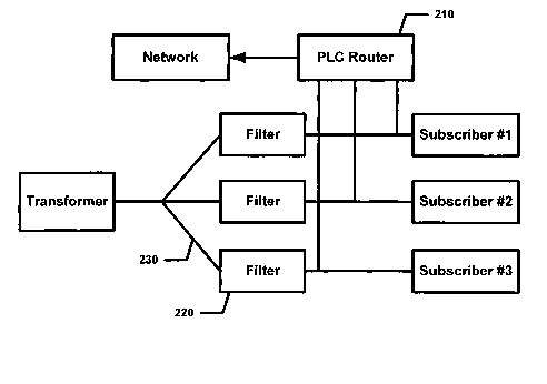
(54) French Title: PROCEDE D'ISOLATION DE DONNEES DANS UN RESEAU DE COMMUNICATIONS A LIGNE ELECTRIQUE
Status: Deemed Abandoned and Beyond the Period of Reinstatement - Pending Response to Notice of Disregarded Communication
Bibliographic Data
(51) International Patent Classification (IPC):
  • H04B 3/54 (2006.01)
(72) Inventors :
  • KLINE, PAUL (United States of America)
(73) Owners :
  • CURRENT TECHNOLOGIES, LLC
(71) Applicants :
  • CURRENT TECHNOLOGIES, LLC (United States of America)
(74) Agent: SMART & BIGGAR LP
(74) Associate agent:
(45) Issued:
(86) PCT Filing Date: 2001-01-19
(87) Open to Public Inspection: 2001-07-26
Availability of licence: N/A
Dedicated to the Public: N/A
(25) Language of filing: English

Patent Cooperation Treaty (PCT): Yes
(86) PCT Filing Number: PCT/US2001/001810
(87) International Publication Number: WO 2001054297
(85) National Entry: 2002-07-22

(30) Application Priority Data:
Application No. Country/Territory Date
60/177,237 (United States of America) 2000-01-20

Abstracts

English Abstract


Isolating data in a power line communications system. Although plural
subscribers receive electric power distributed from a common distribution
transformer, it is desirable to isolate their branch lines from one another
when those branch lines are used to conduct data communications as a
supplement to electric power delivery. This isolation of branch lines is
implemented in a centralized way at the distribution transformer, or
alternatively, in a distributed way at each subscriber's premises. These
implementations are made using low pass filters (which pass the power but
block the data) and power line communications routers or power line
communications repeaters.


French Abstract

L'invention concerne l'isolation de données dans un système de communications à ligne électrique. Bien que l'alimentation électrique de plusieurs abonnés puisse être distribuée à partir d'un transformateur de distribution commun, il est souhaitable d'isoler leurs lignes de dérivation les unes des autres lorsqu'on les utilise pour communiquer des données en plus de distribuer de l'électricité. L'isolation des lignes de dérivation est mise en place de manière centralisée au niveau du transformateur de distribution, ou de manière distribuée au niveau de chaque local d'abonné. Ces mises en oeuvre sont effectuées à l'aide de filtres passe-bas (qui laissent passer l'électricité mais bloquent les données) et de routeurs de communication à ligne électrique ou de répéteurs de communication à ligne électrique.

Claims

Note: Claims are shown in the official language in which they were submitted.

WHAT IS CLAIMED IS:
1. A system for providing network communications isolation in a branch line
connecting a subscriber device at a subscriber premises to a network, the
system
comprising:
an electric power distribution transformer;
a branch line connected between the transformer and the subscriber's premises;
a low pass filter connected in the branch line at a location adjacent the
transformer;
a power line communications router connected to the network and coupled to the
branch line at a location adjacent the filter, on the subscriber side of the
filter;
wherein, when the subscriber device is coupled to the branch line, the
subscriber
device is coupled to the network and is isolated from the transformer by the
filter.
2. A network coupler to provide network communications isolation in a branch
line connected to a subscriber premises through an electric power meter, the
network
coupler comprising:
a low pass filter coupled to the branch line adjacent to the power meter; and
power line communications repeater connected to the branch line across the low
pass filter.
3. The network coupler of claim 2, wherein the low pass filter is disposed on
the
subscriber side of the power meter.
4. The network coupler of claim 3, wherein the power line communications
repeater is connected across both the low pass filter and the power meter.
5. The network coupler of claim 2, wherein the low pass filter is disposed on
the
transformer side of the power meter.
6. The network coupler of claim 5, wherein the power line communications
repeater is connected across both the low pass filter and the power meter.
-6-

7. A network coupler to provide network communications isolation in a branch
line connected to a subscriber premises through an electric power meter, the
network
coupler comprising:
a low pass filter coupled to the branch line adjacent to the power meter; and
power line communications repeater connected to the branch line across both
the
low pass filter and the power meter.
8. A network isolator to provide network communications isolation in a branch
line connected to a subscriber premises through an electric power meter, the
isolation
being provided between a network located at the subscriber premises a
transformer
connected to the branch line, the network isolator comprising:
a low pass filter coupled to the branch line adjacent to the power meter,
wherein
the low pass filter is disposed on the subscriber side of the power meter.
9. A network isolator to provide network communications isolation in a branch
line connected to a subscriber premises through an electric power meter, the
isolation
being provided between a network located at the subscriber premises a
transformer
connected to the branch line, the network isolator comprising:
a low pass filter coupled to the branch line adjacent to the power meter,
wherein
the low pass filter is disposed on the transformer side of the power meter.
-7-

Description

Note: Descriptions are shown in the official language in which they were submitted.


CA 02397954 2002-07-22
WO 01/54297 PCT/USO1/01810
METHOD OF ISOLATING DATA IN A POWER LINE COMMUNICATION NETWORK
INTRODUCTION
1. The present invention relates generally to the field of electrical
communications
via power lines. More particularly, the present invention relates to isolating
data in a
power line communications system.
BACKGROUND OF THE INVENTION
2. A typical electric distribution configuration has a transformer which steps
medium
voltage down to a few hundred volts AC (typically between 100 and 240 VAC).
The Low
Voltage (LV) is fed to several homes.
3. Referring to Fig. 1, the typical electric power distribution architecture
is illustrated.
No filter or other barrier is employed to isolate data from one residence to
the next. Using
this architecture for a power line communications system, typically a power
line signal
containing the data will be fed at the transformer. There are four potential
problems with
this topology for communications.
4. First, the bandwidth is shared between plural subscribers. Second, noise
from
another subscriber using a different type of power line communication system
or noise
from another subscriber's appliances may cause interference. Third,
subscribers using the
same system can interact with each other. Fourth, since one subscriber
receives the other
subscriber's data, there is a lack of security.
5. Thus, what is needed is a way of isolating data from subscriber to
subscriber to
alleviate the problems discussed above.
SUMMARY OF THE INVENTION
6. It is an object of the present invention to enable isolation of data from
subscriber to
subscriber.
7. It is another object of the present invention to enable isolation of data
from a
subscriber to the distribution transformer.

CA 02397954 2002-07-22
WO 01/54297 PCT/US01/01810
8. Isolation structures to realize these objects are implemented in a
centralized way at
the distribution transformer, or alternatively, in a distributed way at each
subscriber's
premises. These implementations are made using low pass filters (which pass
the power
but block the data) and power line communications routers or power line
communications
repeaters.
BRIEF DESCRIPTION OF THE DRAWING
9. Additional objects and advantages of the present invention will be apparent
in the
following detailed description read in conjunction with the accompanying
drawing figures.
10. Fig. 1 illustrates a conceptual view of a typical electric distribution
topology.
11. Fig. 2 illustrates a block diagram view of centralized data isolation.
12. Fig. 3 illustrates a block diagram view of an embodiment of the present
invention
having isolation before the power meter.
13. Fig. 4 illustrates a block diagram view of an embodiment of the present
invention
having isolation after the power meter.
14. Fig. 5 illustrates a block diagram view of an embodiment of the present
invention
having isolation bridging the power meter.
15. Fig. 6 illustrates a block diagram view of an embodiment of the present
invention
having a LAN only topology with a filter before the meter.
16. Fig. 7 illustrates a block diagram view of an embodiment of the present
invention
having a LAN only topology with a filter after the meter
DETAILED DESCRIPTION OF THE INVENTION
17. According to alternate embodiments, data isolation is accomplished in a
centralized manner, in a distributed manner (i.e., at the subscriber), or in a
hybrid manner
that is a combination of centralized and distributed.
18. According to one aspect of the invention, a system provides for network
communications isolation in a branch line connecting a subscriber device at a
subscriber
premises to a network. The system includes an electric power distribution
transformer, a
branch line (connected between the transformer and the subscriber's premises),
a low pass
-2-

CA 02397954 2002-07-22
WO 01/54297 PCT/USO1/01810
filter, and a power line communications muter. The low pass filter connected
in the
branch line at a location adjacent the transformer. The power line
communications muter
is connected to the network and coupled to the branch line at a location
adjacent the filter,
on the subscriber side of the filter. When the subscriber device is coupled to
the branch
line, the subscriber device is coupled to the network and is isolated from the
transformer
by the filter.
19. According to another aspect of the invention a network coupler. The
network
coupler provides network communications isolation in a branch line connected
to a
subscriber premises through an electric power meter. The network coupler
includes a low
pass filter and a power line communications repeater. The low pass filter is
coupled to the
branch line adjacent to the power meter. The power line communications
repeater is
connected to the branch line across the low pass filter.
20. On the one hand, the power line communications repeater is connected
across both
the low pass filter and the power meter. In the alternative, the power line
communications
repeater is connected across only the low pass filter. The low pass filter is
disposed either
on the subscriber side of the power meter, or on the transformer side of the
power meter.
21. According to yet another aspect of the present invention, a network
isolator
provides network communications isolation in a branch line connected to a
subscriber
premises through an electric power meter. The isolation is provided between a
network
located at the subscriber premises a transformer connected to the branch line.
The
network isolator includes a low pass filter. The low pass filter is coupled to
the branch
line adjacent to the power meter. The low pass filter is disposed either on
the subscriber
side of the power meter, or on the transformer side of the power meter.
22. Referring to Fig. 2, a centralized power line communications (PLC) router
210 is
illustrated. The centralized PLC router 210 is connected separately to each
branch line,
which in turn connects to the subscriber. A filter 220 passes the high power
electricity
(100 VAC to 240 VAC) but blocks the power line communications signal. This
filter 220
is implemented using electronic components such as inductors, capacitors and
resistors.
This method requires splicing the electric power line and inserting the filter
210 in series
with the line 230.

CA 02397954 2002-07-22
WO 01/54297 PCT/USO1/01810
23. A less expensive way of implementing this filter, which does not require
cutting
the power line, uses a ferrite toroid as a common-mode choke. This is done by
simply
feeding an electric power line through a toroid, thus allowing the electric
power (50-60Hz)
to pass yet blocking the higher frequency signals that contain the power line
communications data. In most situations the toroid method is preferred.
24. In conjunction with the centralized method, or as an alternative, data is
isolated
using a distributed approach. In this approach a filter (such as described
above) is placed
at the subscriber's location. A power line data repeater, which regenerates
the data, is
connected in parallel with the filtering device. This topology addresses the
noise,
interference and security issues. However, the bandwidth is shared between
each
subscriber connected to the transformer.
25. Referring to Fig. 3 a block diagram view of an embodiment of the present
invention having isolation before the power meter 300 is illustrated. This is
an
implementation according to a distributed topology. A PLC repeater 310 and a
filter 320
are connected in parallel with one another and in series with the power meter
300. The
power meter 300 is disposed between the subscriber's house 340 and the PLC
repeater
310.
26. Referring to Fig. 4 a block diagram view of an embodiment of the present
invention having isolation after the power meter 400 is illustrated. This is
another
implementation according to a distributed topology. A PLC repeater 410 and a
filter 420
are connected in parallel with one another and in series with the power meter
400. The
PLC repeater 410 is disposed between the subscriber's house 440 and the power
meter
400.
27. Functionally, the differences between the distributed topology
implementations
illustrated in Figs. 3 & 4 are insubstantial. However, depending on the
deployment one
may be easier to implement than the other.
28. Referring to Fig. 5, a block diagram view of an embodiment of the present
invention having isolation bridging the power meter is illustrated. A filter
520 is
connected in series with the power meter 500, and that series combination is
connected in
parallel with a PLC repeater 510.
-4-

CA 02397954 2002-07-22
WO 01/54297 PCTNSO1/01810
29. Although the distributed topology of this embodiment is potentially
difficult to
deploy, it has certain performance advantages. Performance according to this
embodiment
is superior since the electric meter 500 presents some attenuation of the
power line
communication signals. Thus, in this topology the PLC repeater 510 repeats
signals across
the filter 520 and electric meter 500. This achieves a better signal-to-noise
ratio by
avoiding the attenuation that would otherwise be introduced by the electric
meter 500.
30. Referring to Figs. 6 & 7, a filtering device is placed on the power line
adjacent the
subscriber's premises. This is useful in cases where an internal Local Area
Network
(LAN) exists within the premises and access to a Wide Area Network (WAN) in
not
required. This provides security for the LAN as well as reduces interference
from the
outside. It also isolates the LAN from the WAN in case a WAN is deployed.
According
to the embodiment illustrated in Fig. 6, the filter 610 and the electric meter
620 are
connected in a serial with one another, with the filter 610 before the
electric meter 620.
Alternatively, Fig. 7 illustrates the filter 710 and the electric meter 720 as
being connected
in a serial with one another, with the filter 710 placed after the electric
meter 720. The
arrangement according to both of these illustrated topologies functionally
perform the
same. However, depending on the deployment one may be easier to implement than
the
other.
31. The present invention has been described in terms of preferred
embodiments,
however, it will be appreciated that various modifications and improvements
may be made
to the described embodiments without departing from the scope of the
invention.
-5-

Representative Drawing
A single figure which represents the drawing illustrating the invention.
Administrative Status

2024-08-01:As part of the Next Generation Patents (NGP) transition, the Canadian Patents Database (CPD) now contains a more detailed Event History, which replicates the Event Log of our new back-office solution.

Please note that "Inactive:" events refers to events no longer in use in our new back-office solution.

For a clearer understanding of the status of the application/patent presented on this page, the site Disclaimer , as well as the definitions for Patent , Event History , Maintenance Fee  and Payment History  should be consulted.

Event History

Description Date
Letter Sent 2009-04-16
Inactive: Correspondence - Transfer 2008-11-28
Inactive: Office letter 2008-10-14
Letter Sent 2008-06-26
Time Limit for Reversal Expired 2007-01-19
Application Not Reinstated by Deadline 2007-01-19
Inactive: Abandon-RFE+Late fee unpaid-Correspondence sent 2006-01-19
Deemed Abandoned - Failure to Respond to Maintenance Fee Notice 2006-01-19
Letter Sent 2002-12-10
Inactive: Cover page published 2002-12-09
Inactive: Notice - National entry - No RFE 2002-12-05
Correct Applicant Requirements Determined Compliant 2002-12-05
Application Received - PCT 2002-09-23
Inactive: Single transfer 2002-09-20
Amendment Received - Voluntary Amendment 2002-09-20
Amendment Received - Voluntary Amendment 2002-07-23
National Entry Requirements Determined Compliant 2002-07-22
Application Published (Open to Public Inspection) 2001-07-26

Abandonment History

Abandonment Date Reason Reinstatement Date
2006-01-19

Maintenance Fee

The last payment was received on 2005-01-10

Note : If the full payment has not been received on or before the date indicated, a further fee may be required which may be one of the following

  • the reinstatement fee;
  • the late payment fee; or
  • additional fee to reverse deemed expiry.

Please refer to the CIPO Patent Fees web page to see all current fee amounts.

Fee History

Fee Type Anniversary Year Due Date Paid Date
Basic national fee - standard 2002-07-22
MF (application, 2nd anniv.) - standard 02 2003-01-20 2002-07-22
Registration of a document 2002-09-20
MF (application, 3rd anniv.) - standard 03 2004-01-19 2003-12-30
MF (application, 4th anniv.) - standard 04 2005-01-19 2005-01-10
Registration of a document 2008-03-31
Owners on Record

Note: Records showing the ownership history in alphabetical order.

Current Owners on Record
CURRENT TECHNOLOGIES, LLC
Past Owners on Record
PAUL KLINE
Past Owners that do not appear in the "Owners on Record" listing will appear in other documentation within the application.
Documents

To view selected files, please enter reCAPTCHA code :


To view images, click a link in the Document Description column. To download the documents, select one or more checkboxes in the first column and then click the "Download Selected in PDF format (Zip Archive)" or the "Download Selected as Single PDF" button.

List of published and non-published patent-specific documents on the CPD .

If you have any difficulty accessing content, you can call the Client Service Centre at 1-866-997-1936 or send them an e-mail at CIPO Client Service Centre.


Document
Description 
Date
(yyyy-mm-dd) 
Number of pages   Size of Image (KB) 
Representative drawing 2002-07-22 1 6
Cover Page 2002-12-09 1 37
Description 2002-07-22 5 225
Claims 2002-07-22 2 66
Abstract 2002-07-22 1 54
Drawings 2002-07-22 4 29
Notice of National Entry 2002-12-05 1 189
Courtesy - Certificate of registration (related document(s)) 2002-12-10 1 106
Reminder - Request for Examination 2005-09-20 1 116
Courtesy - Abandonment Letter (Maintenance Fee) 2006-03-16 1 174
Courtesy - Abandonment Letter (Request for Examination) 2006-03-30 1 166
PCT 2002-07-22 5 195
PCT 2002-07-23 7 275
Correspondence 2008-10-14 1 20
Correspondence 2009-04-16 1 17