Language selection

Search

Patent 2398218 Summary

Third-party information liability

Some of the information on this Web page has been provided by external sources. The Government of Canada is not responsible for the accuracy, reliability or currency of the information supplied by external sources. Users wishing to rely upon this information should consult directly with the source of the information. Content provided by external sources is not subject to official languages, privacy and accessibility requirements.

Claims and Abstract availability

Any discrepancies in the text and image of the Claims and Abstract are due to differing posting times. Text of the Claims and Abstract are posted:

  • At the time the application is open to public inspection;
  • At the time of issue of the patent (grant).
(12) Patent: (11) CA 2398218
(54) English Title: EMERGENCY VISION APPARATUS
(54) French Title: APPAREIL DE VISION A UTILISER EN CAS D'URGENCE
Status: Term Expired - Post Grant Beyond Limit
Bibliographic Data
(51) International Patent Classification (IPC):
  • B64D 11/00 (2006.01)
  • B64C 1/14 (2006.01)
  • B64D 13/00 (2006.01)
  • B64D 25/00 (2006.01)
  • G02B 5/00 (2006.01)
  • G02B 27/00 (2006.01)
(72) Inventors :
  • WERJEFELT, BERTIL R. L. (United States of America)
(73) Owners :
  • BERTIL R. L. WERJEFELT
(71) Applicants :
  • BERTIL R. L. WERJEFELT (United States of America)
(74) Agent: SMART & BIGGAR LP
(74) Associate agent:
(45) Issued: 2005-12-20
(86) PCT Filing Date: 2001-01-29
(87) Open to Public Inspection: 2001-08-02
Examination requested: 2002-07-24
Availability of licence: N/A
Dedicated to the Public: N/A
(25) Language of filing: English

Patent Cooperation Treaty (PCT): Yes
(86) PCT Filing Number: PCT/US2001/000659
(87) International Publication Number: WO 2001054976
(85) National Entry: 2002-07-24

(30) Application Priority Data:
Application No. Country/Territory Date
09/769,754 (United States of America) 2001-01-26
60/178,312 (United States of America) 2000-01-27

Abstracts

English Abstract


An emergency
supplementary vision device (R)
comprises a collapsible tube (2) made
of airtight material and having an
expanded form and a compact stowed
form; first and second clear member
(4)s disposed at respective first and
second ends of the tube to enable the
user to see through the tube and observe
a source of information at the other end
while smoke or other particulate matter
is in the environment: and a filter (8)
operably associated with the tube (2)
to filter the ambient atmosphere and
fill the interior of said tube with clear
air when the tube (2) is expanded to its
expanded form.


French Abstract

L'invention concerne un dispositif (R) de vision supplémentaire à utiliser en cas d'urgence. Ce dispositif comprend un tube (2) démontable fabriqué dans un matériau étanche à l'air et présentant une forme étendue et une forme compacte repliée; un premier et un second élément (4) transparents placés respectivement aux première et seconde extrémités du tube permettant à l'utilisateur de voir à travers le tube et d'observer une source d'informations se trouvant à l'autre bout alors que de la fumée et d'autres matières particulaires se trouvent dans le milieu; et un filtre (8) associé de manière fonctionnelle au tube (2), destiné à filtrer l'atmosphère ambiante et à remplir l'intérieur du tube (2) d'air pur quand le tube est dans sa forme étendue.

Claims

Note: Claims are shown in the official language in which they were submitted.

CLAIMS:
1. An emergency supplementary vision device, comprising:
a) a collapsible tube made of airtight material and having
an expanded form and a compact stowed form;
b) first and second clear members disposed at respective
first and second ends of said tube to enable a user to see
through said tube from one of said first and second ends and
observe a source of information at the other of said first and
second ends while smoke or other particulate matter is in an
environment;
c) a filter operably associated with said tube to filter
the ambient atmosphere and fill the interior of said tube with
clear air when said tube is expanded to its expanded form; and
d) a flexible support operably secured to the tube,
extending from one end of said tube to the other end, adapted
to expand said tube to its expanded form and thereby to draw
ambient air through said filter into said tube, and said
flexible support being adapted to be collapsible when said tube
is collapsed to its compact stowed form.
2. An emergency supplementary vision device as in claim 1,
wherein said flexible support is biased to expand said tube to
its expanded form.
3. An emergency supplementary vision device as in claim 1,
and further comprising:
a) a one-way valve operably disposed in series with said
filter; and
b) said valve is normally open in one direction to allow
air into said tube and normally closed in an opposite direction
to maintain the air inside said tube.
4. An emergency supplementary vision device as in claim 1,
and further comprising a closable port operably associated with
-8-

said tube to allow air within said tube to be exhausted out
when said tube is compacted down to said stowage form.
5. An emergency supplementary vision device as in claim 1,
and further comprising:
a) a source of light to aid the user to see the source of
information; and
b) a switch to control said source of light.
6. An emergency supplementary vision device as in claim 5,
wherein said switch is disposed at one end of said tube.
7. An emergency supplementary vision device as in claim 5,
and further comprising:
a) a pouch for storing said tube in the compact stowed
form; and
b) means for automatically activating said switch when
said tube is pulled out of said pouch.
8. An emergency supplementary vision device as in claim 5,
and further comprising:
a) a pouch for storing said tube in the compact stowed
form; and
b) first and second switches disposed in series with said
light source;
c) said first switch is in off state when inside said
pouch and in an on state when outside said pouch; and
d) said second switch is in an on state inside or outside
said pouch.
9. An emergency supplementary vision device as in claim 2,
wherein said flexible support includes a spring.
10. An emergency supplementary vision device as in claim 2,
wherein said flexible support is a helical spring.
-9-

11. An emergency supplementary vision device as in claim 9,
wherein said spring is disposed within said tube.
12. An emergency supplementary vision device as in claim 1,
wherein said tube is cylindrical.
13. An emergency supplementary vision device as in claim 1,
wherein said tube is an airtight fabric.
14. An emergency supplementary vision device as in claim 1,
wherein said clear members are plastic.
15. An emergency supplementary vision device as in claim 1,
wherein said filter is disposed at one end of said tube.
16. An emergency supplementary vision device as in claim 1,
wherein said filter is integrated with said tube.
17. An emergency supplementary vision device as in claim 16,
wherein a portion of said tube is made of filter material.
18. An emergency supplementary vision device as in claim 1
wherein said filter is a HEPA filter.
19. An emergency supplementary vision device, comprising;
a) a collapsible tube made of airtight material having an
expanded form and a compact stowed form, said tube being
adapted to draw in ambient air when it is manually expanded;
b) first and second clear members disposed at respective
first and second ends of said tube to enable a user to see
through said tube from one of said first and second ends and
observe a source of information at the other of said first and
second ends while smoke or other particulate matter is in an
environment;
-10-

c) a filter operably associated with said tube to filter
the ambient air drawn into said tube when said tube is
expanded; and
d) a one-way valve operably disposed in series with said
filter, said valve is normally open in one direction to allow
air into said tube and normally closed in an opposite direction
to maintain the air inside said tube.
20. An emergency supplementary vision device as in claim 19,
and further comprising a closable port operably associated with
said tube to allow air within said tube to be exhausted out
when said tube is compacted down to said stowage form.
21. An emergency supplementary vision device as in claim 19,
wherein said valve includes a flap disposed across said filter
within said tube.
22. An emergency supplementary vision device as in claim 19,
wherein said filter is a HEPA filter
23. An emergency supplementary vision device as in claim 19,
wherein said tube is an airtight fabric.
24. An emergency supplementary vision device as in claim 19,
wherein said clear members are plastic.
25. An emergency supplementary vision device as in claim 19,
wherein said filter is disposed at one end of said tube.
26. An emergency supplementary vision device as in claim 19,
wherein said filter is integrated with said tube.
27. An emergency supplementary vision device as in claim 19,
wherein said tube is made of filter material.
-11-

28. An emergency supplementary vision device as in claim 19,
wherein said filter is a HEPA filter.
29. An emergency supplementary vision device, comprising:
a) a collapsible tube made of an airtight material and
having an expanded form and a compact stowed form, said tube
including a portion made of filter material to filter the
ambient atmosphere and fill the interior of said tube with
clear air when said tube is expanded to its expanded form;
b) a flexible support operably secured to said tube,
biased to expand said tube to its expanded form and adapted to
be collapsible when said tube is collapsed to its compact
stowed form; and
c) first and second clear members disposed at respective
first and second ends of said tube to enable a user to see
throuqh said tube from one of said first and second ends and
observe a source of information at the other of said first and
second ends while smoke or other particulate matter is in an
environment.
30. An emergency supplementary vision device, comprising:
a) a collapsible tube made of airtight material and having
an expanded form and a compact stowed form;
b) first and second clear members disposed at respective
first and second ends of said tube to enable a user to see
through said tube from one of said first and second ends and
observe a source of information at the other of said first and
second ends while smoke or other particulate matter is an
environment;
c) a filter operably associated with said tube to filter
the ambient atmosphere and fill the interior of said tube with
clear air when said tube is expanded to its expanded form;
d) a source of light to aid the user to see the source of
information;
e) a switch to control said source of light;
-12-

f) a pouch for storing said tube in the compact stowed
form; and
g) means for automatically activating said switch when
said tube is pulled out of said pouch.
31. An emergency supplementary vision device, comprising:
a) a collapsible tube made of airtight material and having
an expanded form and a compact stowed form;
b) first and second clear members disposed at respective
first and second ends of said tube to enable a user to see
through said tube from one of said first and second ends and
observe a source of information at the other of said first and
second ends while smoke or other particulate matter is in an
environment;
c) a filter operably associated with said tube to filter
the ambient atmosphere and fill the interior of said tube with
clear air when said tube is expanded to its expanded form;
d) a source of light to aid the user to see the source of
information;
e) a switch to control said source of light;
f) a pouch for storing said tube in the compact stowed
form;
g) first and second switches disposed in series with said
light source;
h) said first switch is in off state when inside said
pouch and in an on state when outside said pouch; and
i) said second switch is in an on state inside or outside
said pouch.
32. An emergency supplementary vision device, comprising:
a) a collapsible tube made of airtight material and having
an expanded form and a compact stowed form;
b) first and second clear members disposed at respective
first and second ends of said tube to enable a user to see
through said tube from one of said first and second ends and
observe a source of information at the other of said first and
-13-

second ends while smoke or other particulate matter is in an
environment; and
c) a portion of said tube being made of filter material to
filter the ambient atmosphere and fill the interior of said
tube with clear air when said tube is expanded to its expanded
form.
33. An emergency supplementary vision device, comprising:
a) a collapsible tube made of airtight material having an
expanded form and a compact stowed form, said tube being
adapted to be manually expanded or compacted;
b) first and second clear members disposed at respective
first and second ends of said tube to enable a user to see
through said tube from one of said first and second ends and
observe a source of information at the other of said first and
second ends while smoke or other particulate matter is in an
environment;
c) a filter operably associated with said tube to filter
the ambient atmosphere and fill the interior of said tube with
clear air when said tube is expanded to its expanded form;
d) a one-way valve operably disposed in series with said
filter, said valve is normally open in one direction to allow
air into said tube and normally closed in an opposite direction
to maintain the air inside said tube; and
e) said valve including a flap disposed across said filter
within said tube.
-14-

Description

Note: Descriptions are shown in the official language in which they were submitted.


CA 02398218 2005-03-O1
EMERGENCY VISION APPARATUS
FIELD OF THE INVENTION
The present invention relates generally to an apparatus to
enable an operator to maintain visual contact with instruments
or other visual sources of data after smoke and/or particulate
from a fire or other sources has invaded the operator's
environment. In particular, the present relates to an
automatically expandable enclosure that bridges the gap between
the pilot and the windshield and/or instrument panel along the
pilot's line of sight and provide a clear viewing path to the
windshield and/or the instrument panel, thereby providing him
with vital information for guiding the aircraft to a safe
landing after smoke and/or particulate matter invades the
cockpit area.
-1-

CA 02398218 2005-03-O1
BACKGROUND OF THE INVENTION
Emergency vision devices for aiding pilots to see through
vision-impairing smoke to maintain their visual access to
critical information, such as that provided by an instrument
panel and visual information available outside the cockpit to
help pilots safely guide their aircrafts are disclosed in U.S.
Patent Nos. 4,832,287; 5,318,250; 5,202,798; and 5,947,415, all
issued to Bertil Werjefelt.
The devices disclosed in the above-cited patents provide
the primary means for providing an operator clear visibility to
the instruments or sources of data during emergency smoke
conditions. Generally, these devices require a pump or source
of pressurized gas to inflate and deploy the devices. Some of
the devices are generally designed for specific cockpit
configurations so that once they are deployed, they are not
typically movable around the cockpit. Consequently, the
operator may not be able to view other sources of data which
the operator may need to see but is not in the line of sight
provided by the devices.
Accordingly, there is a need for a supplementary emergency
vision device that is self inflating and readily portable to
assist the pilot through the various procedures and checklists
to operate the aircraft under emergency smoke conditions.
_2_

CA 02398218 2002-07-24
WO 01/54976 PCT/USO1/00659
OBJECTS AND SUGARY OF THE INVENTION
It is an object of the present invention to provide an
emergency supplementary vision device that is relatively compact
and easily fits within a brief case.
Tt is another object of the present invention to provide an
emergency supplementary vision device that is portable and
easily handled by the operator to assist him in various
procedures and checklists required to operate an aircraft while
under emergency smoke conditions.
It is still another object of the present invention to
provide an emergency supplementary vision device that is self-
inflating without using power consuming pumps or pressurized
gas.
In summary, the present invention provides an emergency
supplementary vision device comprising a collapsible tube having
an expanded form and a compact stowed form; a flexible support,
such as a spring, operably secured to the tube, biased to expand
the tube to its expanded form and adapted to be collapsible when
the tube is collapsed to its compact stowed form; first and
second clear members disposed at respective first and second
ends of the tube to enable the user to see through the tube and
observe a source of information at the other end while smoke or
other particulate matter is in the environment; and a filter
operably associated with the tube to filter the ambient
atmosphere and fill the interior of tube with clear air when the
tube is expanded to its expanded form. A source of light may be
-3-

CA 02398218 2002-07-24
WO 01/54976 PCT/USO1/00659
provided to aid the user to see the source of information.
These and other objects of the invention will be apparent
from the following detailed description.
BRIEF DESCRIPTIONS OF THE DRAWINGS
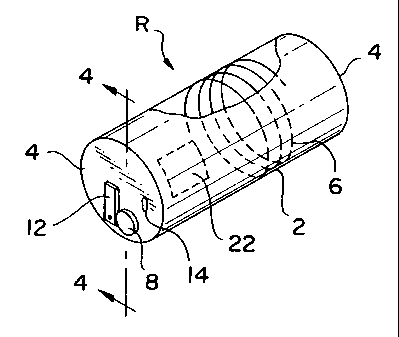
Figure 1 is a perspective view of an emergency vision
device, shown in its deployed inflated form.
Figure 2 is a perspective view of the device shown in Fig.
1 in a compressed stowed form.
Figure 3 is a perspective view of a pouch for storing the
compressed device shown in Fig. 2.
Figure 4 is a cress-sectional view across taken along line
4-4 of Figure 1.
Figure 5 is a schematic circuit for automatic activation of
a light.
DETAILED DESCRIPTION OF THE INVENTION
An emergency vision device R made in accordance with the
present invention is disclosed in Figure 1. The device is in
the form of a collapsible tube 2 made from an airtight fabric or
other suitable materials. Tube 2 is closed off at each end. A
transparent member 4, such as clear plastic sheet, is provided
at each end to allow the user to see through the tube. 'A
helical spring 6 is disposed within the tube 2 to bias the two
members 4 away from each other and expand the tube 2 from its
deflated compressed form to its deployed inflated form. The
-4-

CA 02398218 2002-07-24
WO 01/54976 PCT/USO1/00659
spring 6 may also be disposed outside the tube. The spring 6
can be of any suitable geometric shape. The spring 6
advantageously provides support and rigidity to the tube to
prevent its collapse during use while being handle. The spring
6 is only partially shown for clarity. It should be understood
that the spring stretches from one end of the tube to the other
end and under compression to maintain the tube in the expanded
form. A filter 8 is disposed at one end of the tube to allow
ambient air to fill the volume of the tube as it expands under
the action of the spring 6 after being taken out of its pouch
10. The filter 8 is designed to filter the ambient air during
an emergency smoke situation and provide clear air to fill the
volume of the tube 2. The filter 8 is preferably a HEPA filter.
A light source 12 with its own battery power and switch may be
provided at one end of the tube 2. The switch may provide for
automatic activation of the light 12 when the device R is pulled
out of its pouch 10. The switch may also be operated manually
to conserve power.
Automatic activation of the light may be accomplished in
many ways. One example would be to provide two switches 16 and
18 in series with the light 20, where switch 16 is depressed to
an open state by the Confining wall of the pouch l0,and other
switch 18 is normally on, as best shown in Figure 5. When
device R is taken out of the pouch, the switch 16 will go into a
closed state, causing the light 20 to be energized, since the
other series switch 18 is already in the on state.
_5_

CA 02398218 2002-07-24
WO 01/54976 PCT/USO1/00659
When the device R is not used, it is stowed within the
pouch 10, which is designed to hold the spring 6 in the
compressed position.
When not in use, the device R is compressed to a compact
form, as shown in Figure 2, and is placed within the pouch 10.
To deploy the device R, it is pulled out of the pouch 10,
allowing the spring 6 to expand and inflate the tube 2, without
use of powered pumps or compressed gas. Ambient air is filtered
through the filter 8 and fills up the space within the tube 2.
The light 12, which may be automatically activated, provides
illumination on the object requiring visual visibility to the
operator.
Although the tube 2 is shown with a circular cross-section,
it should be understood that any cross-sectional shape would be
applicable as long as a clear visibility path is provided
through the tube.
In another embodiment, the spring 6 may be omitted. The
ends 4 axe pulled apart from each other to deploy and expand the
tube, drawing air into the interior. A movable flap 13 inside
the tube is disposed across the filter so that air can flow into
the tube through the filter but not flow out so that air is
trapped inside. When the tube fills up with air, the flap 13
prevents the air from escaping to provide the tube with-form and
prevent it from collapsing when handled. A one-way valve with
the direction of flow into the tube, and connected in series
with the filter 8 can also be used in place of the flap 13.
-6-

CA 02398218 2002-07-24
WO 01/54976 PCT/USO1/00659
Although the flap 13 is shown secured to the filter, it should
be understood that it can be installed in any other standard
manner, as long as it is operative to prevent the backflow of
air from inside the tube. A closable port or opening 14 is
provided to allow the air inside the tube to be exhausted when
the tube is deflated for stowage.
The filter 8 may also be integrated into the wall of the
tube 2 in various ways. For example, a portion 22 or the entire
tube wall may be made of filter material.
While this invention has been described as having preferred
design, it is understood that it is capable of further
modification, uses and/or adaptations following in general the
principle of the invention and including such departures from
the present disclosure as come within known or customary
practice in the art to which the invention pertains, and as may
be applied to the essential features set forth, and fall within
the scope of the invention or the limits of the appended claims.

Representative Drawing
A single figure which represents the drawing illustrating the invention.
Administrative Status

2024-08-01:As part of the Next Generation Patents (NGP) transition, the Canadian Patents Database (CPD) now contains a more detailed Event History, which replicates the Event Log of our new back-office solution.

Please note that "Inactive:" events refers to events no longer in use in our new back-office solution.

For a clearer understanding of the status of the application/patent presented on this page, the site Disclaimer , as well as the definitions for Patent , Event History , Maintenance Fee  and Payment History  should be consulted.

Event History

Description Date
Inactive: Expired (new Act pat) 2021-01-29
Common Representative Appointed 2019-10-30
Change of Address or Method of Correspondence Request Received 2018-01-12
Inactive: IPC from MCD 2006-03-12
Grant by Issuance 2005-12-20
Inactive: Cover page published 2005-12-19
Pre-grant 2005-10-06
Inactive: Final fee received 2005-10-06
Notice of Allowance is Issued 2005-05-13
Letter Sent 2005-05-13
Notice of Allowance is Issued 2005-05-13
Inactive: Approved for allowance (AFA) 2005-05-03
Amendment Received - Voluntary Amendment 2005-03-01
Inactive: S.30(2) Rules - Examiner requisition 2004-12-13
Inactive: IPRP received 2003-06-10
Amendment Received - Voluntary Amendment 2003-02-06
Inactive: Cover page published 2002-12-10
Inactive: Inventor deleted 2002-12-06
Letter Sent 2002-12-06
Inactive: Acknowledgment of national entry - RFE 2002-12-06
Application Received - PCT 2002-09-24
Amendment Received - Voluntary Amendment 2002-07-25
National Entry Requirements Determined Compliant 2002-07-24
Request for Examination Requirements Determined Compliant 2002-07-24
All Requirements for Examination Determined Compliant 2002-07-24
National Entry Requirements Determined Compliant 2002-07-24
Application Published (Open to Public Inspection) 2001-08-02

Abandonment History

There is no abandonment history.

Maintenance Fee

The last payment was received on 2005-11-21

Note : If the full payment has not been received on or before the date indicated, a further fee may be required which may be one of the following

  • the reinstatement fee;
  • the late payment fee; or
  • additional fee to reverse deemed expiry.

Please refer to the CIPO Patent Fees web page to see all current fee amounts.

Owners on Record

Note: Records showing the ownership history in alphabetical order.

Current Owners on Record
BERTIL R. L. WERJEFELT
Past Owners on Record
None
Past Owners that do not appear in the "Owners on Record" listing will appear in other documentation within the application.
Documents

To view selected files, please enter reCAPTCHA code :


To view images, click a link in the Document Description column. To download the documents, select one or more checkboxes in the first column and then click the "Download Selected in PDF format (Zip Archive)" or the "Download Selected as Single PDF" button.

List of published and non-published patent-specific documents on the CPD .

If you have any difficulty accessing content, you can call the Client Service Centre at 1-866-997-1936 or send them an e-mail at CIPO Client Service Centre.


Document
Description 
Date
(yyyy-mm-dd) 
Number of pages   Size of Image (KB) 
Representative drawing 2002-07-24 1 5
Cover Page 2002-12-10 1 37
Claims 2002-07-25 8 305
Abstract 2002-07-24 1 56
Description 2002-07-24 7 231
Claims 2002-07-24 5 162
Drawings 2002-07-24 1 13
Description 2005-03-01 7 222
Claims 2005-03-01 7 245
Drawings 2005-03-01 1 15
Representative drawing 2005-11-25 1 10
Cover Page 2005-11-25 1 40
Acknowledgement of Request for Examination 2002-12-06 1 174
Reminder of maintenance fee due 2002-12-09 1 106
Notice of National Entry 2002-12-06 1 198
Commissioner's Notice - Application Found Allowable 2005-05-13 1 162
PCT 2002-07-24 4 173
Fees 2003-01-07 1 32
PCT 2002-07-25 12 490
Fees 2003-12-17 1 32
Fees 2004-12-24 1 26
Correspondence 2005-10-06 1 24
Fees 2005-11-21 1 26
Fees 2006-12-06 1 29
Fees 2008-01-02 1 28
Fees 2008-12-18 1 34
Fees 2009-12-10 1 34
Fees 2010-12-02 1 34