Note: Descriptions are shown in the official language in which they were submitted.
CA 02398272 2008-06-11
Description
BACKGROUND OF THE INVENTION
[0001 ] In industries engaged in producing baked food products such as bread
and pizza,
there is a need to systematically or uniformly feed processing machinery with
portioned
product. These portioned products may be for example, but are not limited to,
bread
dough pieces or pizza dough pieces to be processed into finished product or
loaded into
containers for shipment. Portioned product are typically products that are
accurately
scaled or volumetrically cut into pieces. Some non-limiting examples of types
of products
that are portioned products include pizza dough, bread dough, pie base dough
and bagel
dough. The pieces are typically mixed in bulk and cut or dispensed from the
bulk mix.
[0002] To facilitate the further processing or loading of these portioned
pieces they must
be fed in a stream of product into the processing or loading machinery in a
uniform or
systematic manner. The stream of portioned products can become improperly
sequenced
due to a myriad of different causes. The portioned pieces in the stream will
often come
from the portioning or scaling machines that measure the portioned pieces.
These
machines often do not produce the portioned materials at a constant rate. In
some cases as
these pieces are transported or conveyed, they may lose the proper timing,
spacing or
sequencing. A specific, non-limiting example of this can occur in the case of
bread and
pizza dough, where these portioned pieces may lose their sequence due to a
processing
step where the portioned pieces are rounded into a rough spherical shape.
Similarly, the
portioned pieces of dough often need to be flour coated to nullify their
tackiness and this
can affect spacing. During these rounding and/or flour coating operations, the
portioned
pieces often lose their sequence or space timing.
[0003] If this condition is not corrected, the portioned pieces may cause
difficulties
during downstream manufacturing processes. In some instances, with some pieces
being
too close together, they can drop into the next processing machine as a
"double piece",
thereby causing a jam and a loss of product from the jam and the lag in the
shut down of
the line. In addition to increased delays in production and downtime of the
line, the
possibility of jams during production increases labor costs in man hours to
achieve
production targets and to clear the line.
[0004] Commercially available machines have worked at solving this problem by
having
the portioned pieces drop onto a horizontal roller conveyor where all rollers
would be
rotating in the same direction but each roller would have a decreased
rotational velocity
from the previous roller. The roller conveyor would receive portioned pieces
at the higher
speed end and have the portioned piece travel to the slowest end where it
would drop
from the conveyor as it passes over the last roller. The portioned pieces that
drop onto
this series of rollers would move forward and come in intimate contact with
the already
1
CA 02398272 2008-06-11
slower moving earlier dropped pieces. However, when the portioned piece moves
forward and contacts the back of an earlier portioned piece, it is not able to
push the row
of accumulating earlier portioned pieces forward and therefore it will slip on
the rollers it
is being supported on. As the row of portioned pieces come together and push
each other
forward they tend to cause the row of portioned pieces to move laterally or
shingle
sideways thereby possibly still causing a jam. The rollers of these prior art
machines
being of constant diameter will give no effect to alignment of the portioned
pieces.
Guides are used on the sides of this roller conveyor so as to contain the row
and minimize
shingling but must be kept wide enough to allow for passage of miss shaped or
improperly formed portioned pieces. Thus the guides should be adjusted for
each size of
portioned piece being run, this adjustment is often overlooked. To minimize
the pushing
force of the row of portioned pieces the speed of the rollers is set so that
the portioned
pieces will only come into intimate contact as they approach the discharge
point of the
roller conveyor. This tends to minimize the accumulation effect of the roller
conveyor.
[0005] Thus these machines have several flaws. The short comings of these
machines is
that they were only capable of affecting limited changes in the spacing of the
portioned
pieces and are not capable of stopping and holding pieces for indexing or
synchronized
feeding into subsequent machines. They were also built with a fixed width
roller
conveyor and manually adjustable side guides to accommodate different sized
pieces.
These portioned pieces would often change in size due to differences in final
product size
and weight and were not of a consistent shape. If the pieces were badly miss-
shaped or if
the guides were not properly adjusted, the pieces could become jammed or two
portioned
pieces could become wedged between the guides on the roller conveyor.
[0006] The commercially available machines also require a high degree of
maintenance.
The machines are often required to run in an extremely dusty flour
environment. The
rollers require a high degree of maintenance to keep the flour out of the
bearings. A
further maintenance difficulty arises from the complexity of the drive system
used to
slow or adjust the portioned piece spacing, which utilized gears and chains in
order to
produce the progressively decreasing roller speeds. With all of these gears
and chains
operating in a dusty flour environment the reliability of these machines is
greatly
reduced.
[0007] Thus a need exists for a portioned piece-dispensing machine for
adjusting the
spacing of the portioned pieces for indexing and synchronizing for further
manipulation.
Additionally, a need exists to lessen the required maintenance over
commercially
available portioned piece-dispensing machines.
BRIEF DESCRIPTION OF THE INVENTION
[0008] An object of the instant invention is to provide a portioned piece-
dispensing
machine that adjusts the spacing of the portioned pieces for indexing and
synchronizing
the line of portioned pieces.
2
CA 02398272 2008-06-11
[009] A further object is to provide a portioned piece-dispensing machine that
requires
less maintenance than commercially available portioned piece-dispensing
machines.
[0010] A still further object of the instant invention is to take portioned
pieces and feed
them in a uniform manner or rate to subsequent machines.
[0011] A still further object of the invention is to provide a device and
method for
receiving portioned pieces and putting them in a row, where this row alignment
is
maintained to the point of discharge.
[0012] Yet another object of the invention is it allows for sequential or
synchronized
feeding of portioned pieces.
[0013] Although vibratory conveyors and there design are common knowledge and
are
used extensively in the conveying and often in the metered conveying of
materials, the
instant invention is imparting this motion on portioned pieces of viscous or
semi-viscous,
tacky or coated materials that are not normally moved in this manner. The use
of
vibration coupled with the driving or moving force of the vibration has been
used in
processes that cause powders and light materials to flow to an even layer on
the vibratory
surface and move at an even rate. Still further examples are found for moving
cereals and
powders onto weighing heads. However, the use of vibratory motion to effect
the spacing
of portioned product, especially dough, has not been successfully implemented.
Moreover, the ability to successfully accumulate and then uniformly discharge
portioned
pieces of this nature through the use of vibratory conveyors has not been
previously
proven. These aspects of the invention are achieved through a novel and useful
combination of vibratory motion.
[0014] Some non-limiting examples of the beneficial uses of the instant
invention would
be where portioned pieces are fed to a machine, which would pack the portioned
pieces
into trays. When a full tray is removed or exchanged for an empty tray the
feeding or
placing of portioned pieces would have to be stopped. This feeding system
would be
sequential where a fixed number of pieces would be fed to the processing or
packing
machine then the feed would stop for a given amount of time and then restart.
For this
operation the invention is able to change the spacing of the streams of
portioned pieces,
where these pieces would have to be sequentially fed to a machine which would
pack
these portioned pieces into trays or packages. The instant invention is able
to groups or
places these portioned products that are to be fed in a sequential manner to
match the
loading rate of the loading machine. It may also hold the product for a period
of time
while a full tray or package is removed and replaced with an empty one.
[0015] The manner in which this accumulation and holding is achieved is one
important
aspect of the invention. An analogy can be drawn to the difference between an
escalator,
moving passengers mechanically at a steady set rate that can be varied, and a
playground
slide, utilizing gravity, where the slides gentle slope and curve moves the
passengers into
3
CA 02398272 2008-06-11
one another in a gentle, controlled manner also allowing for accumulation when
no one
gets off. Once the bottom person gets off in the slide example the remaining
persons will
slide down and again into place for the next person to get off. In contrast,
the escalator
must dump its passengers off on top of one another to as it continues to move.
Thus,
during the dwell or accumulation time period, the instant invention would
accumulate
and hold the portioned product and then resume systematic feeding of the
portioned
pieces into the loading machine.
[0016] The invention is directed to a portioned piece spacing apparatus,
comprising an at
least one contoured chute having at least one angle of declination relative to
a horizontal
plane upon which the apparatus is situated. The apparatus includes at least
one vibrating
mechanism coupled to the at least one contoured chute. The apparatus also has
at least
one resilient member supporting the at least one contoured chute. The
vibrating
mechanism vibrates the chute in an at least one direction relative to the
horizontal of the
apparatus such that the portioned pieces are supported on the contoured chute
and
allowed to decelerate in a sequenced manner at a discharge tip of the
contoured chute.
[0017] In the spacing apparatus of claim the at least one angle of declination
can be a
series of declination angles formed by an at least one chute having a constant
radius of
curvature from a receiving area to a discharge tip.
[0018] In the spacing apparatus the at least on declination angle can comprise
a single
declination angle that is constant throughout the contoured chute and is
between about -
degrees and 80 degrees relative to the horizontal plane of the apparatus.
[0019] In the portioned piece spacing apparatus the deceleration of the
portioned pieces
in a sequenced manner is provided by a decreasing driving force transmitted
from the
vibrating mechanism through said at least one resilient member. In the
portioned piece
spacing apparatus the pieces that are supported on the contoured chute are
allowed to
accumulate in a spaced manner proximate to the discharge tip of the contoured
chute.
[0020] The spacing apparatus can have the at least one contoured chute have a
substantially v-shaped contour. The spacing apparatus can also have the at
least one
contoured chute with a substantially u-shaped contour. The spacing apparatus
can have
the at least one contoured chute with a contour comprising curved sides
connected by a
flat bottom. The spacing apparatus can also have the at least one contoured
chute with a
contour comprising sloped sides connected by a flat bottom.
[0021] In the spacing apparatus the at least one angle of declination can be a
constantly
decreasing angle of declination formed by an at least one chute having a
decreasing
radius of curvature. The spacing apparatus can also have the at least one
angle of
declination include a first angle of declination and a second angle of
declination, the
second angle of declination being lower than the first angle. In the spacing
apparatus the
decrease in angle from a first angle to a second angle of declination can be
sufficient
4
CA 02398272 2008-06-11
enough to reduce the speed of the portioned pieces moving from a receiving
area of the
contoured chute to the discharge tip of the contoured chute.
[0022] In the spacing apparatus of the first declination angle can be between
about 0
degrees and about 45 degrees. The first declination angle can also be about 25
degrees.
[0023] The vibration of the contoured chute and the lower second angle of
declination
allows the portioned pieces to accumulate at the exit of the contoured chute
in accurately
spaced manner.
[0024] In the spacing apparatus the second declination angle can be between
about -10
degrees and about 10 degrees. The second declination angle can also be about 0
degrees.
[0025] In the spacing apparatus the portioned pieces can drop from said
discharge tip
from said contoured chute onto a further processing device. The further
processing device
can be an indexing wheel. The further processing device can be a spacing
conveyor.
[0026] In the spacing apparatus the at least one contoured chute can includes
a first
contoured chute coupled to a second contoured chute, the first chute having a
first
portioned piece receiving area and a second portion piece discharge tip and
the second
chute having a second portioned piece receiving area and a second portion
piece
discharge tip. The at least one declination angle can further comprise a first
declination
angle formed by said first contoured chute extending from said first receiving
area toward
said first discharge tip relative to the horizontal plane. The at least one
declination angle
can further comprise a second declination angle formed by said second
contoured chute
extending from said first receiving area toward said first discharge tip
relative to the
horizontal plane. In the spacing apparatus the second angle of declination is
less than said
first angle and said second chute accumulates portioned pieces.
[0027] Also in the spacing apparatus the portioned pieces can be vibrated in a
substantially perpendicular direction relative to the chute to the at least
one resilient
member. The angle of declination can also vary about 20 degrees relative to
the
contoured chute between the receiving area and the discharge tip.
[0028] The instant invention includes another portioned piece spacing
apparatus
comprising an at least one contoured chute having at least one angle of
declination,
receiving area and a discharge tip with a vibrating mechanism coupled to the
at least one
contoured chute. The apparatus having at least one resilient member coupled at
a resilient
member angle to the at least one contoured chute and supporting the at least
one
contoured chute. In the apparatus the vibrating mechanism vibrates the at
least one
contoured chute vibrates in at least one direction relative to the horizontal
of the
apparatus and the portioned pieces are supported on the contoured chute and
allowed to
decelerate in a sequenced manner at a discharge tip of the contoured chute.
CA 02398272 2008-06-11
[0029] In the spacing apparatus the at least on delineation angle can
comprises a single
declination angle that is constant throughout the contoured chute and is
between about -
degrees and 80 degrees relative to the horizontal plane of the apparatus.
[0030] The portioned pieces can accumulate in a spaced manner proximate to a
discharge
tip of the contoured chute. In the portioned piece spacing apparatus the
deceleration of
the portioned pieces in a sequenced manner can be provided by decreasing the
driving
force transmitted from the vibrating mechanism through said at least one
resilient
member
[0031] In the portioned piece spacing apparatus the pieces that are supported
on the
contoured chute can be allowed to accumulate in a spaced manner proximate to
the
discharge tip of the contoured chute.
[0032] In the spacing apparatus the at lest one resilient member coupled at a
resilient
member angle can comprise a first resilient member at a first resilient member
angle. The
first resilient member angle can be between about 0 and about 80 degrees. The
first
resilient member angle can also be between about 20 and about 45 degrees.
[0033] In the spacing apparatus the at lest one resilient member can comprise
a second
resilient member at a second resilient member angle. The second resilient
member angle
can be equal to the first resilient member angle. The second resilient member
angle can
be between about 10 and about 80 degrees. The second resilient member angle
can also
be between about 20 and about 45 degrees.
[0034] In the spacing apparatus the at lest one resilient member can comprise
a third
resilient member at a third resilient member angle. The third resilient member
angle can
be equal to the first resilient member angle. The third resilient member angle
can be
between about 10 and about 80 degrees. The third resilient member angle can be
between
about 20 and about 45 degrees.
[0035] In the spacing apparatus the portioned pieces can be dropped from said
discharge
tip of said contoured chute onto a further processing device. The further
processing
device can be an indexing wheel. The further processing device can be a
spacing
conveyor. The further processing device can be an indexing device.
[0036] In the spacing apparatus the at least one contoured chute can include a
first
contoured chute coupled to a second contoured chute, the first chute having a
first
portioned piece receiving area and a first portioned piece discharge tip and
the second
chute having a second portioned piece receiving area and a second portioned
piece
discharge tip. The first contoured chute can form a first angle relative to
the horizontal
plane of the apparatus from said first portioned piece receiving area to said
first portioned
piece discharge tip. The second contoured chute can form a second angle
relative to the
horizontal plane of the apparatus from said second portioned piece receiving
area to said
6
CA 02398272 2008-06-11
second portioned piece discharge tip. The second angle can be less than said
first angle
and said second contoured chute can accumulate portioned pieces.
[0037] The invention includes a method of indexing portioned product,
comprising the
method steps of: vibrating a contoured chute with a longitudinal axis,
providing portioned
pieces of product to an receiving area on said contoured chute, vibrating said
product at
an at least one angle so as to provide a movement vector comprised of at least
one
forward component relative to the chute. The method includes aligning said
portioned
pieces along said contoured chute and removing said portioned pieces in an
indexed
manner.
[0038] The method can further comprise the method step of varying the said at
least one
angle at which said portioned pieces are vibrated by changing an angle of a
resilient
member attached to said contoured chute.
[0039] The method can further comprise the method step of varying the said at
least one
angle at which said portioned pieces are vibrated by changing a declination
angle of said
contoured chute.
[0040] The method can further comprise the method step of varying the said at
least one
angle at which said portioned pieces are vibrated by changing an angle of a
resilient
member attached to said contoured chute and changing a declination angle of
said
contoured chute.
[0041 ] The invention also includes a still further portioned piece spacing
apparatus,
comprising an at least one contoured chute having a longitudinal center line,
an at least
one angle of declination, an receiving area and an discharge tip with a
vibrating
mechanism coupled to the at least one contoured chute. An at least one
resilient member
is included, supporting the at least one contoured chute. The vibrating
mechanism
vibrates the chute such that the portioned piece moves upward and forward
relative to the
longitudinal centerline of the at least one contoured chute and the portioned
pieces are
supported on the contoured chute and allowed to decelerate in a sequenced
manner at a
discharge tip of the contoured chute.
[0042] Moreover, the above objects and advantages of the invention are
illustrative, and
not exhaustive, of those that can be achieved by the invention. Thus, these
and other
objects and advantages of the invention will be apparent from the description
herein, both
as embodied herein and as modified in view of any variations which will be
apparent to
those skilled in the art.
7
CA 02398272 2008-06-11
DESCRIPTION OF FIGURES
[0043] FIG. 1 shows a side view of an exemplary embodiment of the invention
utilizing a
single piece, continuous contoured inclined chute with one angle of
declination
depositing onto the bottom spacing conveyor. [0044] FIG. 2--shows a front view
of the first embodiment of FIG. 1 utilizing a single
piece continuous contoured chute with 1 angle of declination depositing onto
the bottom
spacing conveyor.
[0045] FIG. 3 shows a side view of an exemplary embodiment with one piece
contoured
chute with two declination angles depositing onto the bottom spacing conveyor.
[0046] FIG. 4 shows a side view of a exemplary embodiment with two piece
contoured
chute with two declination angles depositing onto the bottom spacing conveyor.
[0047] FIG. 5 shows a side view of an exemplary embodiment with a one piece i
contoured chute depositing into a pocketed indexing wheel.
[0048] FIG. 6 shows a front view of the embodiment of FIG. 5.
[0049] FIG. 7 shows a side view of an exemplary embodiment with one piece
contoured
chute of 2 declination angles depositing into the pocketed indexing wheel.
[0050] FIG. 8 shows a side view of an exemplary embodiment with a two piece
contoured chute with two declination angles depositing onto the pocketed index
wheel.
[0051 ] FIGS. 9A and 9B show exemplary contours for the contoured vibratory
chutes of
the exemplary embodiments depicted.
[0052] FIG. 10 shows a front view of the exemplary embodiment of FIG. 11,
having a
single piece continuous contoured chute with two angles of declination
depositing onto
the bottom spacing conveyor.
[0053] FIG. 11 shows a side view of an exemplary, having a single piece
continuous
contoured chute with two angles of declination depositing onto the bottom
spacing
conveyor.
8
CA 02398272 2008-06-11
DETAILED DESCRIPTION OF THE FIGURES AND THE EXEMPLARY
EMBODIMENTS OF THE INVENTION
[0054] FIG. 1 shows a side view of an exemplary embodiment of the invention
utilizing a
single piece, continuous contoured chute with one angle of declination. The
exemplary
embodiment shown in the side view comprises a main frame 1 that supports and
provides
attachment for all of the components of the machine. The machine operates by
having
portioned pieces 1000 drop onto the receiving area 20 of the vibratory
contoured chute 2
at the upper right end of the vibratory contoured chute 2 in FIG. 1.
[0055] Vibratory contoured chute 2 is typically set at an downward incline, as
seen in the
Figures of the application, from right to left to provide for motion due to
gravity as well
as the motion that may be generated by the vibratory motion of the chute.
However, this
is not a limitation of the instant invention and where reference is made to
motion from
right to left it can equally be made to motion from left to right without
departing from the
spirit of the invention. Typical angles of declination of the vibratory
contoured chute 2
are from about -10 to about 80 degrees from the horizontal relative to the
machine. The
angle of declination of the exemplary embodiment of the vibratory contoured
chute 2 of
FIG. 1 is about 25 degrees.
[0056] For example, the contoured chute 2 can be suspended upon two vibratory
membrane springs acting as resilient members 3 are set at two different angles
to the
common section of the contoured chute 2. The membrane springs are one example
of the
resilient member 3, the membrane springs allowing for specific control of the
vibration in
one plain. Coil springs and other springs could be used, but may result in
additional
unwanted motion, making synchronization difficult.
[0057] The length of contoured chute 2 is variable and typically determined by
the
amount of portioned pieces 1000 that must be spaced. As an example where the
portioned
pieces 1000 being fed onto the contoured chute 13 are reasonably spaced with
only an
occasional portioned pieces 1000 that may be too closely spaced the length of
the
contoured chute 2 may be held to 2 feet in length. Where the portioned pieces
1000 may
be fed from dump conveyors or trays the spacing and feed rate could have a
large degree
of variation. This may have a feed rate where portioned pieces 1000 may be
deposited
onto the contoured chute 2 at a high rate for a short period of time and then
for a
relatively equal length of time no portioned pieces 1000 would be deposited.
For this
application a long contoured chute 2 would be needed so that the pieces could
accumulate
or be stored on the contoured chute 2 and then be evenly fed out through, for
example, a
spacing conveyor belt 13 or pocketed indexing wheel 33, as further described
below.
There may also be a need to store or accumulate portioned pieces 1000. An
example
would be where subsequent machines would need to stop and then restart. In
this instant
the spacing conveyor belt 13 or pocketed indexing whee133 may stop and the
contoured
chute 2 would be able to continue to accept and accumulate portioned pieces.
When the
subsequent machines were able to again accept portioned pieces the spacing
conveyor
9
CA 02398272 2008-06-11
belt 13 or pocketed indexing wheel 33 would restart and remove portioned
pieces from
the contoured chute 2.
[0058] The shape of the contoured chute 2 is typically in the form of a
trough. It is
tapered from a wider section at the top to narrower at the bottom but
typically the same
width through the length of the contoured chute 2, as more clearly seen in
FIGS. 2, 6, and
9, which show end views of the exemplary embodiments and the chutes of the
exemplary
embodiments. This provides a means by which the portioned pieces 1000 can
travel
towards the longitudinal centerline of the contoured chute 2 when the
portioned pieces
1000 drop onto the receiving area 20 of the contoured chute 2. The taper or
shape of the
contoured chute 2 also helps ensure that as the portioned pieces travel along
the
longitudinal centerline of the contoured chute 2. The narrowing of the
vibratory
contoured chute 2 will move the portioned pieces 1000 into line. That is a
relatively
straight line without having the portioned pieces 1000 move laterally out of
line as they
come together during accumulation at the exit of the chute.
[0059] The taper or shape of the contoured chute 2 also allows for portioned
pieces 1000
of different sizes to be accommodated without the need for width or side
guides or
adjustment thereof. This accommodates portioned pieces 1000 of all sizes and
allows
them to remain in a reasonably straight line. This vibratory contoured chute 2
may also be
set, or may be set with a final portion of the chute, at horizontal or a very
slightly
inclined, where the portioned pieces 1000 would travel upwards to the
discharge end 21
due to the vibratory motion of the contoured chute 20.
[0060] In instant invention vibration is used as a means of moving or
conveying a
portioned piece down along the vibratory contoured chute 2. This is set in
motion by a
vibrator 7, which can for example be a reciprocating piston type vibrator
driven by
compressed air. Other examples of vibrators that can be employed to impart
this vibratory
force or motion include, but are not limited to, compressed air driven
vibrators;
mechanically driven reciprocating or offset rotating masses; and electrical or
magnetic
vibrators.
[0061] In the exemplary embodiment shown the angle of the resilient member 3
relative
to the contoured chute 2 causes the portioned pieces 1000 to be carried
forward as the
vibratory motion of the contoured chute 2 goes up and to the left relative to
the main
frame 1 in FIGS. 1, 3,4,5,7,8 and 11. When the vibrative motion of the
contoured chute 2
goes down and to the right the momentum of the moving portioned piece 1000
will cause
it to continue to move up and to the left as it looses contact with the chute.
As the moving
portioned piece 10001osses upward motion due to gravity it will start to drop
until it
again strikes the surface of the contoured chute 2. During the period of time
that the
portioned piece 1000 is being driven upward (and to the left by the motion of
the chute)
plus the time while it is airborne the moving portioned piece 1000 is
constantly moving
to the left. The actual operating motion is rapid and so the moving portioned
piece 1000
appears to be vibrating or floating constantly to the left. 10
CA 02398272 2008-06-11
[0062] The overall effect on the moving portioned piece 1000 is that it will
be driven
down the vibratory contoured chute 2 so long as the speed or rate and
magnitude or
amplitude of vibratory motion is great enough to allow for the moving
portioned piece
1000 to loose contact with the contoured chute 2 during application of the
vibratory
motion. It is the angle of the movement of the moving portioned piece 1000
relative to
the moving surface that the product travels, in this case the vibratory
contoured chute 2,
which allows the instant invention to operate. In the unit as depicted in FIG.
1, the
vibratory motion is perpendicular to the at least one resilient member 3. In
additional
embodiments, the at least one resilient member 3 can be a coil spring and the
motion of
the spring would be parallel, or perpendicular, to the center line of the
spring.
[0063] The motion of the material is principally controlled by the angle that
the at least
one resilient member 3 makes to the chute. As previously stated when the
resilient
member 3 is mounted substantially perpendicular to the contoured chute 2, as
in FIG. 1,
the motion imparted will be predominantly lateral with little to no vertical
motion. As the
resilient member 3 is brought closer to being parallel to the contoured chute
2 the degree
of vertical motion increases and the amount of lateral motion decreases.
Depending on
various factors such as the angle of declination of the contoured chute 2,
type of material
to be moved, desired speed of the material to be moved and desired driving
force to be
exerted onto the product, an appropriate angle for the attachment of the at
least one
resilient member 3 to the contoured chute 2 can be determined.
[0064] The lower the viscous nature of the portioned pieces 1000 the greater
the required
amplitude of vibration required as the tacky portioned pieces 1000, for
example dough,
has a tendency to absorb the vibration and flow laterally when not constrained
by the
sides of the chute and or adjacent portioned pieces 1000. As the portioned
piece 1000
becomes more viscous, the ability to flow or absorb vibration decreases and
therefore the
amplitude of vibration required for a given speed will decrease.
[0065] The speed or frequency of vibration is also significant in that if the
vibration or
frequency is very high the portioned piece 1000 will not be able to utilize a
significant
portion of the vibration movement due to the lack of time for it to fall due
to the force of
gravity. In the case of overly high vibratory frequencies the portioned piece
may absorb
the major portion of the vibration and have little movement. A slower
vibration frequency
of the same amplitude would allow the portioned piece to drop a greater
distance prior to
being absorbed in the next upward and to the left motion of the contoured
chute 2 thereby
with the same amount of vibration absorption travel further than with a higher
vibrative
frequency.
[0066] The required speed of portioned piece travel may also be influenced by
the size of
the pieces and the rate that they must be moved at. An example being, if one
were
spacing bread dough pieces of 4 inch diameter at 120 pieces per minute the
rate of travel
could not be less than 480 inches per minute but when at running bread dough
pieces at
40 pieces per minute the rate of 480 inches per minute would be too high. The
typical
11
CA 02398272 2008-06-11
movement speed of the chute 2 is about two to four times the length of
portioned product
diameter multiplied by the average delivery rate of portioned pieces, but may
be higher or
lower depending on the product. Thereby allowing the portioned pieces to be
quickly
taken away from the receiving area 20.
[0067] Another example is a case where it is desirable to "levitate" the
portioned pieces
1000, through the use of vibratory motion, to be transferred with a low
pushing force so
that product may easily float into position. In this case, resilient member 3
may be
mounted at an angle substantially parallel or perpendicular to the contoured
chute 2.
Where aggressive movement is required the at least one resilient member 3 may
be
mounted at a 45 degree angle to the contoured chute 2. For instance, in the
exemplary
embodiment of FIG. 11, unlike the embodiment of FIG. 1, the at least one
resilient
member 3 comprises two resilient members that are mounted at dissimilar
angles. The
angle of the resilient members 3, on the right or where, in this case, the
receiving area 20
of the portioned pieces 1000 are deposited, is at an angle of approximately 45
degrees.
This provides for quick and aggressive movement of the portioned pieces 1000
to the left
and down the vibratory contoured chute 2. The second resilient member is at a
lower
angle relative to the first for a slower, less aggressive forward movement of
the portioned
pieces 1000.
[0068] This placement of the resilient member 3 at the specified angles on the
one
vibratory contoured chute 2 provides for a strong aggressive movement of the
portioned
pieces 1000 when deposited onto the contoured chute 2. This being beneficial
in taking
the portioned piece 1000 away from the receiving area 20 of the contoured
chute 2
allowing for the deposit of the next portioned piece 1000 with out
interference of the
previous portioned piece 1000. If this movement is too slow when two or more
portioned
pieces 1000 come in close proximity to each other, they could fall one atop
the other.
This would result in a double portion, causing a double product or a jam in a
subsequent
machine. Thus the angles of the resilient members relative to the chute and
the angles of
the chute are important to the invention.
[0069] As the portioned pieces 1000 travel to the left and down the contoured
chute 2 the
speed of the portioned pieces 1000 is reduced. This decrease in velocity and
driving force
allows the portioned pieces 1000 to come together in the lower left portion of
the
contoured chute 2. As the portioned pieces 1000 approach the discharge tip 20a
of the
vibrating contoured chute 2 the driving force on the portioned piece 1000 is
minimal and
therefore the pieces can collect to the point where there discharge speed may
be best
controlled by the speed of the spacing conveyor belt 13.
[0070] FIG. 3 shows an exemplary embodiment with one piece contoured chute
with two
declination angles depositing onto the bottom spacing conveyor. The vibratory
contoured
chute 2 may be made of various sections, which are welded or joined to form a
one piece
contoured chute with different angles of declination over the length of the
contoured
chute 2. FIGS. 4 and 8 show side views of two additional exemplary
embodiments. FIG.
12
CA 02398272 2008-06-11
4 shows a side view of an exemplary embodiment with two piece contoured chute
with
two declination angles depositing onto the bottom spacing conveyor. This would
result in
multiple chutes or portions of chute with a respective sub-section receiving
area and
discharge tip, for example a second chute would have a second receiving area
and a
second discharge are and tip. An example of this can be seen in FIG. 4 and
also in FIG. 7
where the first portion of the inclined contoured chute 2, where the portioned
pieces 1000
are first deposited, would have the greatest degree of declination so as to
accelerate
portioned pieces 1000 downward to the discharge tip 20a point of the second
portion of
chute 2 as quickly as possible. At the middle or end of the contoured chute 2
a separate
chute is added so that the degree of declination would decrease so as to
produce a lower
velocity zone as compared to the previous section of higher declination. The
second chute
would have a receiving area and in communication with a discharge tip of the
first chute.
[0071] FIGS. 3 and 7 show other exemplary embodiments where multiple changes
in
declination angle would be present in over the length of the contoured chute
2. These
exemplary embodiments have a bend in them changing the declination angle. This
can
also include where the contoured chute 2 would be of a radiused design or
continuously
changing degree of declination. An example of a constant radius contoured
chute 2 would
be where the discharge area 20a would be approaching horizontal and as the
chute goes
from discharge point to receiving point the angle of declination of the chute
becomes
continuously greater, approaching or passing 25 degrees. One such cross-
sectional shape
can be shown as a constant radius would be defined where all lines drawn
perpendicular
to the contoured chute 2 would meet at a common intersection point. A further
shape
could include a non-continuous radius would be where the radius of the
contoured chute
would change over the length of the chute or as one moves from the discharge
tip 20a to
the receiving area 20. An example of this type of chute would be where the
discharge tip
of the contoured chute 2 would be approximately horizontal with the contoured
chute
quickly going to inclined. The radius of curvature here would be quite small
as compared
to the radius of curvature at the receiving area of the contoured chute 2. At
the receiving
area 20 of the contoured chute 2 the radius of curvature would be greater and
therefore
the shape being flatter or not as sharply curved as in the discharge tip 20a.
[0072] Whether it is through the use of separate sections or bending a single
piece chute,
the second declination angle or second vibratory chute section modify the
movement of
the moving portioned pieces 1000 by varying the degrees of upward motion
imparted in
them. If the angle of the contoured chute or chutes 2 and the angle of the
resilient
members 3 is not varied, then the vibratory motion of the contoured chute 2
would be
constant and therefore the higher speed desired to initially move the piece
would decrease
the ability of the portioned pieces 1000 to gently come together. The greater
aggressive
force would cause the portioned pieces 1000 down and onto the spacing conveyor
belt 13
too quickly. Instead the ability to collect the portioned pieces is improved
by varying the
angle of declination. This is what allows randomly fed pieces to come together
and be fed
out in a uniformly timed sequence.
13
CA 02398272 2008-06-11
[0073] If this contoured chute 2 were to be used without the decreasing
driving force
imparted on the moving portioned pieces 1000 in conjunction with a pocketed
indexing
wheel 33 the portioned pieces 1000 would effectively be forced into a pocket
that is
formed in the pocketed indexer whee133 between the dividers 34. In the event
that a
pocket comes open early there is a high degree of probability that once the
first portioned
piece 1000 enters the pocket a second piece would be forced into this pocket
resulting in
a"double", a condition where two portioned pieces 1000 are delivered or
metered as one
from the invention and into a possible subsequent machine. The use of, for
example, a
two degree chute declination at the end of the single piece vibratory
contoured chute 2 or
in the second vibratory contoured chute allows for the appropriate
accumulation of the
portioned pieces. As mentioned it is also possible to accomplish this with a
chute with
multiple bends or changes of the angle of declination along or through an
arced trough
where the arc could be a constant radius or a parabolic curve.
[0074] Also, this reduction in speed can be accomplished by using dissimilar
angles of
attachment for the at least one resilient member 3, for lower forward
components of the
motion used to drive the moving portioned pieces 1000 at the discharge end 20a
of the
vibrating contoured chute 2 and therefore more uniform placement of portioned
pieces
1000 onto a spacing conveyor 13 or pocketed indexing wheel 33.
[0075] The angle of declination of the contoured chute 2, vibrator frame 9 and
all
previously mentioned parts can be adjusted by loosening, for instance,
threaded fastener
12 and allowing vertical adjustment brackets 10 to move relative to the
horizontal
adjustment brackets 11.
[0076] The vibratory motion of the contoured chute 2 causes the portioned
piece 1000 to
travel down the contoured chute 2 going, or relative to the figures, from the
upper right
side to the lower left side of the contoured chute 2. At the bottom of the
contoured chute
2 the portioned piece 1000 may be deposited onto, for example a spacing
conveyor 13 or
a pocketed indexing wheel 33. These combinations are further discussed in
relation to
FIGS. 1 thru 8 and 11.
[0077] The contoured chute 2 can deposit to a further metering processing
machine, for
example either a spacing conveyor belt 13 or an indexing whee133. From the
spacing
conveyor belt 13 or indexer wheel 33 the portioned product 1000 can then be
deposited
into a still further subsequent processing machine in a spaced manner. The
combination
of the vibrating contoured chute 2, with appropriately set angles of
attachment of the at
least one mount plates 4 and the resilient members 3 or in combination with
changing
angles of declination in the chute, allow the moving portioned pieces 1000 to
be fed to
the spacing conveyor or rotating pocketed wheel as the conveyor or wheel
requires the
product. Through the appropriate adjustment of the angles of the at least one
resilient
member 3 which can be in adjusted alone or in combination with changing angles
of
declination in the chute 2, allow the moving portioned pieces 1000 to be fed
to the
spacing conveyor or rotating pocketed wheel as the conveyor or wheel requires
the
14
CA 02398272 2008-06-11
product. Thus the instant invention brings about the desired effect of
holding,
accumulating and uniformly feeding portioned pieces.
[0078] FIG. 11 shows a side view of a still further exemplary embodiment with
a one
piece vibratory contoured chute having two declination angles depositing onto
the bottom
spacing conveyor. The exemplary embodiment shown in the side view of FIG. 11
comprises a main frame 1 that supports and provides attachment for all of the
components of the machine. The machine operates by having portioned pieces
1000 drop
onto the receiving area 20 of the contoured chute 2 at the upper right end of
the contoured
chute 2 in FIG. 11.
[0079] Contoured chute 2 is typically set at an downward incline, as seen in
the Figures
of the application, from right to left to provide for motion due to gravity as
well as the
motion that may be generated by the vibratory motion of the contoured chute 2.
However,
this is not a limitation of the instant invention and where reference is made
to motion
from right to left it can equally be made to motion from left to right without
departing
from the spirit of the invention. Typical angles of declination of the
vibratory contoured
chute 2 are from about 0 to about 80 degrees from the horizontal relative to
the main
frame 1. The angle of declination for the first portion of the of the
exemplary
embodiment of the vibratory contoured chute 2 of FIG. 11 is about 25 degrees
from the
horizontal relative to the main frame 1. A second portion of the contoured
chute 2 in the
exemplary embodiment shown in FIG. 11 has a variation in the declination
angle, such
that the declination angle decreases to about between minus ten degrees and
ten degrees
from the horizontal relative to the main frame 1. A preferred angle of
declination for the
second portion of the chute 2 is zero degrees or in line with the horizontal
of the main
frame 1. The vibratory contoured chute 2 sloping downward to, for example, the
spacing
conveyor belt 13 or pocketed indexing wheel 33. This angle may be increased as
required
to provide additional gravitational pull so as to move portioned pieces 1000
down the
inclined contoured chute 2 faster or at a greater velocity as compared to when
contoured
chute 2 would be at a lower angle from the horizontal. Typically this angle
could go
above 25 degrees but at higher declinations, such as above 30 degrees, the
portioned
piece 1000 may start to roll down the declined vibratory contoured chute 2
depending on
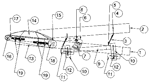
the product. The declination angle of contoured chute 2 may also be reduced to
horizontal
or inclined upward to the discharge tip 20a or to the spacing conveyor belt 13
or pocketed
indexing wheel. This would be possible for all types or shapes of contoured
chutes 2.
[0080] The shape of the contoured chute 2 is typically in the form of a
trough. It is
tapered from a wider section at the top of the chute to narrower section at
the, the bottom
being of consistent or continuous width throughout with the sides tapering to
a higher
angle of inclination or "narrowing" along the length of the contoured chute 2,
as more
clearly seen in FIGS. 6 and 9 which show an end view of an exemplary
embodiment and
views of other alternate designs. This provides a means by which the portioned
pieces
1000 can travel towards the longitudinal centerline of the contoured chute 2
when the
portioned pieces 1000 drop onto the receiving area 20 of the contoured chute
2. The taper
CA 02398272 2008-06-11
or shape of the contoured chute 2 also helps ensure that as the portioned
pieces travel
along the longitudinal centerline of the contoured chute 2 the pieces will be
kept in line.
That is a relatively straight line without having the portioned pieces 1000
move laterally
out of line as they come together during accumulation at the exit of the
contoured chute
2.
[0081 ] The taper or shape of the contoured chute 2 also allows for portioned
pieces 1000
of different sizes to be accommodated without the need for width or side
guides or
adjustment thereo This accommodates portioned pieces 1000 of all sizes and
allows
them to remain in a reasonably straight line. This vibratory contoured chute 2
may also be
set horizontal or at a slight incline, at the discharge tip 20a is inclined
and still allow for
travel or movement of the portioned pieces 1000 due to the vibratory motion of
the
contoured chute 20.
[0082] In instant invention vibration is used as a means of moving or
conveying a
portioned product 1000 down along the vibratory contoured chute 2. This is set
in motion
by a vibrator 7, 7a, which can for example be a reciprocating piston type
vibrator driven
by compressed air. As compressed air is delivered to the vibrator the piston
will start to
reciprocate within the housing. This reciprocating motion causes a resulting
reciprocating
force to be transmitted through to the vibratory contoured chute 2 to which
the vibrator 7
is rigidly mounted. Other non-limiting examples of vibrators that can be
employed to
impart this vibratory force or motion include other styles of air driven
vibrators;
mechanically driven reciprocating or offset rotating masses; and electrical or
magnetic
vibrators.
[0083] This vibratory force generated by the vibrator 7 will then translate
into vibratory
motion through deflection of an at least one resilient member 3. In the
exemplary
embodiment of FIG. 11, two resilient members 3 are shown. These resilient
members 3
are also used to connect the vibrating contoured chute 20 to the vibrator
frame 9 by the
use of chute mount plates 4 and vibratory frame mount plates 5. The angle of
the resilient
member 3 is set as perpendicular or at an angle other than perpendicular to
the contoured
chute 2. The vibratory contoured chute 2 vibrates when the vibrator 7,7a
imparts
vibratory force to the contoured chute 2 which is attached to vibrator frame 9
through
resilient member 3, mount plates 4 and frame mount plates 5. When the
resilient
members 3 are set at perpendicular angles relative to the vibratory chute 2
the resulting
vibratory motion will be roughly parallel to the longitudinal axis of the
chute. If the
resilient members 3 are set at an angle to the chute, for example 20 degrees
off of
perpendicular with the contoured chute 2, then the vibratory motion will be a
combination of two vectors. One vector being parallel to the longitudinal axis
of the
contoured chute 2, the other vector being perpendicular to the longitudinal
axis of the
contoured chute 2.
[0084] The exemplary embodiments of the instant invention shown in FIGS. 1, 4
and 11
include a spacing conveyor. The combination of the vibratory contoured chute 2
and
16
CA 02398272 2008-06-11
spacing conveyor belt 13 allow the portioned pieces 1000 to be fed in a
uniform sequence
from the contoured chute 2 to the spacing conveyor belt 13 and uniformly fed
into
subsequent processing machinery. The speed and operation of the spacing
conveyor belt
13 determines how close together the portioned pieces 1000 may accumulate. The
best
operation being where the portioned pieces 1000 are allowed to accumulate one-
fourth to
one-third of the way up the inclined contoured chute 2. This would ensure that
the
portioned pieces 1000 on the spacing belt would form one uninterrupted line
and
therefore drop off of discharge the end of the spacing conveyor belt 13 at a
consistent
interval basis.
[0085] As the portioned pieces 1000 are deposited on the receiving area 20 of
the
contoured chute 2 they will travel down the contoured chute 2 toward the
spacing
conveyor belt 13 which is formed to a parabolic or cupped shape by the use of
contour
plates 14 in the preferred embodiment. The contoured plates 14 causing the
spacing
conveyor belt 13 to form to the required cupped or parabolic shape as the belt
passes
onto/between and through the contoured plates 14. The belt will go back to its
original
flat profile or shape as it passes beyond the contour plates and approaches
the take up
pulley 16.
[0086] The spacing conveyor belt 13 taking the portioned pieces 1000 from the
inclined,
contoured chute 2 with the portioned pieces 1000 remaining in intimate contact
with the
adjacent portioned pieces 1000 in a reasonably straight line. The spacing
conveyor belt
13 carries these portioned pieces 1000 to the end of the spacing conveyor belt
13 where
they are allowed to pass over the take up pulley 16 and pass onto or fall into
the
subsequent processing machine.
[0087] In alternate applications the contour plates 14 could be substituted by
rollers
rotating about a fixed axis, where the roller axis is parallel to the upper
portion of the
contour of the spacing conveyor belt 13 and perpendicular to the direction of
the spacing
conveyor belt 13 travel. The contour of the spacer conveyor belt 13 being able
to capture
and hold the portioned pieces 1000 in line since the portioned pieces 1000
would be
traveling down and collecting on the contoured chute 2 prior to the point
where the
portioned pieces 1000 transfer onto the spacing conveyor belt 13.
[0088] Through the accumulation of the portioned pieces 1000 on the contoured
chute 2
and the vibratory motion thereof, a slight pressure would be present tending
to push the
portioned pieces 1000 toward the spacing conveyor belt 13 or pocketed indexing
wheel
33. The resulting pushing force could otherwise cause a lateral shingling
effect on the
portioned pieces 1000 were it not for the contour of the spacing conveyor belt
13. The
spacing conveyor belt 13 taking the shape of the contour inducing means as
previously
described by the tension induced into the spacing conveyor belt 13 by the
opposing force
of the drive pulley 15 and the take-up pulley 16. Position of the drive pulley
15 and take-
up pulley 16 may be reversed in alternate installations. Tension of the
rollers being
maintained by take up pulley adjusting rods 17 and drive pulley adjusting rods
18 and
17
CA 02398272 2008-06-11
adjustment nuts 19. In this application the drive pulley 15 is a commercially
available
motorized pulley where the motor and any or all required gears used to
transmit the
rotational motion of the motor to the outside of the pulley is contained
inside the pulley.
This motorized pulley was used as the most effective way to drive the spacing
conveyor
belt 13 based on simplicity, sanitation standards or clean operation, and
compact self
contained design. It would be possible to also drive this pulley from external
sources.
[0089] Through rotation of the drive pulley 15 the spacing conveyor belt 13
will travel
over the surfaces of the contour plates 14 or there equivalent. The portioned
pieces 1000
deposited from the contoured chute onto the spacing conveyor belt 13 will
thereby be
carried on the surface of the spacing conveyor belt 13 and as the spacing
conveyor belt 13
travels to and around the take-up pulley 16 the portioned piece 1000 will fall
from the
edge and into the subsequent machine and or conveyor.
[0090] The velocity of the spacing conveyor belt 13 can be adjusted, thereby
maintaining
the accumulation of the portioned pieces 1000 on the contoured chute 2 and the
resulting
continuous stream of portioned pieces 1000 which transfer from the contoured
chute 2 to
the spacing conveyor belt 13. This continuous stream of portioned pieces
moving on the
spacing conveyor belt and over the end of the take up pulley 16 ensures the
even drop
rate to the subsequent processing machine. The combination of declined
contoured chute
2 with spacing conveyor belt 13 also allows for sequential or synchronized
indexing of
the pieces to machines which may be used to load or package the portioned
pieces 1000.
The spacing conveyor 13 may also be used to provide synchronized feeding or
loading
with dwell time periods. In the case of a required dwell time period, the
spacing conveyor
belt 13 can be stopped which will allow for accumulation of portioned pieces
1000 on the
declined contoured chute 2. Once feeding of pieces is to resume the spacing
conveyor
belt 13 is started. A sensor at the discharge end of the bottom spacing
conveyor may be
used to allow for synchronized feeding of pieces.
[0091] Typical applications may be where: the spacing conveyor belt 13 will
run
allowing portioned product to pass from the contoured chute 2 onto the spacing
conveyor
belt 13. As the spacing conveyor belt 13 moves forward it will carry the
portioned pieces
1000 to the end of the spacing conveyor belt 13 where as the spacing conveyor
belt 13
goes around the take up pulley 16 the portioned pieces 1000 will fall from the
spacing
conveyor belt 13. To allow for indexed feed of the portioned pieces 1000 from
the
invention or to allow subsequent processing machines a means of sensing the
presence or
feed rate of approaching portioned pieces 1000 a sensor, for example a photo
scanner,
would be placed at the discharge end of the spacing conveyor belt 13 so that
the sensor
can detect the presence of a portioned piece 1000 as well as detect the gap or
absence of a
portioned piece 1000 when it drops off of the end of the spacing conveyor belt
13 as it
goes over the small take up pulley 16.
[0092] The sensor would operate in that when the receiving or down stream
machine
receiving portioned pieces 1000 requires only one more portioned piece 1000
the sensor
18
CA 02398272 2008-06-11
would open the electrical circuit controlling the movement of the spacing
conveyor belt
13 when the sensor senses a space or effectively that the last required
portioned piece
1000 has fallen from the spacing conveyor belt 13. The sensor would continue
to hold the
electrical circuit open until the receiving or down stream machine calls or
demands the
flow of portioned pieces 1000 to resume.
[0093] It may be required to feed groups or a specified number of portioned
pieces 1000
to the receiving or down stream machine. In this application a sensor (not
shown), such
as a photo scanner, would be placed at the end of the spacing conveyor belt 13
so that the
sensor can detect the presence and dropping of a portioned piece 1000 as well
as detect
the gap or absence of when a portioned piece 1000 drops off of the spacer
conveyor belt
13 as it goes over the take up pulley 16. The sensor would then count the
pieces being
dropped and stop for a preset time after the count allotment has been reached.
[0094] FIGS. 5, 7 and 8 show side views of further exemplary embodiments with
indexing wheels.
[0095] FIG. 5 shows a side view of an exemplary embodiment with a one piece
inclined
contoured chute depositing into a pocketed indexing wheel. The vibratory
contoured
chute 2 in this embodiment feeds portioned pieces 1000 to a pocketed indexer
wheel 33.
The portioned product 1000 is fed from the vibrating contoured chute 2 to the
pocketed
indexing wheel 33. When the pocketed indexing wheel 33 rotates it would expose
a
pocket or cavity of the wheel so that a portioned piece 1000 can fall or
rotate into the
exposed pocket. Upon further rotation of the pocketed indexing wheel 1000, the
portioned product 1000 would then be uniformly fed into the subsequent
processing
machine.
[0096] In this embodiment the portioned pieces 1000 are carried by the
contoured chute 2
which is kept in vibratory motion and operates as outlined in respect to the
description of
the embodiment of FIG. 1. The portioned pieces 1000 traveling down the
contoured chute
2 from the receiving area 20 to the discharge tip 20a. When the portioned
piece 1000
reaches the discharge tip 20a of the contoured chute 2 it will drop into the
cavity of the
pocketed indexing wheel 35 containing dividers 34 being affixed perpendicular
to the
pocketed indexer wheel 33 sides. The embodiment showing dividers 34 creating
five
pockets which are equally spaced about the circumference of the pocketed
indexer wheel,
it is also possible to build or utilize a pocketed indexing wheel 33 with more
than or less
than 5 pockets. 4 or 6 pocketed indexer wheels also being commonly used in
other
applications and probably being acceptable in this application also. The
pocketed
indexing whee133 being rotated about its center axis in a counter clockwise
rotation on
indexer shaft 37 by indexer motor 36 of FIG. 6. The pocketed indexing wheel 35
rotating
on the bearings of the motor and indexer bearing 3 5.
[0097] Pocketed indexing wheels being well known in industry and of common
design.
Operation of the pocketed indexing wheel being that as it rotates about the
center axis in
19
CA 02398272 2008-06-11
a counter clockwise fashion when viewed from FIG. 5. The pocketed indexing
wheel 33
will then rotate counter clock wise as seen in FIG. 5 until the exposed
portion of the
pocket is sufficient for the portioned piece 1000 to fall into. The benefit of
the contoured
chute 2 being maintained in vibratory motion is that at the contoured chute 2
discharge
tip 20a end, this vibratory motion exerts only a small pushing force on the
portioned
piece 1000. The pushing force being sufficient to move the portioned piece
1000 to the
pocketed indexing wheel 33 but when a portioned piece 1000 misses entry into a
pocket
the portioned pieces 1000 will stay in line since the pushing force of the
vibrating
contoured chute 2 is not sufficient to cause the portioned pieces to be pushed
above/below or to the side of an adjacent portioned piece 1000.
[0098] The degree of declination of the vibratory contoured chute 2 can be
adjusted to
suit the required velocity or feed rate of the portioned pieces 1000 that are
to travel down
the inclined contoured chute 2 to the bottom spacing conveyor. The degree of
declination
may also be adjusted to suit viscosity, pliability and or adhesion of the
piece to the
declined, contoured chute.
[0099] The described parts or components of this machine may be modified to be
able to
operate in a similar manner but utilizing parts made in a different fashion or
shape but
still provide an overall operation similar to the shown preferred embodiment.
Other
modifications may be made to which may be able to better suit other
applications or
operation with different products.
[0100] FIG. 7 shows a side view of an alternate embodiment with one piece
inclined
contoured chute of 2 declination angles depositing into the pocketed indexing
wheel.
[0101 ] FIG. 8 shows a side view of an alternate embodiment with two piece
inclined
contoured chute 2 with two declination angles depositing onto the pocketed
index wheel.
[0102] FIGS. 1-4, 10 AND 11 as described above provide a spacing conveyor belt
13 is
passing over a contour inducing surface such as a pair or plurality of rollers
or formed
metal sides which causes the belt to cup and accept portioned pieces 1000 from
the
contoured chute 2. This spacer conveyor belt 13 will be set at a rate of speed
(feet per
minute of belt surface) which is typically visually set by observing that
portioned pieces
1000 are metered into subsequent portioning machinery without having portioned
pieces
start to accumulate up the vibrator chute 2 and fill to the top of the
vibratory chute 2.
Portioned pieces 1000 should be present on the bottom portion of the contoured
chute 2
and feed onto the discharge belt without producing large spaces between the
portioned
pieces 1000 on the discharge belt. Temporary surges in portioned piece 1000
delivery
may cause some accumulation of portioned pieces 1000 on the contoured chute 2
which
will then dissipate during the normal operation of the machine. Another method
of setting
discharge conveyor speed is to multiply the feed rate of portioned pieces 1000
by the
diameter of the portioned pieces 1000 times a compressibility factor of the
dough which
represents how much the diameter or distance from contacting surface to
contacting
CA 02398272 2008-06-11
surface of portioned piece 1000 will decrease as the pieces contact and slide
together due
to there movement on the vibrating contoured chute 2.
[0103] The spacer conveyor belt 13 is only able to hold a portioned piece 1000
by
stopping the movement of spacing conveyor belt 13. It is best suited to
larger, higher
viscosity portioned pieces 1000. If the portioned pieces 1000 are small and if
the spacing
conveyor belt 13 is not stopped at a critical point, the portioned piece could
flow due to
viscous motion and fall off of the end of the spacing conveyor belt 13. By
comparison,
the pocketed indexing wheel holds the portioned pieces 1000 in a positive
pocket where
they can not drop out of and subsequent portioned pieces are held in que on
the contoured
chute.
[0104] A pocketed indexing whee133, shown in FIGS. 5-8, are used where a
greater
degree of precision is required over the operation of the spacing conveyor 2
which is not
considered as accurate. The pocketed indexing wheel 33 having the ability to
hold and
drop a portioned piece 1000 as a function of the rotational position of the
pocket of the
wheel. A use for this could be where portioned pieces 1000 are to be fed to a
subsequent
machine in groupings. A pan or tray may only be able to hold a grouping of,
for example,
eight of the portioned pieces 1000, which would be formed and fed by a
subsequent
machine to the invention. There may be a period of time where the subsequent
machine
can not accept portioned pieces 1000 such as when the tray to be loaded is
changed for an
empty tray. During this time period no portioned pieces 1000 would be allowed
to drop
into the subsequent machine. This would be accomplished by stopping the
pocketed
indexing whee133 at an angle which would allow the eighth portioned piece 1000
to fall
but the next portioned piece 1000 would be held within the pocketed indexing
wheel 33
with the rotation of the pocketed indexing wheel 33 stopped. The full tray
could be
replaced by an empty prior to restarting rotation of the pocketed indexer
wheel 33.
During the time when the pocketed indexer wheel 33 is stopped the contoured
chute 2
would be kept in vibratory motion to accept and accumulate portioned pieces
1000 until
the time when the rotation of the pocketed indexer wheel 33 is restarted.
[0105] FIGS. 9A and 9B show exemplary contours for the contoured vibratory
chutes of
the exemplary embodiments depicted. The contour may be of a radiused or
parabolic
shape as shown in the exemplary embodiment. It may also be made with a flat
bottom
and angled sides so as to laterally contain the portioned pieces. A
combination of the
previous shapes and profiles would also be acceptable. The outer edge of the
contoured
chute 2 being of function as to how to contain, align and transport the
portioned pieces
1000 sides also act as a stiffener by adding longitudinal stiffness or
rigidity to the
contoured chute 2 to prevent or reduce the occurrence of low frequency
vibratory nodes
where the deflection of the contoured chute 2 can enter into a harmonic
resonance and
cause a discontinuity in the movement of the conveyed medium or as in this
embodiment
the movement of the portioned piece 1000.
[0106] The number of vibrating contoured chutes 2 may be varied from the
single
21
CA 02398272 2008-06-11
contoured chute 2 with a single vibratory motion generator as shown in FIG. 4
and FIG. 8
to a package of 2 or more vibrating contoured chutes 2 with multiple vibratory
motion
generators per contoured chute 2 section. Another exemplary embodiment would
be
where a two piece contoured chute 2 would be used. This would allow for a
degree of
adjustment to allow for separate adjustment of the speed of upper and lower
(receiving
and discharging) vibrating contoured chutes 2. This could allow for higher
amplitude and
angle vibrations to create quick travel of the portioned pieces 1000 when they
are
deposited onto the receiving end 20 of the upper or initial contoured chute 2.
The
portioned pieces 1000 would then quickly travel to the second vibrating
contoured chute
2, which would operate at a vibratory motion that would produce a slower rate
of travel.
This operation would be able to quickly take randomly deposited portioned
pieces 1000
and transport them to the lower or second contoured chute 2 where they would
accumulate prior to being taken away by either a spacing conveyor belt 13
similar to the
embodiment show in FIG. 11, or a pocketed indexing wheel 33 similar to the
embodiment in FIG. 5.
[0107] This two or more contoured chute 2 vibratory control adjustment could
also
permit the stoppage of vibratory motion of the second contoured chute 2 if
there are no
portioned pieces 1000 present on the first vibrating contoured chute 2. While
the second
contoured chute 2 motion is stopped the first vibrating contoured chute 2
would be
allowed to continue to operate thereby delivering portioned pieces 1000 to the
second or
final vibrating contoured chute 2. Thereby ensuring that the second vibrating
contoured
chute 2 will always operate in a full capacity or mode.
[0108] Angles of resilient member 3 to contoured chute attachment have been
shown in
FIGS. 1, 3, 4, 5, 7 and 8 as being equal at both or all mounting locations.
This can be
changed or varied to suit applications as required and illustrated in FIG. 11.
Resilient
member mounting locations may also be changed to suit required shape and
requirements
of invention. It is neither implied that resilient members are to be mounted
as drawn
angles in illustrations or that they are to be mounted at any of the locations
shown in the
illustrations.
[0109] The embodiments and examples discussed herein are non-limiting
examples. The
invention is described in detail with respect to preferred or exemplary
embodiments, and
it will now be apparent from the foregoing to those skilled in the art that
changes and
modifications may be made without departing from the invention in its broader
aspects,
and the invention, therefore, as defined in the claims is intended to cover
all such changes
and modifications as fall within the true spirit of the invention.
22