Language selection

Search

Patent 2398384 Summary

Third-party information liability

Some of the information on this Web page has been provided by external sources. The Government of Canada is not responsible for the accuracy, reliability or currency of the information supplied by external sources. Users wishing to rely upon this information should consult directly with the source of the information. Content provided by external sources is not subject to official languages, privacy and accessibility requirements.

Claims and Abstract availability

Any discrepancies in the text and image of the Claims and Abstract are due to differing posting times. Text of the Claims and Abstract are posted:

  • At the time the application is open to public inspection;
  • At the time of issue of the patent (grant).
(12) Patent: (11) CA 2398384
(54) English Title: AN INSULATING COVER AND AN ELECTRIC MACHINE
(54) French Title: COUVERCLE ISOLANT ET MACHINE ELECTRIQUE
Status: Term Expired - Post Grant Beyond Limit
Bibliographic Data
(51) International Patent Classification (IPC):
  • H02K 03/38 (2006.01)
(72) Inventors :
  • LOCATTO MAZOLLA, ERNESTO (Brazil)
  • HILDINGER, THOMAS (Brazil)
(73) Owners :
  • VOITH SIEMENS HYDRO POWER GENERATION LTDA.
(71) Applicants :
  • VOITH SIEMENS HYDRO POWER GENERATION LTDA. (Brazil)
(74) Agent: NORTON ROSE FULBRIGHT CANADA LLP/S.E.N.C.R.L., S.R.L.
(74) Associate agent:
(45) Issued: 2008-10-28
(86) PCT Filing Date: 2000-08-04
(87) Open to Public Inspection: 2001-08-02
Examination requested: 2003-12-29
Availability of licence: N/A
Dedicated to the Public: N/A
(25) Language of filing: English

Patent Cooperation Treaty (PCT): Yes
(86) PCT Filing Number: PCT/BR2000/000087
(87) International Publication Number: BR2000000087
(85) National Entry: 2002-07-25

(30) Application Priority Data:
Application No. Country/Territory Date
PI 0000189-9 (Brazil) 2000-01-27

Abstracts

English Abstract


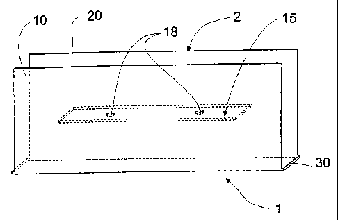
An insulating cover (1) is described, which is applicable to the statoric bars
of large size electric machines. The
objective of the present invention is to provide an insulating cover (1) that
dispenses the use of resin for its fixation and enabling
the checking of the conservation state of the end portions of the winding
along the electric machine working life. This objective is
achieved by means of an insulating cover for statoric bars of electric
machines, the cover (1) comprising first (10) and second (20)
faces positioned substantially parallel to each other and joined by at least
one joining element (15) located in a substantially central
portion of the faces (10) and (20), the element (15) being provided with at
least one fixing means (17) to fix the insulation cover (1)
to an end portion (29) of the winding of the electric machine.


French Abstract

L'invention concerne un couvercle isolant (1) s'appliquant sur des barres de stator de machines électriques de grandes dimensions. L'invention a notamment pour objectif de supprimer, grâce à ce couvercle (1), l'utilisation de résine pour la fixation de celui-ci et de permettre la vérification de l'état de conservation des portions d'extrémité de l'enroulement tout au long de la durée de vie de la machine électrique. Cet objectif est atteint au moyen dudit couvercle isolant (1) les barres de stator de machines électriques, lequel comprend une première (10) et une seconde (20) face, placées de façon sensiblement parallèles l'une à l'autre et assemblées par un élément d'assemblage (15) monté dans une portion sensiblement centrale desdites faces (1à et 20), cet élément d'assemblage (15) étant pourvu d'au moins un dispositif de fixation (17) servant à fixer le couvercle isolant (1) sur une portion d'extrémité (29) de l'enroulement de la machine électrique.

Claims

Note: Claims are shown in the official language in which they were submitted.


-5-
CLAIMS
1. An insulating cover (1), characterized in that it comprises a first face
(10) and a second
face (20), positioned substantially parallel to each other and joined by at
least one joining
element (15) located in a substantially central portion of the faces (10) and
(20), the element
(15) being provided with at least one fixing means (17) to fix the insulating
cover (1) to an
end portion (29) of an electric machine winding.
2. A cover according to claim 1, characterized in that the joining element
(15) is positioned
orthogonally with respect to the plane of the faces (10) and (20).
3. A cover according to claim 1 or 2, characterized in that a region is
defined between the
faces (10) and (20) and the joining element (15) in order to receive the end
portion (29) of the
electric machine winding.
4. A cover according to claim 1, 2, or 3, characterized in that the fixing
means (17) is a bore
(18) provided in the joining element (15), and that its fixation to the end
portion (29) of the
electric machine winding is carried out by at least one fixing element (19)
that passes through
the bore (18).
5. A cover according to claim 4, characterized in that the fixing means is a
screw (19).
6. A cover according to claim 1, 2, 3, 4, or 5,characterized in that the faces
(10) and (20) and
the joining element (15) are substantially planar.
7. A cover according to claim 6, characterized in that the faces (10) and (20)
and the joining
element (15) are substantially rectangular.
8. A cover according to claim 1, 2, 3, 4, 5, 6, or 7, characterized in that at
least one end
portion of each of the faces (10) and (20) is joined by a guide edge (30).
9. A cover according to claim 8, characterized in that the guide edge (30) is
engaged in the
end portion (29) of the electric machine winding.

-6-
10. A cover according to claim 1, 2, 3, 4, 5, 6, 7, 8, or 9, characterized in
that it is
manufactured from molded glass fiber.
11. An electric machine comprising statoric bars having an insulating cover as
claimed in any
one of claims 1 to 10.
12. A machine according to claim 11, characterized in that the end portion
(29) of the electric
machine winding is enveloped by the insulating cover (1).
13. A machine according to claim 12, characterized in that the end portion
(29) is present in
the region defined between the faces (10) and (20) and the joining element
(15) of the
insulating cover (1).

Description

Note: Descriptions are shown in the official language in which they were submitted.


CA 02398384 2006-12-22
AN INSULATING COVER AND AN ELECTRIC MACHINE
The present invention relates to an electric insulating cover, particularly
applicable to statoric bars of large-size electric machines such as
hydrogenerators.
An electric machine is also foreseen, provided with the insulating cover,
object
of the present invention.
The large-size electric machines are basically constituted of a rotor and a
stator, wherein such elements have windings which are mostly formed by bars
welded
to each other, in order to substitute the windings of small-size electric
machines that
utilize wires to construct said elements.
In particular, the statoric bars are connected to each other, forming the
imbricated or undulated windings, depending exclusively on the project
utilized for
their manufacture. Said junctions are made by welding to guarantee the circuit
conductivity, being posteriorly isolated due to the fact that their outer
portions are
exposed at machine ends.
Description of the related art
Nowadays, the insulation of such outer portions is made by placing insulating
covers, which are fixed with resins to the bar terminals. Said covers are
substantially
in a flat-parallelepiped-shaped, having one of its smaller faces opened to
engage at the
outer portions of the statoric bars, so that they can be posteriorly filled
with resin in
order to fix the cover to the bars.
However, the use of said covers presents a number of drawbacks, which raises
the time and the costs of manufacture and maintenance of electric machines
known at
present.
Among the drawbacks of the actual insulating covers, it can be detached due to
the low heat transmission, which is a significant problem because a more
heated
region arises, due to the circulation of the current during normal functioning
of the
machines and to the fact that the solder is located at the winding bar
terminals, making
the heat transmission difficult with the use of the present-day covers, since
there is no
direct ventilation on the contact region.
As a result of the use of resin in covers filling, the location becomes quite

CA 02398384 2002-07-25
WO 01/56135 PCT/BROO/00087
-2-
dirty, requiring a careful cleaning after completion of the work, which
results in a
quite long installation time. In addition, the mounting of the covers on the
upper
portion of the motor becomes difficult, because in this situation, the resin
which is still
liquid inside the insulating cover, flows along the winding bars right after
the latter
have been mounted.
In view of the use of resin, there is the obligation of the use of an
additional
Individual Protection Equipment (IPE).
Furthermore, due to the use of the actual covers, there is no possibility of
making a
direct inspection on the winding bar terminals along the working life of the
machines, because
these terminals are enveloped by resin.
Objective and brief description of the invention
The objective of the present invention is to provide an insulating cover that
dispenses the use of resin for its fixation, having a high heat transmission
by direct
ventilation of the end portions of the winding, being easy to be mounted,
maintenance and replacement dispensing the use of protection equipment, and
further enabling the checking of the conservation state of the winding end
portions
during the electric machine working life.
This objective is achieved by means of an insulating cover, particularly an
insulating cover of statoric bars of electric machines, the cover comprising
first and
second faces, positioned substantially parallel to each other and being joined
by at
least one joining element located in a substantially central portion of the
faces, and
the element being provided with at least one fixing means to fix the
insulating cover
to an outer portion of the electric machine winding.
Another objective of the present invention is to provide an electric machine
provided with an insulation cover that dispenses the use of resin for its
fixation,
enabling an easy mounting, the maintenance and replacement dispensing the use
of
protection equipment and further enabling the checking of the conservation
state of
the end portions of the winding during the electric machine working life.
This objective is achieved by means of an electric machine having an
insulation cover
on the outer portion of the statoric bars, the insulating cover having first
and second faces
positioned substantially parallel to each other and being joined by at least
one joining element
located in a substantially central portion of the faces, said element being
provided with at
least one fixing means to fix the insulator to said end portion.

CA 02398384 2002-07-25
WO 01/56135 PCT/BROO/00087
-3-
Brief description of the drawings
The present invention will now be described in greater detail with reference
to
an embodiment represented in the drawings.
- Figure 1 shows a top view of the insulating cover of the present invention;
- Figure 2 shows a side view of the insulating cover of figure 1;
- Figure 3 shows a perspective side view of the insulating cover of figures 1
and 2; and
- Figure 4 is a side view of the insulating cover illustrated in the above
figures,
showing, in partial cross-section, the mounting thereof on an end portion of
an
electric machine winding.
Detailed description of the figures
As can be seen from figures 1, 2, 3, or 4, the insulating cover 1, object of
the
present invention, is formed by a body 2 that will be engaged on an end
portion 29 of
an electric machine winding (not shown).
The body 2 comprises a first face 10 and a second face 20, both substantially
rectangular and planar in shape, positioned parallel to each other and being
joined in
a substantially central portion by means of a joining element 15, which is
defined in
an orthogonal plane with respect to the planes of the faces 10 and 20, which
are also
rectangular and planar in shape.
As can be seen from figure 3, in order to enable the faces 10 and 20 to have
good mechanical stability and not bend around the element 15, at least one of
their
end portions is joined by a guide edge 30. Preferably, a pair of guide edges
30 is
used at opposed end parts of the body 2.
The joining element 15 is provided with at least one fixing means 17 to fix
the
insulating cover I to the end portion 29 of the electric machine winding. The
fixing
means 17 should preferably be a bore 18, and more preferably a pair of bores,
so
that the insulating cover 1 can be fixed to the end portion 29 by means of a
screw
19. Evidently the fixation of the joining element 15 may vary, and other
fixing means
17 may be used, different from a screw 19. The joining element 15 may also be
made in different ways, such as, for instance, two rectangular stretches
positioned
side by side, offering the same possibility of fixing the insulating cover 1
to the end
portion 29. A single screw 19 can also be used at a central portion of the
joining

CA 02398384 2002-07-25
WO 01/56135 PCT/BROO/00087
-4-
element 15. The fixation of the insulating cover 1 may also be carried out by
engaging the end portion 29, in which case it is necessary to foresee the
exact
dimensions in order to guarantee an adequate fixation.
As can be seen from figure 4, the end portion 29 of the electric machine
winding will be introduced into the region defined between the faces 10 and
20, the
joining element 15 and the guide edges 30. Then the insulating cover 1 will be
fixed
by means of the screws 19, which pass through the bores 18. In this
embodiment,
there should be provided threaded bores 16 in the end portion 29 for threading
the
screws 19.
The dimensions of the insulating cover 1 should be adequate for the
engagement with the end portion 29 and to fit without clearance. The
insulating
cover 1 is preferably manufactured from a single piece, preferably molded from
glass
fiber. This fiber may be replaced for another material that meets the same
requirements of mechanical and electric insulation characteristics of the
preferred
material, and having a high dielectric rigidity with high electric resistance
in
transverse and longitudinal direction, and further withstanding at least
temperatures
of 1550 C, so as to meet at least class F.
The present invention provides, as one of the main advantages in comparison
with the insulating covers known from the prior art, a better heat
transmission
between the end portions 29 and the environment, generating lesser losses in
the
machine and better effectiveness, reduction in the utilization of resin during
the
mounting of the large-size electric machines, decreasing the dirt in the work
place
and eliminating the use of individual protection equipment (IPE) during the
mounting
of the insulating covers 1, reduction of the installation time of the
insulating covers 1
and, in addition, permiting a direct inspection of the end portions 29 of the
machines,
which, enables one, during the standstills for maintenance, to check the
condition of
the solders and of the terminals after periods of functioning, besides
significantly
reducing the costs of installation and maintenance of the insulating cover 1,
as well
as of the electric machine provided with this insulating cover 1.
A preferred embodiment having been described, it should be understood that
the scope of the present invention embraces other possible variants, being
limited
only by the contents of the accompanying claims, including the possible
equivalents.

Representative Drawing
A single figure which represents the drawing illustrating the invention.
Administrative Status

2024-08-01:As part of the Next Generation Patents (NGP) transition, the Canadian Patents Database (CPD) now contains a more detailed Event History, which replicates the Event Log of our new back-office solution.

Please note that "Inactive:" events refers to events no longer in use in our new back-office solution.

For a clearer understanding of the status of the application/patent presented on this page, the site Disclaimer , as well as the definitions for Patent , Event History , Maintenance Fee  and Payment History  should be consulted.

Event History

Description Date
Inactive: Expired (new Act pat) 2020-08-04
Common Representative Appointed 2019-10-30
Letter Sent 2009-06-16
Inactive: Single transfer 2009-04-30
Grant by Issuance 2008-10-28
Inactive: Cover page published 2008-10-27
Pre-grant 2008-07-30
Inactive: Final fee received 2008-07-30
Notice of Allowance is Issued 2008-01-31
Letter Sent 2008-01-31
Notice of Allowance is Issued 2008-01-31
Inactive: Approved for allowance (AFA) 2007-12-31
Amendment Received - Voluntary Amendment 2007-10-25
Inactive: S.30(2) Rules - Examiner requisition 2007-05-14
Amendment Received - Voluntary Amendment 2006-12-22
Inactive: S.30(2) Rules - Examiner requisition 2006-06-29
Letter Sent 2004-02-05
Request for Examination Requirements Determined Compliant 2003-12-29
All Requirements for Examination Determined Compliant 2003-12-29
Request for Examination Received 2003-12-29
Letter Sent 2003-02-25
Amendment Received - Voluntary Amendment 2003-01-13
Inactive: Single transfer 2003-01-13
Inactive: Courtesy letter - Evidence 2002-12-17
Inactive: Cover page published 2002-12-13
Inactive: Notice - National entry - No RFE 2002-12-11
Application Received - PCT 2002-09-25
National Entry Requirements Determined Compliant 2002-07-25
Application Published (Open to Public Inspection) 2001-08-02

Abandonment History

There is no abandonment history.

Maintenance Fee

The last payment was received on 2008-07-30

Note : If the full payment has not been received on or before the date indicated, a further fee may be required which may be one of the following

  • the reinstatement fee;
  • the late payment fee; or
  • additional fee to reverse deemed expiry.

Patent fees are adjusted on the 1st of January every year. The amounts above are the current amounts if received by December 31 of the current year.
Please refer to the CIPO Patent Fees web page to see all current fee amounts.

Owners on Record

Note: Records showing the ownership history in alphabetical order.

Current Owners on Record
VOITH SIEMENS HYDRO POWER GENERATION LTDA.
Past Owners on Record
ERNESTO LOCATTO MAZOLLA
THOMAS HILDINGER
Past Owners that do not appear in the "Owners on Record" listing will appear in other documentation within the application.
Documents

To view selected files, please enter reCAPTCHA code :


To view images, click a link in the Document Description column. To download the documents, select one or more checkboxes in the first column and then click the "Download Selected in PDF format (Zip Archive)" or the "Download Selected as Single PDF" button.

List of published and non-published patent-specific documents on the CPD .

If you have any difficulty accessing content, you can call the Client Service Centre at 1-866-997-1936 or send them an e-mail at CIPO Client Service Centre.


Document
Description 
Date
(yyyy-mm-dd) 
Number of pages   Size of Image (KB) 
Representative drawing 2002-07-24 1 7
Drawings 2003-01-12 2 58
Claims 2002-07-24 2 65
Abstract 2002-07-24 1 50
Drawings 2002-07-24 2 105
Description 2002-07-24 4 213
Description 2006-12-21 4 212
Claims 2006-12-21 2 52
Claims 2007-10-24 2 51
Representative drawing 2008-10-08 1 8
Notice of National Entry 2002-12-10 1 189
Courtesy - Certificate of registration (related document(s)) 2003-02-24 1 130
Acknowledgement of Request for Examination 2004-02-04 1 174
Commissioner's Notice - Application Found Allowable 2008-01-30 1 164
Courtesy - Certificate of registration (related document(s)) 2009-06-15 1 102
PCT 2002-07-24 3 87
Correspondence 2002-12-10 1 24
PCT 2002-07-25 6 184
Correspondence 2008-07-29 2 58