Note: Descriptions are shown in the official language in which they were submitted.
14219-OOSUS 1/P2000,001 SUSN
Description
CA 02399303 2002-08-06
Surface Wave Filter Comprising Reactance Elements
Surface acoustic wave (SAW) filters are used predominantly in GSM mobile
telephones. SAW filters are operated single-ended on an input side and
balanced on an
output side. Single-ended means that a signal is applied to only one of two
connectors,
while the other connector is grounded. This method of connection is also
referred to as
asymmetric. An input or output of a SAW filter that is operated in a balanced
mode, on
the other hand, has two connectors whose signals are ideally phase-shifted by
180°
relative to one another. This means that a signal that is equal in magnitude
can be
obtained at both connectors, and that the signal differs merely in its prefix.
Such
symmetric/asymrnetric operation is also referred to as a BALUN function.
For more modern mobile radio systems, such as EDGE, UMTS and CDMA, the
market is increasingly demanding SAW filters that can be operated in balanced
mode on
both sides. Such filters are already being installed in numerous established
mobile radio
systems under AMPS, PCS, and PDC 1.5.
Another critical factor for the mode of operation of a SAW filter is the
filter's
impedance. Until recently, a filter impedance of 50 ohm on the input side and
the output
-1-
14219-005US 1/P2000,001 SUSN
CA 02399303 2002-08-06
side was consistently being demanded and offered, while now, higher impedance
values in
the range of 100 to 400 ohm are increasingly required for balanced-balanced
filters.
A SAW HF (high frequency) filter must also satisfy stringent requirements with
regard to selection and insertion attenuation, particularly in the realm of
mobile
communication. These requirements can only be met with special, novel filter
structures.
Known filters that can be operated in balanced mode on both sides are known,
for
example, from EP-A-0 605 884. These filters are implemented using longitudinal
mode
resonator filters (= dual mode SAW = DMS filters) on lithium niobate or
lithium tantalite.
In these filters, an odd number of interdigital transformers is disposed
between two
reflectors for each track. A balanced-balanced filter is structured, for
example, as a two-
track filter, in which two tracks with three transformers are respectively
switched in
cascade via the center transfonr~er. The two outer transformers of a track are
respectively
connected to the input or output, and demonstrate a phase inversion, which
permits
symmetric operation at each input or output. Such a filter possesses the same
impedance
on the input and the output sides.
It is the object of the present invention to provide filters that can be
operated in
balanced mode on both sides, and that demonstrate a high level of selection
and a low
insertion attenuation.
-2-
14219-OOSU S 1 /P2000,001 SUSN
CA 02399303 2002-08-06
According to the invention, this object is accomplished by a surface acoustic
wave
filter according to claim 1. Advantageous further developments of the
invention ensue
from the dependent claims.
The invention proposes, for the first time, to structure an HF filter that can
be
operated in balanced mode on both sides with reactance elements on a SAW
basis. A
reactance element on a SAW basis can be embodied as a SAW resonator. However,
the
general definition of a reactance element is that it does not act as a filter
in and of itself,
but rather only by way of its impedance, which can therefore also be replaced
by any
1o desired impedance element. The filter according to the invention is
embodied to be
completely electrically symmetric. 1t has at least one four-pole reactance
series element,
with two poles (= connectors) forming the symmetric input and output,
respectively. A
four-pole reactance series element can be formed by two individual,
geometrically
identical two-pole reactance elements, or by a single (four-pole) reactance
element with
four connectors (poles). The term reactance series element is understood to
mean a SAW
reactance element that has at least one interdigital transformer, one of whose
current bars
is connected to the input side, while its other current bar is connected to
the output side,
thereby producing a serial connection (= path) between the input side and the
output side,
in which the reactance series element is embedded.
A four-pole reactance series element according to the invention represents a
basic
structure for a rudimentary SAW HF filter that accomplishes the stated object
in a simple
-3-
14219-OOSUS 1/P2000,001 SUSN
CA 02399303 2002-08-06
manner. Previous reactance filters have an asymmetric structure and possess
only one
signal-conducting connector on both sides, in other words, a single-ended
connector,
while the other connector is grounded. This type of known reactance filter
therefore
possesses only a serial path that connects the two signal-conducting
connectors with one
another on the input and output sides. The connection to ground is made via
resonators,
i.e., reactance elements switched in parallel to this. The entire arrangement
of known
reactance filters is therefore both electrically and geometrically asymmetric.
In the simplest embodiment, two resonators are provided, which together form a
reactance series element. One connector of each of the resonators is connected
to the
input side; the other is connected to the output side via the other current
bar. The
resonators are not coupled acoustically.
In a further embodiment of the invention, the two serial paths that each have
a
reactance element, i.e., a resonator, can be symmetricly connected to one
another via at
least one parallel branch, thereby producing a high-quality HF filter. In the
simplest case,
this can be a SAW resonator switched in parallel.
1t is also possible, however, to connect the inputs or outputs of the four-
pole
reactance series element to the symmetric input of a DMS filter that is
symmetric on both
sides. The outputs of the DMS filter then represent the output and input,
respectively, of a
high-quality filter in accordance with the invention.
-4-
CA 02399303 2002-08-06
14219-OOSUS 1/P2000,OO15USN
In a further embodiment of the invention, a parallel branch is also provided
between the two serial paths, in which branch two reactance elements, i.e.,
resonators,
switched in series are disposed, the elements not being acoustically coupled.
A resonator
having a current bar that has been divided into two axially symmetric parts
can also be
provided as the parallel reactance element; the two parts are each connected
to the two
connectors of the interdigital transformer. The opposite current bar of the
interdigital
transformer divided in this way represents a virtual ground point that can
also be
connected to a ground connector, if necessary.
to
A single four-pole reactance series element is also obtained if the
interdigital
transformer of a surface acoustic wave resonator is symmetricly divided into
two partial
transformers having two connectors each. On both sides of the acoustic track
of the
resonator, symmetric inputs and outputs are then formed, which represent the
inputs and
15 outputs of a basic structure of an HF filter that is fully functional with
further symmetric
SAW components.
In a further embodiment of the invention, the four-pole reactance series
element
can be switched symmetricly with other reactance elements or also in cascade
with other
2o DMS filters. Thus, a DMS filter switched in cascade with the reactance
series element
can be arranged in cascade with another symmetric DMS filter. It is also
possible to
connect two symmetric DMS filters to one another via the four-pole reactance
series
-5-
CA 02399303 2002-08-06
14219-OOSUS 1 /P2000,001 SUSN
element that is switched between them. Each of the DMS filters can again be
cascaded; in
other words, it can have several acoustic tracks switched in cascade.
In another embodiment of the invention, two four-pole reactance elements are
connected to one another crosswise, in the form of a bridge circuit. The two
connectors of
the symmetric input of the first four-pole reactance element are connected to
one
connector of the input and the output of the second four-pole reactance
element,
respectively. The hwo connectors of the output of the first reactance element
are
respectively connected to the other connector of the input and the output of
the second
to reactance element. This is a variation of the invention that does not have
a geometrically
symmetric arrangement, but merely an electrically symmetric arrangement.
A reactance filter according to the invention can also include a DMS track or
a
resonator in which two surface acoustic wave structures that are disposed
adjacent to one
15 another and are selected independently of one another from an interdigital
transformer and
a reflector are phase-shifted relative to one another. The transition between
the two
phase-shifted surface acoustic wave structures is formed by a continuously
varied finger
period and continuously varied finger distances, or only by a continuously
varied finger
period. The finger period exhibits a minimum in the region of the transition
and
20 continuously decreasing from both sides. This avoids leakage losses in the
HF filter.
14219-OOSU S 1 /P2000,001 SUSN
CA 02399303 2002-08-06
In a further embodiment of the invention, individual or groups of interdigital
transformers of reactance elements, or DMS filters or DMS tracks switched with
them,
can be weighted in order to adapt various parameters of the entire filter. For
example, the
bandwidth of the filter can be varied in this way, the impedance of the filter
can be
changed, or the selection can be increased. Such weighting can be performed as
omission
weighting or overlap weighting. Other examples of weighted interdigital
transformers
that can all be used in filters according to the invention can be found, for
example, in DE-
A-19724259 (= 97P1705), which is hereby incorporated by reference in its
entirety.
1t is also possible, however, to implement cascade weighting in an
interdigital
transformer. For this purpose, part of the interdigital transformer is
replaced by two or
more partial transformers switched in series, each having a reduced track
width. Serial
switching of the partial transformers can be achieved by incorporating an
additional
current bar into a conventional interdigital transformer. It is also possible
that an internal
current bar does not extend over the entire length of the interdigital
transformer. The
result is an interdigital transformer that is divided into several partial
transformers
switched in parallel, with one of these partial transformers being divided in
turn into two
or more partial transformers switched in series. In this way, the impedance of
the
interdigital transformer, and therefore that of the input or output or the
reactance element
or the filter, can be increased in a simple manner.
_7_
14219-005US 1/P2000,0015U SN
CA 02399303 2002-08-06
Preferably, a filter according to the invention is constructed on a single
substrate,
with lithium tantalate and lithium niobate being the preferred materials.
Electrode structures comprising aluminum, an aluminum/copper alloy, aluminum
and copper layers, an aluminum/magnesium alloy, or aluminum and magnesium
layers are
suitable for the use as metal on these substrate materials. These materials
are
distinguished by good adhesion to the substrate material, for example. A SAW
HF filter
according to the invention is also highly geometrically symmetric, with the
exception of
the bridge circuit, when implemented on the piezoelectric substrate.
Consequently, the
to electrical connectors (poles) are also arranged symmetricly on the
substrate. Ifthe filter
according to the invention is mounted to a base plate using flip-chip
technology, in which
the substrate is connected to metal that faces the base plate by way of solder
beads or
bumps, this produces filters that have particularly compact external
dimensions.
15 The invention will be explained in greater detail below by way of exemplary
embodiments and the associated 14 figures.
Figure 1 shows a four-pole reactance element comprising two reactance
elements;
2o Figure 2 shows a reactance series element configured as a four-pole
reactance
element;
_g_
'- CA 02399303 2002-08-06
14219-005US 1/P2000,001 SUSN
Figure 3 shows two symmetric resonators switched in series in the parallel
branch;
Figure 4 shows a symmetric parallel branch with a reactance element;
Figure 5 shows a symmetric DMS filter structure;
Figure 6 shows a reactance element in the symmetric parallel branch;
Figure 7 shows a symmetric reactance series element in cascade with a
symmetric
DMS filter;
Figure 8 shows a symmetric DMS filter in cascade with a symmetric reactance
series element;
Figure 9 shows a symmetric reactance element switched between two symmetric
DMS filters;
Figure 10 shows two serial reactance elements with a reactance element
switched
in parallel, so that the elements form a symmetric reactance filter;
Figure l 1 shows a four-pole symmetric reactance series element, with a two-
pole
reactance element being switched in parallel thereto, forming a symmetric
reactance filter;
-9-
I 4219-005US 1/P2000,001 SUSN
CA 02399303 2002-08-06
Figure 12 shows a bridge circuit comprising two four-pole reactance series
elements;
Figure 13 shows a transmission curve of a filter according to the invention;
and
Figure 14 shows an interdigital transformer, partly divided into half tracks,
for a
reactance element having increased impedance.
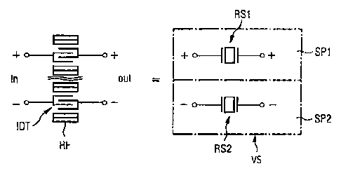
Figure 1 illustrates a simple embodiment of the invention, in which the four-
pole
reactance series element is formed by two geometrically identical reactance
elements RS
configured as resonators. Two two-pole reactance elements RS1, RS2 each have a
connector (pole), which connectors together form the input IN, while the two
other
connectors form the output OUT. Each reactance element comprises an
interdigital
transformer IDT, which is disposed between two reflectors RF. The first
reactance
element RS1 forms the first serial path SP1 and the second reactance element
RS2 forms
the second serial path SP2, as shown in simplified form in the right part of
Figure 1. The
two reactance elements RS are not acoustically coupled to each other, as
illustrated in the
left part of the drawing by the double wave line. Figure 2 shows a four-pole
reactance
series element that is embodied as a reactance element (resonator) having four
connectors.
In this resonator, the central interdigital transformer is synmetricly divided
in the center
into a first partial transformer Tl and a second partial transformer T2, each
of which has
-10-
14219-OOSUS 1/P2000,001 SUSN
CA 02399303 2002-08-06
two connectors. In this case, two connectors located on one side are combined
to form the
input IN or the output OUT, respectively. Such a four-pole reactance element
represents a
rudimentary SAW filter. Because of the reciprocity of SAW components, it is
clear for
this and all other filters according to the invention that they can also be
operated in the
opposite direction, that is, in a mode of operation in which the inputs and
outputs IN, OUT
are reversed. This also holds true for the arrangement of the partial
structures described
below, which can be switched in cascade with such a reactance series element.
Figure 3 shows a parallel branch PA, which can be switched between the IN and
OUT connectors on the input or output side of the reactance series element.
Two
reactance elements RP are switched in series in the parallel branch. A virtual
ground
point G exists between the two reactance elements RP, which demonstrates a
constant
electrical potential because of its symmetric central position between the
serial paths, and
can optionally also be connected to ground.
Figure 4 shows a reactance element with a different structure, which is
likewise
arranged in a parallel branch and can be switched between the two connectors
of the input
or the output of a reactance series element. This reactance element has an
interdigital
transformer that is disposed between two reflectors and has a current bar that
is
s~~rnmetricly divided into two partial bars TS1, TS2 (shown on the right in
the figure). As
a result, the interdigital transformer is divided into two partial
transformers that are
-11-
- CA 02399303 2002-08-06
14219-OOSUS 1/P2000,001 SUSN
switched in series and together represent a reactance element for the parallel
branch, and
can be connected to one of the reactance series elements shown in Figures 1 or
2.
Figure 5 shows a known DMS filter, which can function on its own, and has
symmetric connectors on the input and output sides. The center interdigital
transformer of
the three interdigital transformers is provided with two IN connectors on one
side of the
acoustic track through the symmetric division of one current bar. These
connectors form
the symmetric input 1N. The two outer interdigital transformers are connected
to the
output OUT. Such a symmetric DMS filter can now be connected to the input or
the
output of a reactance series element, similar to a reactance element in the
parallel branch,
as an additional partial structure (see Figure 1 or 2), or, to state it
differently, it can be
switched in cascade with this element. It is also possible to switch a DMS
filter in
cascade with a reactance series element that has a reactance element in the
parallel branch.
Figure 6 shows another possible partial structure that can be connected to a
reactance series element according to the invention. Here, a simple SAW
resonator is
disposed in a parallel branch as a parallel reactance element RP.
Figure 7 shows a further embodiment of the invention, in which a four-pole
reactance series element VS is switched in cascade with a symmetric DMS filter
DMS
(see Figure 5, for example). The output formed via the outer interdigital
transformers of
-12-
- CA 02399303 2002-08-06
14219-OOSU S 1 /P2000,001 SUSN
the DMS filter DMS is connected to the two connectors of the input of the
reactance series
element.
Figure 8 shows a switching layout similar to that in Figure 7, but here, the
symmetric DMS filter DMS is connected to the reactance series element VS via
the two
connectors of the center interdigital transformer. Figure 9 shows a reactance
series
element VS that is switched in cascade with a respective symmetric DMS filter
DMS1,
DMS2 on both sides. In the illustrated embodiment, the DMS filters are each
connected
to the reactance series elements via the outer interdigital transformers. It
is also possible,
however, to create the connection between the DMS filter and the reactance
series element
via the two connectors of the center interdigital transformer of the DMS
filters.
Figure 10 shows a filter according to the invention, in which two serial paths
are
provided, with a two-pole reactance element RS1, RS2 (resonator) being
disposed in each
path. The two serial paths are bridged with a further two-pole reactance
series element,
i.e., with a two-pole resonator, which is disposed in the parallel branch. In
this instance,
the resonator (RP) in the parallel branch is unbalanced in frequency relative
to the
resonators (RS1, RS2) in the serial paths, so the resonance frequencies of the
resonators
(RSl, RS2) in the serial paths are greater than or equal to the anti-resonance
frequency of
the resonator (RP) in the parallel branch (PA).
-13-
CA 02399303 2002-08-06
14219-005US 1/P2000,001 SUSN
Figure 11 shows a reactance series element VS in which the two connectors of
the
output OUT are switched in parallel with a two-pole reactance element RP. This
reactance element of the parallel branch corresponds to the reactance element
shown in
Figure 4; namely, it has a divided current bar at the interdigital
transformer. In an
advantageous embodiment of this filter, the electrical connectors for the
output OUT are
connected to the reflectors of the reactance element in the parallel branch,
and these are
connected to the outputs of the reactance series element VS. In this manner,
the
electrically inactive reflectors, which likewise comprise metallic structures,
can be used as
tracks. This eliminates the need for additional tracks on the surface of the
chip on which
the filter is constructed.
Figure 12 shows a further filter according to the invention, in which two four-
pole
reactance series elements VSl, VS2 are switched crosswise to form a bridge.
The
resonators A and B of the two reactance series elements are unbalanced
relative to each
other in terms of frequency, which can be adjusted by means of a different
finger period or
a different distance between the interdigital transformer and the reflectors
of the
resonators, for example.
Figure 13 shows a transmission curve of a filter according to the invention,
which
was determined using a filter embodied according to Figure 7, for example. The
filter
demonstrates a high level of selection of more than 20 dB, and a low insertion
attenuation
of a maximum of 3 dB over the entire transmission range. Therefore, this
filter is
-14-
- ~ CA 02399303 2002-08-06
14219-OOSUS 1 /P2000,001 SUSN
particularly well suited for use in mobile radio systems, since it meets the
strict
specifications required for this purpose. This also holds true for all of the
other filters of
the invention that are described in the exemplary embodiments.
Figure 14 shows a cascade-weighted interdigital transformer that is known per
se,
and can be used in the reactance elements of filters according to the
invention, or in DMS
filter switched in cascade to form reactance series elements; the transformer
increases the
impedance of the corresponding filter or reactance element. It has an
additional center
current bar ZS, at least in part, which divides the transformer into two
partial transformers
to switched in series. The figure shows an interdigital transformer of this
type, which can be
divided into three partial transformers TW1, TW2, and TW3 switched in parallel
with one
another, with the center partial transformer TW3 in turn comprising two
partial
transformers switched in series via the additional current bar ZS. This
interdigital
transformer has an increased impedance as compared with a normal interdigital
transformer.
The variations of the invention described in the exemplary embodiments
represent
only a few of the solutions that are possible by combining the individual
elements
described above, and which can be realized. This invention is therefore not
limited to the
2o structures shown, and ensues in a general form from claim 1.
-15-