Note: Descriptions are shown in the official language in which they were submitted.
CA 02399782 2002-08-26
ELECTRODE FOR SOLID POLYMER FUEL CELLS
BACKGROUND OF THE INVENTION
Field of the Invention
The present invention relates to an electrode for solid polymer fuel cells,
and more particularly relates to a technology for improving catalyst function.
Description of the Related Art
A solid polymer fuel cell is composed by laminating separators at both
sides of a tabular membrane electrode assembly (MEA). The membrane
electrode assembly is generally a laminated body having a polymer electrolyte
membrane placed between a positive side electrode catalyst layer and a
negative
side electrode catalyst layer, and having a gas diffusion layer laminated at
the
outside of each electrode catalyst layer. According to such fuel cell, for
example, by passing hydrogen gas in a gas passage of the separator disposed at
the negative electrode side, and by passing an oxidizing gas in a gas passage
of
the separator disposed at the positive electrode side, an electrochemical
reaction
occurs, and an electric current is generated.
During operation of the fuel cell, the gas diffusion layer transmits
electrons generated by electrochemical reaction between the electrode catalyst
layer and the separator, and diffuses the fuel gas and oxidizing gas at the
same
time. The negative side electrode catalyst layer induces a chemical reaction
in
the fuel gas to generate protons (H+) and electrons, and the positive side
electrode catalyst layer produces water from oxygen, protons and electrons,
while the electrolyte membrane transmits the protons by ion conduction.
1
CA 02399782 2002-08-26
Elet;tric power is thereby obtained through the positive and negative
electrode
catalyst layers. Herein, the electrode catalyst layer is composed of a
catalyst
paste having mixed therein carbon particles carrying catalyst particles made
of a
platinum group metal such as Pt on the surface and an electrolyte comprising
ion
conductive polymer, and the electrochemical reaction is believed to take place
in
a three-phase interface in which catalyst, electrolyte and gas coexist.
In the catalyst paste obtained in the conventional process of mixing
carbon particles carrying catalyst particles, and electrolyte comprising ion
conductive polymer, the utilization rate of catalyst particles in the
electrochemical reaction tended to be lower. Accordingly, carbon particles
carrying catalyst particles were used in greater amount than necessary, and
since
the catalyst particles are made of expensive platinum group metals such as Pt,
as
a result, the cost was extremely disadvantageously high.
SUMMARY OF THE INVENTION
An object of the present invention is to provide an electrode for solid
polymer fuel cells capable of generating power at high output and high
efficiency without increasing the amount of catalyst used.
The present inventors intensively researched in order to achieve the
object and noted the X-ray diffraction measured value of the catalyst
substance
of the electrode surface as a parameter, and discovered a specific range of
measured values in which the catalyst activity is high, the consumption of the
catalyst substance is less than previously, and the electrode generating
electric
power at higher efficiency is obtained. The present invention is based on this
2
CA 02399782 2002-08-26
finding, and discloses an electrode for solid polymer fuel cells comprising a
catalyst substance, electroconductive particles, and an ion conductive
polymer,
in which the ratio I (111)/I (200) of peak intensity I (111) of (111) plane
and
peak intensity I (200) of (200) plane is 1.7 or less when the X-ray
diffraction of
catalyst substance of the electrode surface is measured.
The present invention can be demonstrated by measurement of the
absolute value of Tafel slope. As shown in Fig. 1, the Tafel slope is a
declining
inclination of I-V (current density-voltage) curve in the low current region,
and
when an I-V curve is plotted on the logarithmic scale of current density, a
straight line is formed in the low current region. When the inclination of the
straight line in this linear region is small, the catalyst activity is high,
or when
the inclination is large, the catalyst activity is small. In the embodiments
given
below, the calculation range estimates the inclination in the range of 0.003
to 0.1
A/cm2, and it is known that the inclination is smaller than in the prior art
when
the ratio of the peak intensity is 1.7 or less.
As the catalyst substance to be used in the present invention, a platinum
group metal, in particular, platinum, is preferred. By feeding the catalyst
substance both before and after the electrode catalyst layer forming process,
the
electrode of the present invention can be manufactured favorably. In such a
case, therefore, the catalyst substance is composed of catalyst substance A to
be
supplied before forming the electrode catalyst layer, and catalyst substance B
to
be supplied after forming the electrode catalyst layer.
In the case in which the catalyst substance A is supplied before forming
the electrode catalyst layer, after mixing a catalyst precursor substance,
3
CA 02399782 2002-08-26
eleCtroconductive particles and ion conductive polymer, the catalyst precursor
substance may be chemically reduced, or in the case in which the catalyst
substance B is supplied after forming the electrode catalyst layer, a catalyst
substance dispersed in an aqueous solution may be sprayed and applied on the
surface of the electrode catalyst layer at the side contacting with the
electrolyte
membrane.
Furthermore, the inventors intensively researched the electric charge
amount of the catalyst substance measured in a both-side humidifying method
and a one-side humidifying method as the parameter, and discovered that
catalyst activity is high when the electric charge amount in the one-side
humidifying method is 15% or more of the electric charge amount in the both-
side humidifying method, and hence that the consumption of the platinum group
metal used as the catalyst substance may be reduced from the conventional
level,
thereby obtaining an electrode capable of generating electric power at higher
efficiency. Therefore, when the membrane electrode assembly for solid
polymer fuel cells is manufactured by laminating the electrode for solid
polymer
fuel cells of the present invention as an electrode catalyst layer on one side
or
both sides of the electrolyte membrane, the rate of the electric charge of
catalyst
substance existing in an ion conduction passage from the electrolyte membrane
measured by a cyclic voltametric method is preferred to be 15% or more of the
electric charge of the total catalyst substance existing in the electrode
catalyst
layer.
The above cyclic voltametric method (electrochemical surface area
measuring method of catalyst substance) is explained below. In an ordinary
4
CA 02399782 2002-08-26
cyclic voltametric method, as shown in Fig. 2A, a humidifying gas is supplied
to
both a cathode (positive electrode) 2 and an anode (negative electrode) 3 of a
membrane electrode assembly 4 in which the electrodes 2 and 3 compose
electrode catalyst layers at both sides of an electrolyte membrane 1, and an
electric charge amount is measured on the basis of the electrochemical surface
area of all catalyst substances in the electrode catalyst layer. In this case,
humidifying gas is supplied to both electrodes 2 and 3, and this is the both-
side
humidifying method, and hence water permeates in all areas in the cell, and
all
catalyst substances existing in the electrode catalyst layer are objects of
measurement.
In contrast, in the cyclic voltametric method shown in Fig. 2B, by
humidifying only from the anode 3, the electric charge amount of the catalyst
substance is measured, and hence this is the one-side humidifying method. In
this one-side humidifying method, the water supplied from the anode 3
disperses
only through the conduction passage of the ion conductor at the cathode 2
side.
Hence, in the ion conduction passage in the cathode 2, the catalyst substance
existing at the interface of the electrolyte membrane and electrode (electrode
catalyst layer) is the main object of measurement.
This aspect of the present invention can be also demonstrated by
measurement of the absolute value of Tafel slope. According to this
measurement, when the rate of the electric charge of the catalyst substance
existing in the ion conduction passage from the electrolyte membrane measured
by the cyclic voltammetric method is 15% or more of the electric charge of the
total catalyst substances existing in the electrode catalyst layer, it is
disclosed
CA 02399782 2002-08-26
that the inclination of the straight line in the linear region of the I-V
curve is
smaller than in the prior art.
BRIEF DESCRIPTION OF THE DRAWINGS
Fig. 1 is an explanatory diagram of Tafel slope;
Fig. 2A is a conceptual diagram of the both-side humidifying method in
the cyclic voltametric method, and Fig. 2B is a conceptual diagram of the one-
side humidifying method in the cyclic voltametric method;
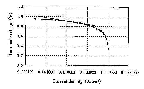
Fig. 3 is a diagram showing the relationship of the current density and
the generated voltage in Examples of the present invention;
Fig. 4 is a diagram showing the relationship of the absolute value of
Tafel slope and the peak intensity ratio I (111)/I (200) in Examples of the
present
invention;
Fig. 5 is a diagram showing the relationship of the platinum amount and
the total electric charge of catalyst substance in Examples of the present
invention;
Fig. 6 is a diagram showing the relationship of the platinum amount and
the interface electric charge of catalyst substance in Examples of the present
invention;
Fig. 7 is a diagram showing the relationship of the absolute value of
Tafel slope and the ratio of the interface electric charge to total electric
charge of
the catalyst substance in Examples of the present invention; and
Fig. 8 is a diagram showing the relationship of the current density and
the generated voltage in Examples of the present invention.
6
CA 02399782 2002-08-26
DESCRIPTION OF THE PREFERRED EMBODIMENTS
The present invention is more specifically described below by referring
to preferred embodiments.
Example 1
100 g of ion conductive polymer (trade name: Nafion SE5112, produced
by Du Pont Kabushiki Kaisha), 5 g of Ketienblack EC, and 27.4 g of 10%
[Pt(N02)2(NH3)Z~ nitric acid aqueous solution as catalyst precursor substance
were mixed, an ethanol solution was added to this mixture to reduce it, and a
catalyst paste was obtained. This catalyst paste was applied and dried on a
sheet of FEP (tetrafluoroethylene-hexafluoropropylene copolymer), and an
electrode sheet A was obtained. The platinum content in this electrode sheet A
was 0.30 mg/cm2. 1 g of platinum black (trade name: HiSPEC1000, produced
by Johnson Matthey Japan Incorporated) was dissolved in 100 g of purified
water, this platinum black solution was sprayed and applied on the electrode
sheet A by a spray method, and an electrode sheet B of Example 1 was obtained.
The platinum content in this electrode sheet B was 0.35 mg/cm2. As a result of
X-ray diffraction measurement of platinum on the surface of the electrode
sheet
B in Example 1, the ratio I (111)/I (200) of peak intensity I (111) of (111)
plane
and peak intensity I (200) of (200) plane was 1.4.
Example 2
An electrode sheet B of Example 2 was obtained in the same manner as
in Example 1 except that 46.2 g of the 10% [Pt(NOZ)Z(NH3)Z] nitric acid
aqueous
solution was used. As a result of X-ray diffraction measurement of platinum
on the surface of the electrode sheet B in Example 2, the peak intensity ratio
I
7
CA 02399782 2002-08-26
(111)/I (200) was 1.6.
Example 3
An electrode sheet B of Example 3 was obtained in the same manner as
in Example 1 except that 13.7 g of the 10% [Pt(NO2)2(NH3)Z) nitric acid
aqueous
solution was used. As a result of X-ray diffraction measurement of platinum
on the surface of the electrode sheet B in Example 3, the peak intensity ratio
I
(111)/I (200) was 1.2.
Comparative Example 1
An electrode sheet B of Comparative Example 1 was obtained in the
same manner as in Example 1 except that the catalyst paste was prepared by
mixing 100 g of ion conductive polymer (trade name: Nafion SE5112, produced
by Du Pont Kabushiki Kaisha), and 10 g of platinum carrying carbon particles
(trade name: TE10ESOE, produced by Tanaka Kikinzoku Kogyo K.K) of carbon
black and platinum at a ratio of 50: 50 by weight. As a result of X-ray
diffraction measurement of platinum on the surface of the electrode sheet B in
Comparative Example 1, the peak intensity ratio I (111)/I (200) was 1.9.
Comparative Example 2
An electrode sheet .B of Comparative Example 2 was obtained in the
same manner as in Example 1 except that 76.1 g of the 10% [Pt(N02)2(NH3)2]
nitric acid aqueous solution was used. As a result of X-ray diffraction
measurement of platinum on the surface of the electrode sheet B in Comparative
Example 2, the peak intensity ratio I (111)/I (200) was 1.8.
The electrode sheets B of Examples 1 to 3 and Comparative Examples 1
and 2 were transferred to both sides of a polymer electrolyte membrane (of
8
CA 02399782 2002-08-26
Nafion) by a decal method, and membrane electrode assemblies of Examples 1
to 3 and Comparative Examples 1 and 2 were obtained. Transfer by a decal
method is performed by peeling off the FEP sheet after thermal compression
bond of the electrode sheet on the polymer electrolyte membrane. On both
sides of the obtained membrane electrode assembly, hydrogen gas and air were
supplied to generate electric power. The temperature of both the hydrogen gas
and the air was 80~ . The utilization rate of hydrogen gas
(consumption/supply) was 50%, and the utilization rate of air was 50%. The
humidity of hydrogen gas was 50% RH, and the humidity of air was 50% RH.
In this power generation, the relationship between the current density and
voltage is shown in Fig. 3. The absolute value of the Tafel slope was
determined on the basis of the inclination of the range of the current density
0.003 to 0.1 A/cm2 in Examples 1 to 3 and Comparative Examples 1 and 2, as
described above referring to Fig. 1, and the relationship with the peak
intensity
ratio I (111)/I (200) was determined. The results are shown in Fig. 4.
As shown in Fig. 4, when the peak intensity ratio I (111)/I (200) exceeds
1.7, the absolute value of the Tafel slope rises suddenly, and this peak
intensity
ratio is within a range of 1.7 or less in Examples 1 to 3, while it exceeds a
range
of 1.7 in Comparative Examples 1 and 2. As is apparent from Fig. 3, the power
generation performance of Examples 1 to 3 is higher than that of Comparative
Examples 1 and 2, and for this reason, it was confirmed that the catalyst
activity
is high and power generation performance is superior in the range of the peak
intensity ratio I (111)/I (200) of 1.7 or less.
9
CA 02399782 2002-08-26
' Next, the present invention is more specifically described below by
referring to membrane electrode assemblies for solid polymer fuel cells in
which
the present invention is applied.
Example 4
A catalyst paste was obtained by mixing 100 g of ion conductive
polymer (trade name: Nafion SE5112, produced by Du Pont Kabushiki Kaisha),
and 10 g of platinum carrying carbon particles (trade name: TE10ESOE,
produced by Tanaka Kikinzoku Kogyo K.K) of carbon black and platinum at a
ratio of 50: 50 by weight. This catalyst paste was applied and dried on a
sheet
of FEP (tetrafluoroethylene-hexafluoropropylene copolymer), and an electrode
sheet A was obtained. The platinum content in this electrode sheet A was 0.30
mg/cm2. Then, 1 g of platinum black (trade name: HiSPEC1000, produced by
Johnson Matthey Japan Incorporated) was dissolved in 100 g of purified water,
this platinum black solution was sprayed and applied on the electrode sheet A
by
a spray method, and an electrode sheet B of Example 4 was obtained. The
platinum content in this electrode sheet B was 0.40 mg/cm2.
Example 5
An electrode sheet B of Example 5 was obtained in the same manner as
in Example 4 except that the platinum black solution was sprayed and applied
on the electrode sheet A so that the platinum content in the electrode sheet B
was 0.38 mg/cm2.
Example 6
An electrode sheet B of Example 6 was obtained in the same manner as
in Example 4 except that the platinum black solution was sprayed and applied
CA 02399782 2002-08-26
on the electrode sheet A so that the platinum content in the electrode sheet B
was 0.36 mg/cm2.
Example 7
An electrode sheet B of Example 7 was obtained in the same manner as
in Example 4 except that the platinum black solution was sprayed and applied
on the electrode sheet A so that the platinum content in the electrode sheet B
was 0.34 mg/cm2.
Example 8
An electrode sheet B of Example 8 was obtained in the same manner as
in Example 4 except that the platinum black solution was sprayed and applied
on the electrode sheet A so that the platinum content in the electrode sheet B
was 0.32 mg/cm2.
Comparative Example 3
An electrode sheet B of Comparative Example 3 was obtained in the
same manner as in Example 4 except that the platinum black solution was
sprayed and applied on the electrode sheet A so that the platinum content in
the
electrode sheet B was 0.31 mg/cm2.
Comparative Example 4
An electrode sheet B of Comparative Example 4 was obtained in the
same manner as in Example 4 except that the platinum black solution was
sprayed and applied on the electrode sheet A so that the platinum content in
the
electrode sheet B was 0.50 mg/cm2.
In the electrode sheets B of Examples 4 to 8 and Comparative Examples
3 and 4, the electric charge amount of the catalyst substance was measured by
11
CA 02399782 2002-08-26
the 'both-side humidifying method and the one-side humidifying method in the
cyclic voltametric method. The electric charge amount in the both-side
humidifying method is the electric charge amount of the total catalyst
substance,
and the electric charge amount in the one-side humidifying method is the
electric discharge amount at the interface of the catalyst substance and
electrolyte membrane. The measured values by the both-side humidifying
method are shown in Fig. 5, and the measured values by the one-side
humidifying method are shown in Fig. 6.
Furthermore, the absolute value of the Tafel slope was determined in
Examples 4 to 8 and Comparative Examples 3 and 4 on the basis of the
inclination of the current density in a range of 0.003 to 0.1 A/cm2, as
described
above referring to Fig. 1. Also in Examples 4 to 8 and Comparative Examples
3 and 4, the ratio of electric charge amount of catalyst substance in the one-
side
humidifying method to electric charge amount of catalyst substance in the both-
side humidifying method was determined, and the relationship of this ratio and
the absolute value of the Tafel slope was determined. The results are shown in
Fig. 7.
The electrode sheets B of Examples 4 to 8 and Comparative Examples 3
and 4 were transferred on both sides of a polymer electrolyte membrane (of
Nafion) by a decal method, and membrane electrode assemblies of Examples 4
to 8 and Comparative Examples 3 and 4 were obtained. Transfer by a decal
method is performed by peeling off the FEP sheet after thermal compression
bonding of the electrode sheet on the polymer electrolyte membrane. On both
sides of the obtained membrane electrode assembly, hydrogen gas and air were
12
CA 02399782 2002-08-26
supplied to generate electric power. The temperature of both hydrogen gas and
air was 80°C . The utilization rate of hydrogen gas
(consumption/supply) was
50%, and the utilization rate of air was 50%. The humidity of hydrogen gas
was 50% RH, and the humidity of air was 50% RH. In this power generation,
the relationship between the current density and voltage is shown in Fig. 8.
As shown in Fig. 5, the total electric charge amount of catalyst substance
measured in the both-side humidifying method is proportional to the platinum
coating amount. However, as shown in Fig. 6, the interface electric charge
amount of catalyst substance measured in the one-side humidifying method was
not in proportional relationship to the platinum coating amount, and dropped
significantly in Comparative Example 4 with the largest platinum coating
amount. Furthermore, as shown in Fig. 7, when the ratio of the interface
electric charge amount to the total electric charge amount exceeds 15 %, the
absolute value of the Tafel slope sharply increases, and the ratio is in a
range of
15 % or more in Examples 4 to 8, while it is under 15 % in Comparative
Examples 3 and 4. As is apparent from Fig. 8, the power generation
performance of Examples 4 to 8 is higher than in Comparative Examples 3 and 4,
and hence it was confirmed that the catalyst activity is high and the power
generation performance is superior at the ratio of 15% or more.
13