Language selection

Search

Patent 2399994 Summary

Third-party information liability

Some of the information on this Web page has been provided by external sources. The Government of Canada is not responsible for the accuracy, reliability or currency of the information supplied by external sources. Users wishing to rely upon this information should consult directly with the source of the information. Content provided by external sources is not subject to official languages, privacy and accessibility requirements.

Claims and Abstract availability

Any discrepancies in the text and image of the Claims and Abstract are due to differing posting times. Text of the Claims and Abstract are posted:

  • At the time the application is open to public inspection;
  • At the time of issue of the patent (grant).
(12) Patent Application: (11) CA 2399994
(54) English Title: RECESSED AIR CONDITIONING CONTROLS FOR A UTILITY VEHICLE
(54) French Title: COMMANDES DE CLIMATISATION ENCASTREES POUR VEHICULE UTILITAIRE
Status: Deemed Abandoned and Beyond the Period of Reinstatement - Pending Response to Notice of Disregarded Communication
Bibliographic Data
(51) International Patent Classification (IPC):
  • B60H 1/00 (2006.01)
(72) Inventors :
  • ARTHUR, JOHN RAYMOND (United States of America)
  • STRONG, RUSSELL WILLIAM (United States of America)
  • OLSON, DANIEL (United States of America)
(73) Owners :
  • DEERE & COMPANY
(71) Applicants :
  • DEERE & COMPANY (United States of America)
(74) Agent: NORTON ROSE FULBRIGHT CANADA LLP/S.E.N.C.R.L., S.R.L.
(74) Associate agent:
(45) Issued:
(22) Filed Date: 2002-08-28
(41) Open to Public Inspection: 2003-02-28
Examination requested: 2004-05-28
Availability of licence: N/A
Dedicated to the Public: N/A
(25) Language of filing: English

Patent Cooperation Treaty (PCT): No

(30) Application Priority Data:
Application No. Country/Territory Date
09/945,538 (United States of America) 2001-08-29

Abstracts

English Abstract


A steering wheel console is provided that includes a sidewall with a
recessed area. The recessed area carries air conditioning controls in a
fashion that the controls do not extend outwardly of the recessed area. By
locating the controls within the recessed area, the controls are substantially
protected from being disturbed by interference from an operator's leg during
entry and exit to/from the utility vehicle and during operation of the utility
vehicle.


Claims

Note: Claims are shown in the official language in which they were submitted.

In the claims:
1. In a utility vehicle having an operator's seat facing a steering
wheel console, the improvement comprising:
a recessed control panel formed into a first sidewall of said
steering console, said panel including controls which extend from said
recessed area to a height that is recessed from the sidewall of the
steering console.
2. The improvement according to claim 1, wherein said controls
comprise switches associated with an air conditioning system of the utility
vehicle.
3. The improvement according to claim 2, wherein said sidewall of
said steering console comprises vents for distributing air.
4. The improvement according to claim 4, wherein said steering
console defines an internal volume housing an air duct, and wherein an air
filter associated with said air conditioning system is mounted within said
internal volume and arranged to close said duct.
5. The improvement according to claim 4, wherein said steering
wheel console comprises a second sidewall opposite said first sidewall, and a
recessed area is formed in said second sidewall, said recessed area

comprising a grille for allowing air to pass through said second sidewall,
said
filter arranged behind said grille.
7

Description

Note: Descriptions are shown in the official language in which they were submitted.


CA 02399994 2002-08-28
Recessed Air Conditioning Controls For A Utility Vehicle
Technical Field of the Invention
The invention relates to utility vehicles, particularly to control panel
layouts for utility vehicles.
Background Of The Invention
A utility vehicle, such as disclosed in U.S. Patent 5,064,339 and
5,967,737 can be equipped with front-end loader buckets, and rear-mounted
io backhoe attachments. Tractors can also be equipped with other tools such
as snowblowers, lawnmower decks, tillers, etc. Generally, the more functions
a utility vehicle is equipped for, the more controls are required. in a
limited-
size operator station or cab, controls must be carefully arranged to provide
for
convenient, effective and efficient operation of the vehicle by the operator.
is Because of the relatively confined area of the operator station,
dashboard areas or control panel areas, accessible to the operator, become
scarce. Controls which are located in and around the cab footwells can be
inadvertently changed by contact with the operator's leg.
The present inventors have recognized that it would be desirable to
2o provide additional control panel areas, accessible to an operator, while
being
relatively protected from inadvertent actuation by an operator, during
operation and when climbing in and out of the utility vehicle.

CA 02399994 2002-08-28
Summary Of The Invention
The present invention provides a steering wheel console for a utility
vehicle which provides a recessed sidewall which provides a mounting
surface for control elements. The control elements, being recessed, are
substantially protected from being inadvertently actuated or disturbed by an
operator.
The invention particularly provides a recessed panel on the steering
wheel console for holding heating, ventilating and air conditioning (HVAC)
controls for the utility vehicle and a recessed panel for carrying an ignition
io switch and an air intake for the HVAC system. Furthermore, the steering
console provides a volume for housing the air filter and ducting for the
heating, ventilating and air conditioning system.
Numerous other advantages and features of the present invention will
become readily apparent from the following detailed description of the
is invention and the embodiments thereof, from the claims and from the
accompanying drawings.
Brief Description Of The Drawings
Figure 1 is an elevational view of a compact tractor incorporating the
2o steering wheel console of the present invention ;
Figure 2 is an enlarged, fragmentary left-side-perspective view of the
steering wheel console of Figure 1;
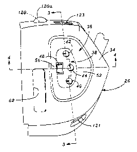
Figure 3 is a sectional view taken generally along lines 3-3 of Figure 2;

CA 02399994 2002-08-28
Figure 4 is a sectional view taken generally along lines 4-4 of Figure 2;
and
Figure 5 is an enlarged fragmentary right-side perspective view of the
steering wheel console of Figure 1.
Detailed Description Of The Preferred Embodiments
While this invention is susceptible of embodiment in many different
forms, there are shown in the drawings, and will be described herein in
detail,
specific embodiments thereof with the understanding that the present
io disclosure is to be considered as an exemplification of the principles of
the
invention and is not intended to limit the invention to the specific
embodiments illustrated.
Figure 1 is a side elevational view of a utility tractor 10 of the present
invention. The utility vehicle 10 includes a chassis or frame 11 supported on
is front wheels 12 and larger rear wheels 13. A hood 14 covers an engine
compartment. The utility vehicle 10 includes an operator's station 16 which
includes an operator's seat 20 and a steering wheel console 26. A steering
wheel 30 protrudes from the steering wheel console 26 to be located in the
vicinity of the seat 20, for operating the vehicle 10.
2o Figure 2 illustrates the steering wheel console 26 separate from the
remaining portions of the utility vehicle 10. The steering wheel console 26
includes a sidewall 34 having a dished or recessed area 36 for holding
controls 38, particularly controls for the HVAC system of the utility vehicle.
The controls can include a fan speed switch 42 which determines the volume

CA 02399994 2002-08-28
of air blown by the HVAC fan, a temperature control dial 44 which determines
the mixture of cold and warm air blown by the fan, and a routing switch 46
which determines the routing or air direction delivered by the HVAC system.
An on-off switch 48 is provided to tum on or off the air conditioning
s compressor of the vehicle.
The recessed area 36 includes a blended gentle sloping frontwall 52
and a steeper rearwall 56. The more gently sloping front wall 52 aids the
operator in reaching and manipulating the controls from the operators position
on the seat 20. The steeper rear wall 56 provides a location for label
io placement to describe control functions.
As shown in the sectional view of Figures 3 and 4, The recessed area
36 as shown in Figure 3 is recessed sufficiently that the controls 42, 44, 46,
48 are all beneath the level of the surface 34a of the sidewall 34.
Figure 5 illustrates the console 26 having an opposite sidewalt 70 and
is a centralized recessed area 72. An ignition switch 76, shown with a key 78,
is
located within the recessed area 72 fit therein. A grille 79 within the
recessed
area 72 provides openings 82 for passing air to a filter element 86 (shown in
fragmentary fashion) behind the grille 79. The filler element 86 fronts an air
inlet duct for the HVAC system. A retaining spider 88 is connected by a bolt
20 89, which retains the filter 86 behind the grille 79. The console 26
provides a
front wall 102 which has an opening 106 for passing a steering shaft 110 of
the steering wheel 30. The opening 106 allows for tilting the steering wheel
30.
4

CA 02399994 2002-08-28
As illustrated in Figures 2 and 5, delivery ducts or vents 62, 92, 112,
114, 120, 121, 122, 123, 124 are provided to direct air into the operator
station or cab. The ducts 62, 92, 112, 114, 120, 121, 122, 123, 124 are
routed through the console 26 from the air conditioning evaporator and the
s heating core (both not shown) which are located beneath the hood 14. An air
deflector 120a is shown in Figure 2, overlying the duct 120.
From the foregoing, it will be observed that numerous variations and
modifications may be effected without departing from the spirit and scope of
the invention. . It is to be understood that no limitation with respect to the
io specific apparatus illustrated herein is intended or should be inferred. It
is, of
course, intended to cover by the appended claims all such modifications as
fall within the scope of the claims.
s

Representative Drawing
A single figure which represents the drawing illustrating the invention.
Administrative Status

2024-08-01:As part of the Next Generation Patents (NGP) transition, the Canadian Patents Database (CPD) now contains a more detailed Event History, which replicates the Event Log of our new back-office solution.

Please note that "Inactive:" events refers to events no longer in use in our new back-office solution.

For a clearer understanding of the status of the application/patent presented on this page, the site Disclaimer , as well as the definitions for Patent , Event History , Maintenance Fee  and Payment History  should be consulted.

Event History

Description Date
Inactive: IPC expired 2024-01-01
Application Not Reinstated by Deadline 2006-08-28
Time Limit for Reversal Expired 2006-08-28
Inactive: IPC from MCD 2006-03-12
Deemed Abandoned - Failure to Respond to Maintenance Fee Notice 2005-08-29
Letter Sent 2004-06-14
Request for Examination Received 2004-05-28
Amendment Received - Voluntary Amendment 2004-05-28
All Requirements for Examination Determined Compliant 2004-05-28
Request for Examination Requirements Determined Compliant 2004-05-28
Application Published (Open to Public Inspection) 2003-02-28
Inactive: Cover page published 2003-02-27
Inactive: First IPC assigned 2002-10-23
Inactive: Filing certificate - No RFE (English) 2002-10-04
Filing Requirements Determined Compliant 2002-10-04
Application Received - Regular National 2002-10-04
Letter Sent 2002-10-04

Abandonment History

Abandonment Date Reason Reinstatement Date
2005-08-29

Maintenance Fee

The last payment was received on 2004-08-04

Note : If the full payment has not been received on or before the date indicated, a further fee may be required which may be one of the following

  • the reinstatement fee;
  • the late payment fee; or
  • additional fee to reverse deemed expiry.

Please refer to the CIPO Patent Fees web page to see all current fee amounts.

Fee History

Fee Type Anniversary Year Due Date Paid Date
Registration of a document 2002-08-28
Application fee - standard 2002-08-28
Request for examination - standard 2004-05-28
MF (application, 2nd anniv.) - standard 02 2004-08-30 2004-08-04
Owners on Record

Note: Records showing the ownership history in alphabetical order.

Current Owners on Record
DEERE & COMPANY
Past Owners on Record
DANIEL OLSON
JOHN RAYMOND ARTHUR
RUSSELL WILLIAM STRONG
Past Owners that do not appear in the "Owners on Record" listing will appear in other documentation within the application.
Documents

To view selected files, please enter reCAPTCHA code :


To view images, click a link in the Document Description column. To download the documents, select one or more checkboxes in the first column and then click the "Download Selected in PDF format (Zip Archive)" or the "Download Selected as Single PDF" button.

List of published and non-published patent-specific documents on the CPD .

If you have any difficulty accessing content, you can call the Client Service Centre at 1-866-997-1936 or send them an e-mail at CIPO Client Service Centre.


Document
Description 
Date
(yyyy-mm-dd) 
Number of pages   Size of Image (KB) 
Representative drawing 2002-10-31 1 8
Cover Page 2003-02-03 1 34
Drawings 2002-08-28 4 73
Abstract 2002-08-28 1 13
Description 2002-08-28 5 169
Claims 2002-08-28 2 34
Claims 2004-05-28 2 53
Courtesy - Certificate of registration (related document(s)) 2002-10-04 1 109
Filing Certificate (English) 2002-10-04 1 161
Reminder of maintenance fee due 2004-04-29 1 109
Acknowledgement of Request for Examination 2004-06-14 1 176
Courtesy - Abandonment Letter (Maintenance Fee) 2005-10-24 1 176