Language selection

Search

Patent 2400020 Summary

Third-party information liability

Some of the information on this Web page has been provided by external sources. The Government of Canada is not responsible for the accuracy, reliability or currency of the information supplied by external sources. Users wishing to rely upon this information should consult directly with the source of the information. Content provided by external sources is not subject to official languages, privacy and accessibility requirements.

Claims and Abstract availability

Any discrepancies in the text and image of the Claims and Abstract are due to differing posting times. Text of the Claims and Abstract are posted:

  • At the time the application is open to public inspection;
  • At the time of issue of the patent (grant).
(12) Patent: (11) CA 2400020
(54) English Title: ERGONOMIC TRACTOR SEAT ARMREST AND CONTROL PANEL
(54) French Title: ACOUDOIR ET PANNEAU DE COMMANDE ERGONOMIQUES POUR SIEGE DE TRACTEUR
Status: Expired and beyond the Period of Reversal
Bibliographic Data
(51) International Patent Classification (IPC):
  • B60N 02/75 (2018.01)
  • G05G 01/62 (2009.01)
(72) Inventors :
  • ARTHUR, JOHN RAYMOND (United States of America)
  • STRONG, RUSSELL WILLIAM (United States of America)
(73) Owners :
  • DEERE & COMPANY
(71) Applicants :
  • DEERE & COMPANY (United States of America)
(74) Agent: NORTON ROSE FULBRIGHT CANADA LLP/S.E.N.C.R.L., S.R.L.
(74) Associate agent:
(45) Issued: 2007-04-24
(22) Filed Date: 2002-08-28
(41) Open to Public Inspection: 2003-02-28
Examination requested: 2004-05-28
Availability of licence: N/A
Dedicated to the Public: N/A
(25) Language of filing: English

Patent Cooperation Treaty (PCT): No

(30) Application Priority Data:
Application No. Country/Territory Date
09/945,549 (United States of America) 2001-08-29

Abstracts

English Abstract


An armrest having an elbow-supporting portion and an associated
control panel for a utility vehicle is arranged such that the operator's
forearm
can be supported on a fulcrum position on the elbow-supporting portion and
can be pivoted in a swinging direction to reach plural controls. A hand rest
is
also provided on the control panel and located such that an operator can span
his forearm from the elbow at the fulcrum position of the elbow-supporting
portion, to the hand rest located on the control panel.


Claims

Note: Claims are shown in the official language in which they were submitted.

THE INVENTION CLAIMED IS:
1. In a utility vehicle having an operator's seat and a control panel adjacent
the
operator's seat, the improvement comprising:
an armrest located adjacent the operator's seat, said armrest including an
armrest portion having a forearm support surface extending
substantially horizontally, and arranged to support the operator's
forearm when the forearm is resting in a rear to front orientation, and
an elbow-supporting portion extending laterally of said forearm support
surface and having an elbow support surface sloping down and away
from said armrest portion; and
said control panel arranged in front of and laterally of said armrest portion
and
spaced from the elbow-supporting portion a sufficiently close distance
such that an operator's forearm, between elbow and fingertips, is
capable of spanning between the elbow-supporting portion and the
control panel; and
a plurality of controls are located on said control panel and are arranged to
be
actuatable by said operator without lifting his elbow from the elbow
support surface.
2. The improvement according to claim 1, wherein said elbow-supporting portion
is fan-shaped from an elbow-supporting fulcrum position toward the control
panel, allowing a sweeping motion of said forearm from said fulcrum position.
3. The improvement according to claim 2, wherein said elbow-supporting portion
is declined in a direction from said fulcrum position toward said control
panel,
said decline sufficient to prevent interference with the operator's forearm as
said forearm is positioned to engage said controls with an operator's hand of
the operator's forearm.
4. The improvement according to claim 1, wherein said control panel includes a
hand rest, and said hand rest is located at a radial distance from said
fulcrum
6

position, being sufficiently close such that the operator's forearm is capable
of
spanning between said elbow support surface and said hand rest.
5. The improvement according to claim 1, wherein said armrest portion is
elongated in a front-to-back direction.
6. The improvement according to claim 1, wherein said elbow-supporting portion
is secured to said seat by a bracket.
7. The improvement according to claim 1, wherein said elbow support surface of
said elbow supporting portion extends rearward behind the forearm support
surface of the armrest portion.
8. In a utility vehicle having an operator's seat and a control panel adjacent
the
operator's seat, the improvement comprising:
an armrest located adjacent the operator's seat, said armrest including an
elbow-supporting portion extending in a rearward to forward direction
and in a lateral direction, said elbow-supporting portion having an elbow
support surface; and
said control panel arranged adjacent to the elbow-supporting portion a
sufficiently close distance such that an operator's forearm, between
elbow and fingertips, is capable of spanning between the elbow-
supporting portion and the control panel, said elbow support surface of
said elbow supporting position substantially sloped in a direction when
projected into a horizontal plane that is oblique to the rearward-to-
forward direction; and
controls on said control panel are arranged to be actuatable by said operator
without lifting his elbow from the elbow-supporting portion.
9. The improvement according to claim 8, wherein said elbow-supporting portion
is fan-shaped from an elbow-supporting fulcrum position toward the control
panel, allowing a sweep angle of the forearm about said fulcrum position, the

controls on the control panel located in a pattern having a width, the width
substantially corresponding to the arc of the sweep angle.
10. The improvement according to claim 8, wherein said elbow support surface
is
declined in a direction toward said control panel, said decline sufficient to
prevent interference with the operator's forearm as said forearm is positioned
to engage said controls with an operator's hand of the operator's forearm.
11. The improvement according to claim 8, wherein said control panel includes
a
hand rest, and said hand rest is located at a select distance from said elbow
support surface, said select distance being sufficiently close such that the
operator's forearm, between elbow and hand, is capable of spanning between
said elbow support surface and said hand rest.
12. The improvement according to claim 8, further comprising an armrest
portion
adjacent to said elbow-supporting portion, said armrest portion being
elongated in a front-to-back direction and having a substantially flat forearm
support surface.
13. The improvement according to claim 12, wherein said elbow support surface
extends rearwardly behind said forearm support surface.
14. The improvement according to claim 8, wherein said elbow-supporting
portion
is secured to said seat by a bracket.
8

Description

Note: Descriptions are shown in the official language in which they were submitted.


CA 02400020 2002-08-28
Ergonomic Tractor Seat Armrest And Control Panel
Technical Field of the Invention
The present invention relates to utility vehicle operator's station, and
particularly to a utility vehicle seat armrest and adjacent control panel.
Background Of The Invention
Utility vehicles such as compact tractors can include multiple control
levers and switches mounted on a control panel adjacent to the operator's
seat. These controls are positioned adjacent to the operator's seat to allow
the operator to rest his arm on an adjacent armrest until a change in the
controls is required. Typically, if a change in controls is required, the
operator
must shift his arm and pivot his forearm about the associated elbow in a
swinging motion towards the controls, which movement requires the arm and
shoulder to be unsupported.
The present inventors have recognized the desirability of providing an
armrest and control panel layout which reduces operator fatigue and which
contribute to effective and efficient operation of the utility vehicle.
Summary Of The Invention
The present invention provides an ergonomic armrest having an
associated elbow-supporting portion. A control panel is arranged sufficiently
close to the arm and elbow-supporting portion that the operator can support
his hand on a hand reference provided on the control panel. The controls of
the control panel are arranged in a circular path, allowing the operator's
elbow

CA 02400020 2002-08-28
to remain supported on the armrest during control manipulation to reduce
operator fatigue caused by moving his arm and hand to a different control,
unsupported during the movement.
As viewed from above the seat and armrest, the layout of the improved
armrest and control panel is such that the operator's right elbow, resting
upon
the elbow-supporting portion becomes a fulcrum for the forearm movement to
access controls on the control panel. Control levers and switches are within
fingertip reach as the operator's forearm can be swept over the control panel.
The elbow-supporting portion on the right armrest is shaped such that it does
not interfere with downward movement of the forearm, and accommodates
variable physical aspects of different operators. An operator having a large
torso will not have his elbow in the same lateral location as an operator with
a
slender torso. The shape of the elbow-supporting portion accommodates
both size operators.
Numerous other advantages and features of the present invention will
become readily apparent from the following detailed description of the
invention and the embodiments thereof, from the claims and from the
accompanying drawings.
Brief Description Of The Drawings
Figure 1 is an elevational view of a compact tractor incorporating the
armrest and control panel of the present invention;
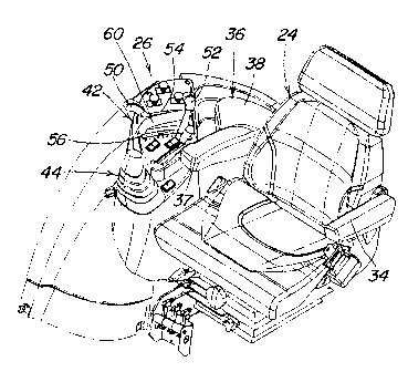
Figure 2 is a fragmentary perspective view of the armrest and control
panel of the compact tractor shown in Figure 1;

CA 02400020 2002-08-28
Figure 3 is a schematic plan view of the armrest and control panel of
the present invention showing an operator's range of arm movement;
Figure 4 is a sectional view taken generally along line 4-4 of Figure 3;
Figure 5 is a fragmentary perspective view of the armrest and control
panel of the present invention; and
Figure 6 is another fragmentary perspective view of the armrest and
control panel of the present invention.
Detailed Description Of The Preferred Embodiments
While this invention is susceptible of embodiment in many different
forms, there are shown in the drawings, and will be described herein in
detail,
specific embodiments thereof with the understanding that the present
disclosure is to be considered as an exemplification of the principles of the
invention and is not intended to limit the invention to the specific
embodiments
illustrated.
Figure 1 illustrates a utility vehicle 10 such as a compact tractor
including a chassis or frame 14 supported on front wheels 16 and larger rear
wheels 18. A floor and fender structure 20 is supported on the frame 14 and
carries a seat 24 and controls 26.
Figure 2 illustrates the operator seat 24 including a left armrest 34 and
right armrest 36. Adjacent to the right armrest 36 is a control panel 42 which
carries the controls 26. A selective control valve boot 44 is shown, the
selective control valve lever extending from the boot is not shown for clarity
of
description of the controls 26. Among the controls 26 on the control panel 42
are rock shaft, or three point hitch, control lever 52 and remote control
valve

CA 02400020 2002-08-28
lever 50. These levers actuate in forward and reverse directions through slots
54, 56, respectively. Between the slots 54, 56, a control hand reference 60 is
mounted to the panel 42.
The armrest 36 includes a support region 37 that is substantially flat
and elongated horizontally in a substantially rearward to forward direction.
The elbow-supporting region 38 fans rearward from the support region 37.
The elbow-supporting region 38 includes a downward slope in a fanning-
direction toward the control panel 42 which allows for a slight downward
tilting
of the forearm to control the controls without interfering with the arm. The
elbow-supporting region 38 also extends rearward sufficiently to allow forearm
support for an operator who is turning toward the back during operation of
rear tools or accessories.
As shown in Figure 3, the controls 26, including the associated slots
54, 56, and the levers 50, 52 are arranged in a substantially circular segment
path given a center point or fulcrum marked "X" on the elbow-supporting
region 38. An operator's forearm 70 is shown in phantom, including an elbow
72 and a hand 74. The fulcrum is located to be associated with the operator's
elbow 72, allowing the operator a swinging motion of his forearm about the
fulcrum X through an angle R to comfortably engage all of the controls 26.
The operator can rest his hand 74 on the control hand reference 60 during
operation of the utility vehicle and can operate the levers 50, 52 with his
hand
partially engaged to the control hand reference 60.
The armrest is secured to the seat by a an L-shaped bracket 39 welded
to the seat back and fastened with fasteners 41 into a side of the elbow-
supporting portion 38. The elbow-supporting portion 38 is declined from the
4

CA 02400020 2002-08-28
arm supporting surface 37. The armrest 36 can comprise a padded interior
covered by a vinyl or leather skin.
Figure 4 illustrates the operator's forearm 70 (in phantom) with the
elbow 72 supported on the elbow-supporting portion 38 and the hand 74
resting on the hand reference 60. In order to allow for an unrestricted or
downward movement to access the controls 26, the elbow-supporting portion
38 is sloped downwardly by the angle A (to the horizontal) which is greater
than the downward tilt of the forearm, generally the angle B (to the
horizontal).
As illustrated in Figures 5 and 6 the elbow-supporting portion 38 is
declined toward the controls 26. Lines of downward slope "s" are shown to
illustrate the general contour of the elbow=supporting portion 38. The elbow-
supporting portion 38 is sized to ergonomically receive the elbow of different
size operators. For example, the points X1 and X2 can also be fulcrums for
different-size operators which allow for comfortable swinging of the
operator's
arm to reach the controls 26.
From the foregoing, it will be observed that numerous variations and
modifications may be effected without departing from the spirit and scope of
the invention. It is to be understood that no limitation with respect to the
specific apparatus illustrated herein is intended or should be inferred. It
is, of
course, intended to cover by the appended claims all such modifications as
fall within the scope of the claims.

Representative Drawing
A single figure which represents the drawing illustrating the invention.
Administrative Status

2024-08-01:As part of the Next Generation Patents (NGP) transition, the Canadian Patents Database (CPD) now contains a more detailed Event History, which replicates the Event Log of our new back-office solution.

Please note that "Inactive:" events refers to events no longer in use in our new back-office solution.

For a clearer understanding of the status of the application/patent presented on this page, the site Disclaimer , as well as the definitions for Patent , Event History , Maintenance Fee  and Payment History  should be consulted.

Event History

Description Date
Inactive: IPC assigned 2024-06-19
Inactive: IPC expired 2024-01-01
Inactive: IPC removed 2023-12-31
Inactive: IPC deactivated 2019-01-19
Inactive: IPC from PCS 2018-01-27
Inactive: First IPC from PCS 2018-01-27
Inactive: IPC expired 2018-01-01
Time Limit for Reversal Expired 2010-08-30
Letter Sent 2009-08-28
Grant by Issuance 2007-04-24
Inactive: Cover page published 2007-04-23
Inactive: Final fee received 2007-02-07
Pre-grant 2007-02-07
Notice of Allowance is Issued 2006-08-09
Letter Sent 2006-08-09
Inactive: Approved for allowance (AFA) 2006-07-27
Letter Sent 2004-06-14
Amendment Received - Voluntary Amendment 2004-05-28
Request for Examination Requirements Determined Compliant 2004-05-28
All Requirements for Examination Determined Compliant 2004-05-28
Request for Examination Received 2004-05-28
Application Published (Open to Public Inspection) 2003-02-28
Inactive: Cover page published 2003-02-27
Inactive: IPC assigned 2002-11-27
Inactive: First IPC assigned 2002-11-27
Inactive: Filing certificate - No RFE (English) 2002-10-04
Letter Sent 2002-10-04
Application Received - Regular National 2002-10-04

Abandonment History

There is no abandonment history.

Maintenance Fee

The last payment was received on 2006-08-04

Note : If the full payment has not been received on or before the date indicated, a further fee may be required which may be one of the following

  • the reinstatement fee;
  • the late payment fee; or
  • additional fee to reverse deemed expiry.

Patent fees are adjusted on the 1st of January every year. The amounts above are the current amounts if received by December 31 of the current year.
Please refer to the CIPO Patent Fees web page to see all current fee amounts.

Fee History

Fee Type Anniversary Year Due Date Paid Date
Registration of a document 2002-08-28
Application fee - standard 2002-08-28
Request for examination - standard 2004-05-28
MF (application, 2nd anniv.) - standard 02 2004-08-30 2004-08-04
MF (application, 3rd anniv.) - standard 03 2005-08-29 2005-08-09
MF (application, 4th anniv.) - standard 04 2006-08-28 2006-08-04
Final fee - standard 2007-02-07
MF (patent, 5th anniv.) - standard 2007-08-28 2007-07-30
MF (patent, 6th anniv.) - standard 2008-08-28 2008-07-31
Owners on Record

Note: Records showing the ownership history in alphabetical order.

Current Owners on Record
DEERE & COMPANY
Past Owners on Record
JOHN RAYMOND ARTHUR
RUSSELL WILLIAM STRONG
Past Owners that do not appear in the "Owners on Record" listing will appear in other documentation within the application.
Documents

To view selected files, please enter reCAPTCHA code :


To view images, click a link in the Document Description column. To download the documents, select one or more checkboxes in the first column and then click the "Download Selected in PDF format (Zip Archive)" or the "Download Selected as Single PDF" button.

List of published and non-published patent-specific documents on the CPD .

If you have any difficulty accessing content, you can call the Client Service Centre at 1-866-997-1936 or send them an e-mail at CIPO Client Service Centre.


Document
Description 
Date
(yyyy-mm-dd) 
Number of pages   Size of Image (KB) 
Representative drawing 2002-12-10 1 22
Drawings 2002-08-27 4 124
Description 2002-08-27 5 197
Abstract 2002-08-27 1 15
Claims 2002-08-27 2 45
Claims 2004-05-27 3 112
Representative drawing 2007-04-04 1 25
Courtesy - Certificate of registration (related document(s)) 2002-10-03 1 109
Filing Certificate (English) 2002-10-03 1 161
Reminder of maintenance fee due 2004-04-28 1 109
Acknowledgement of Request for Examination 2004-06-13 1 176
Commissioner's Notice - Application Found Allowable 2006-08-08 1 162
Maintenance Fee Notice 2009-10-12 1 170