Note: Descriptions are shown in the official language in which they were submitted.
CA 02400153 2002-08-15
PATENT
Attorney Docket No. 032553-023
DEVICE AND METHOD FOR PRODUCING
HOLLOW PLASTIC BODIES
BACKGROUND
Field of the Invention
(0001] The invention relates to an apparatus for producing
hollow bodies of thermoplastic, as generically defined by the preamble
to claim 1. The invention also relates to a method for producing
hollow bodies of a thermoplastic, as generically defined by the
preamble to independent method claim 13.
[0002] The containers of tinned sheet-iron or mixed sheet
metal, glass, or ceramic that were typical in the past are increasingly
being replaced with plastic containers. Especially for packaging fluid
substances, such as beverages, oil, cleaning utensils, cosmetics, and so
forth, plastic containers are used primarily. The low weight and lower
costs surely play a not inconsiderable role in this substitution. The use
of recyclable plastic materials and the overall more-favorable total
expenditure of energy for producing them also contribute to increasing
consumer acceptance of plastic containers, especially plastic bottles.
[0003] The production of plastic containers, especially plastic
bottles, is done by extrusion blowing, in particular hollow body
blowing, for instance tubular film blowing. In this process, a preform
such as a tube, extruded in a single layer or multiple layers, is placed
in blow molds, inflated by overpressure via a blow mandrel, and
hardened by cooling. The automatic blow molder used for this
purpose as a rule has a plurality of parallel-connected blow molds,
which make it possible to produce a plurality of plastic containers
simultaneously in one operation. Each blow mold is assigned a
separate blow mandrel, which can be put into position in a way
suitable for the process.
[0004] In many cases, hollow plastic bodies, such as bottles or
canisters, but also industrial parts, have one or more openings, which
are for a particular purpose in later use. Often such openings are
-1-
CA 02400153 2002-08-15
PATENT
Attorney Docket No. 032553-023
embodied such that they are closable by suitable closing devices.
These can for instance be screw closures or snap closures. An
essential demand the closing technology must meet is tightness to
liquids, gases and solids in powdered or granular form. In plastic
packages, the tightness is typically achieved by creating smooth,
dimensionally accurate sealing faces adapted to one another in both the
hollow body and the closure. It is known that the sealing quality can
be improved still further by the choice of the correct combination of
materials for the hollow body and the closure.
[0005] Producing openings designed in this way typically is
done simultaneously with the process of producing the hollow body.
In it, the opening for introducing the inflation medium that generates
the overpressure, which in most cases is compressed air, is designed at
the same time such that it also meets the later demands made in terms
of the use of the hollow body. In these cases, the sealing faces, which
can be present both on the end face and on the preferably cylindrical or
conical inner wall of a neck extending around the edge of the opening,
must be produced. This is done in a so-called calibration operation,
that is, by means of a dimensional adaptation of a portion of the blow
mandrel, acting as a calibrating device, with the orifice region of the
blow molds and with the predetermined wall thickness of the preform
placed in the blow molds. The blowing and calibration mandrel
furthermore has the task of pinching off process- created protruding
parts of the preform in the upper edge region of the orifice, except for
a minimal residual thickness of the hollow body, so that they can be
pinched off perfectly in a deburring process following the inflation
operation.
[0006] For both operations, that is, calibrating the opening and
pinching off protruding parts, it is necessary for the blowing and
calibration mandrel to assume a very accurate, replicable position in
-2-
CA 02400153 2002-08-15
PATENT
Attorney Docket No. 032553-023
three planes relative to the orifice of the blow mold. In particular, the
axis of the blowing and calibration mandrel must match the axis of the
orifice of the cavity in the blow mold; the cutting ring face of the
blowing and calibration mandrel must be parallel to the neck blade face
of the blow mold, and the terminal height position of the blowing and
calibration mandrel relative to the orifice of the blow mold must
always assume exactly the position in which not only the dimensional
tolerances of the finished hollow body are adhered to but also the
pinching off of the protruding parts is assured. In practice, this is
achieved by adjusting a mechanical end stop for the blowing and
calibration mandrel. The adjustment is done manually, in accordance
with a visual assessment of the pinching-off operation and dimensional
checking of the orifice of the hollow body by the operator or operators.
In a single blowing device that has only a single blowing and
calibration mandrel, both demands in terms of quality can still be met
relatively simply and simultaneously with regard to the opening and to
the protruding parts. In automatic blow molders with a plurality of
parallel blow molds and blowing and calibration mandrels associated
with them, however, the adjusting operation can be accomplished only
with great difficulty and is very time-consuming. In view of the
demands for quality made of the pinching-off operation, the individual
blowing and calibration mandrels must all be adjusted to the correct
height relative to the orifices of the cavities in the blow molds. In this
respect it must be noted that dimensional differences at the orifices of
the individual blow molds, already dictated by the usual production
tolerances or by wear, make different height adjustments of the
blowing and calibration mandrels unavoidable. Because of the risk of
injury to the operator, the mechanically cooperating components of
these multiple automatic blow molders are protected against
unauthorized or unintentional access by covering devices. However,
-3-
CA 02400153 2005-05-02
these protective structural provisions are an obstacle to practicable
adjustment, which should advantageously be done with the machine
running.
[0007] It is therefore the object of the present invention to
overcome these disadvantages of the apparatuses in the prior art. An
apparatus for producing hollow bodies of plastic is to be created in
which the adjustment operations are simplified, and safe, malfunction-
free production of hollow bodies, especially plastic bottles and similar
containers, of the desired quality is made possible.
[0008a] In a broad aspect, the present invention relates to an
apparatus for producing hollow bodies, in particular bottles and similar
containers provided with an evacuation opening, of thermoplastic,
having a lower machine part (2) that has at least two blow molds (3a,
3b, 3c) each provided with a cavity (4), and having a beamlike upper
machine part (7), disposed above the lower machine part (2), on which
upper part a number of blowing and calibration mandrels (8a, 8b, 8c)
corresponding to the number of blow molds (3a, 3b, 3c) is disposed,
each being associated with one blow mold and being jointly feedable
toward the blow molds axially and being movable with their calibration
region into an orifice (5) of the cavities (4) until an annular shoulder
(9) of the blowing and calibration mandrels (8a, 8b, 8c) comes into
contact with a counterpart face (6) on the respective associate blow
mold (3a, 3b, 3c), characterized in that the blowing and calibration
mandrels (8a, 8b, 8c) are retained in the upper machine part (7) axially
freely movably within predeterminable limits, and upon feeding of the
blowing and calibration mandrels (8a, 8b, 8c) toward the blow molds
(3a, 3b, 3c) are automatically adjustable in height axially relative to
their outset position, counter to the resistance of a coupling medium
(H).
[0008b] In another broad aspect, the present invention relates to
a method for producing hollow bodies, in particular bottles or similar
-4-
CA 02400153 2005-05-02
containers provided with an evacuation opening, in a hollow body
blowing process, in which preforms extruded in a single layer or
multiple layers of a thermoplastic, for instance segments of a hose, are
placed in blow molds (3a, 3b, 3c) and then simultaneously, by means
of a blowing and calibration mandrel (8a, 8b, 8c) assigned to each
blow mold (3a, 3b, 3c) are inflated by overpressure in accordance with
the cavities (4) enclosed by the blow molds, and the evacuation
openings of the hollow bodies are calibrated, and parts protruding past
the evacuation necks are pinched off, and finally the unmolded hollow
bodies are hardened by cooling, characterised in that the blowing and
calibration mandrels (8a, 8b, 8c), during the pinching-off operation, in
which an encompassing annular shoulder (9) on each blowing and
calibration mandrel is pressed against a counterpart face (6) on the
associated blow mold, are automatically adjusted axially in height
relative to their outset position, within predetermined limits, counter to
the restoring force of a coupling medium (H).
[0009] An apparatus for producing hollow bodies, in particular
bottles and similar containers provided with an evacuation opening, of
thermoplastic includes a lower machine part and a beamlike upper
machine part. The lower machine part is equipped with at least two
blow molds, each provided with a cavity. A number of blowing and
calibration mandrels corresponding to the number of blow molds is
disposed on the beamlike upper machine part disposed above the lower
machine part. One blow mold is assigned to each blowing and
calibration mandrel. The blowing and calibration mandrels can be
jointly fed axially toward the blow molds and can be moved with their
calibration region into an orifice of the cavity until an annular shoulder
of the blowing and calibration mandrels comes into contact with a
counterpart face on the associated blow mold. According to the
invention, the blowing and calibration mandrels are retained axially
-4a-
CA 02400153 2002-08-15
PATENT
Attorney Docket No. 032553-023
freely movably, within predeterminable limits, in the upper machine
part. When the blowing and calibration mandrels are fed jointly toward
the blow molds, the blowing and calibration mandrels are automatically
adjustable in height relative to their outset position, counter to the
resistance of a coupling medium.
[0010] Because the blowing and calibration mandrels are
supported limitedly axially adjustably in the upper machine part and
are automatically adjustable in height upon being fed toward the blow
molds, the tedious process of performing the adjustment manually can
be dispensed with. By the self adjustment of the blowing and
calibration mandrels, it is assured that the encompassing annular
shoulders on all the blowing and calibration mandrels are pressed with
the same pressing force against the associated counterpart faces on the
blow molds. Thus to assure clean pinching off of material protruding
from the preform, only the feeding device has to be set up once and for
all, for all the blowing and calibration mandrels. The self-adjustment
of the blowing and calibration mandrels takes place automatically,
counter to the restoring force of coupling media. Once adjusted
automatically with respect to height, the mount of the blowing and
calibration mandrels assures that the correct adjustment is maintained.
On the other hand, the holding force of the mounts does not hinder an
automatic readjustment, for instance required because of gradual wear
to the cooperating faces that occurs during long-term operation. As an
additional effect of the somewhat elastic adjustability, damping of the
feeding operation ensues, which has advantages in terms of wear of the
cooperating annular shoulders and counterpart faces.
[0011] In an advantageous variant of the invention, the blowing
and calibration mandrels are coupled hydraulically to one another. By
the hydraulic coupling of the blowing and calibration mandrels, the
pressure compensation and the height adjustability of the blowing and
-5-
CA 02400153 2002-08-15
PATENT
Attorney Docket No. 032553-023
calibration mandrels can be regulated quite simply. The hydraulically
coupled blowing and calibration mandrels cooperate with adjusting
pistons, which are limitedly displaceable axially inside bores in the
upper machine part. The pistons are short-circuited to one another by
means of a hydraulic fluid, which forms the coupling medium and is
disposed inside a reservoir that communicates with the bores. As a
result of the disposition according to the invention, all the blowing and
calibration mandrels communicate with one another via a
communicating vessel. From the moment a reaction force takes effect
onward, an equalization of height occurs, until all the blowing and
calibration mandrels exert the same force on a part to be pinched off.
For instance, standard hydraulic oil is used. A degassing device for
the hydraulic oil may be provided. When the hydraulic oil is dispensed
in the exclusion of air after prior evacuation of the system, then a
degassing device can be omitted.
[0012] To take appropriate account of the usual production
tolerances, wear, and the requisite variously high cutting devices for
various materials, the self-adjusting blowing and calibration mandrels
have an axial height adjustability relative to their outset position that
can amount for instance to about ~ 4 mm, and in a variant of the
invention preferably about ~2.5 mm. Naturally, still greater axial
adjustment ranges can also be provided.
[0013] For reasons of assembly technology and because of
simple maintenance, the blowing and calibration mandrels are retained
releasably in the beamlike upper machine part. They are
advantageously fixed in their mounts by clamping. Fastening the
blowing and calibration mandrels by clamping has the advantage that
even deviations from the set-point outside diameter can be compensated
for quite simply. Warping, as can occur in conventional screw
mounts, in particular, is avoided.
-6-
CA 02400153 2002-08-15
PATENT
Attorney Docket No. 032553-023
[0014] One not inconsiderable advantage of the clamping mount
is that it offers the capability of fixing all the blowing and calibration
mandrels in their mounts with the same clamping force, regardless of
any external dimensional tolerances that occur. The clamping force is
selected such that the blowing and calibration mandrels cannot adjust
unintentionally because of their weight and the dynamic forces
involved in the processes of motion, but can be adjusted in the desired
way by the action of the hydraulic forces. The blowing and calibration
mandrels are preferably prevented from falling out of the upper
machine part by means of stops.
[0015] A quite expedient structural variant of the clamping
mount includes a retaining nut, which is provided with a male thread
and can be screwed into a threaded bore in the upper machine part.
The retaining nut has a conical face, which cooperates with a radially
compressible clamping element, preferably a slit cone provided vi~ith a
conical counterpart face and comprising an elastic, wear-resistant
material, preferably of an industrial plastic. The cooperating conical
faces divert the force resulting from the tightening moment of the
retaining nut, and by the radial narrowing of the clamping element they
assure the requisite clamping force.
[0016] Because the clamping mount includes a prestressing
element, dimensional tolerances and nonuniformities in the
embodiment of the thread of the threaded bore in the upper machine
part and on the retaining nut can be compensated for. The prestressing
element is preferably formed by a cup spring, which in the put-together
state is braced on one end in the threaded bore and on the other,
optionally with the interposition of an underlay shim, on the clamping
element. The underlay shim has the advantage that the cup spring
cannot dig into the somewhat softer, radially compressible clamping
element. This reliably counteracts any mispositioning of the cup
CA 02400153 2002-08-15
PATENT
Attorney Docket No. 032553-023
spring.
[0017] The floating mounting of the blowing and calibration
mandrels in the upper machine part also offers the opportunity of
rotating them about their longitudinal axis, without shifting of the axial
positions set. This is advantageous for instance in blowing and
calibration mandrels that have a cross section other than circular in the
calibration region. For example, the blowing and calibration mandrels
have a calibration region of elliptical cross section.
[0018] For the sake of more easily putting blowing and
calibration mandrels with calibration regions of an other than circular
cross section into the correct position relative to the cavity in the blow
mold, positioning means are provided in the upper machine part and on
the blowing and calibration mandrels. The positioning means
preferably each include circumferential knurling or teeth on the
blowing and calibration mandrel and an externally actuatable adjusting
pin on the upper machine part. The circumferential knurling or teeth
can have either a uniform or a variable pitch, so as to adjust the
blowing and calibration mandrel in predetermined and even relatively
large increments. The adjusting pins serve to fix the oriented blowing
and calibration mandrels in the position set.
[0019] The stop shoulders on the blowing and calibration
mandrels are advantageously provided on interchangeably held cutting
rings. The cutting rings have especially hardened contact faces and
cutting edges, so that the pinching-off operation is effected cleanly and
reliably, and the wear to the cooperating components can be kept as
slight as possible. The interchangeability of the cutting rings makes
simple replacement possible as needed, or simple adaptation to
requirements, for instance resulting from different wall thicknesses of
the preforms.
[0020] With a view to modular construction and various
_g_
CA 02400153 2002-08-15
PATENT
Attorney Docket No. 032553-023
possibilities for use of the apparatus, it is also highly advantageous if
the calibrating portion of the blowing and calibration mandrel is
formed by an interchangeable calibration sleeve. The interchangeable
arrangement offers the opportunity as needed of fastening calibration
sleeves of relatively large diameter, or sleeves with a cross section
other than circular, for instance an elliptical cross section, to the
blowing and calibration mandrels in order to retrofit the apparatus
quite simply to the requirements of the particular hollow body to be
produced.
[0021] In a method for producing hollow bodies, in particular
bottles or similar containers provided with an evacuation opening, in a
hollow body blowing process, preforms extruded in a single layer or
multiple layers of a thermoplastic, for instance segments of a hose, are
placed in blow molds. The hollow bodies to be produced are inflated
by overpressure in accordance with the cavities enclosed by the blow
molds. The evacuation openings of the hollow bodies are calibrated,
and parts protruding past the evacuation necks are pinched off. Finally
the unmolded hollow bodies are hardened by cooling. According to
the invention, the blowing and calibration mandrels, during the
pinching-off operation, in which an encompassing annular shoulder on
each blowing and calibration mandrel is pressed against a counterpart
face on the associated blow mold, are automatically adjusted axially in
height relative to their outset position, within predeterminable limits,
counter to the restoring force of a coupling medium.
[0022] The automatic self adjustment of the blowing and
calibration mandrels saves the operator the inconvenient, time-
consuming and in some cases potentially dangerous adjustment
procedure. It suffices if the feeding device on the upper machine part
is set in a single adjusting step. The automatic reregulation of the
height of the blowing and calibration mandrels assures that the critical
-9-
CA 02400153 2002-08-15
PATENT
Attorney Docket No. 032553-023
operative faces on the encompassing annular shoulders of the blowing
and calibration mandrels will all be disposed at the same height and
also assures uniform imposition of pressure on the counterpart faces at
the orifices of the cavities in the blow molds.
[0023] Because the blowing and calibration mandrels are short-
circuited to one another by a hydraulic fluid operated in the spring
range, a gentle height adjustment and in particular a damped delivery
of the blowing and calibration mandrels to the associated blow molds
are assured. The hydraulic short circuit causes a pressure
compensation by way of the number of blowing and calibration
mandrels, which is expressed in the fact that some of the blowing and
calibration mandrels are adjusted in one axial direction, while the
others are adjusted for compensatory purposes in the opposite
direction.
[0024] The blowing and calibration mandrels are
advantageously held by clamping in their floating outset position on the
beamlike upper machine part. The mount is embodied releasably. A
decisive factor for the pressure compensation over the entire number of
blowing and calibration mandrels is that each blowing and calibration
mandrel is held with the same clamping force. The clamping force is
advantageously selected such that the blowing and calibration mandrels
are secured against unintended falling out of their clamping mounts,
while their axial height adjustability is impaired only insignificantly. It
is especially advantageous if the clamping force is selected as precisely
great enough that a correct self adjustment of the axial height of the
blowing and calibration mandrels once effected is maintained counter
to the restoring force of the hydraulic fluid. The clamping force is
defined by the tightening moment of the mounts for the blowing and
calibration mandrels in the beamlike upper machine part, which can be
adjusted quite simply by the operators and maintenance staff, for
-10-
CA 02400153 2002-08-15
PATENT
Attorney Docket No. 032553-023
instance by using a suitable torque wrench. The effective value of the
clamping force then depends on the structural design of the mounting
device.
BRIEF DESCRIPTION OF THE DRAWINGS
[0025) The invention will be described below in terms of an
exemplary embodiment shown in the drawings. In partly schematic
views not to scale, the drawings show:
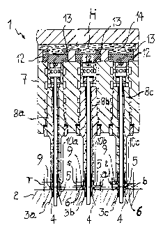
[0026] Fig. 1, a portion of the apparatus of the invention, with
an arrangement of three blowing and calibration mandrels, in their
outset position;
[0027) Fig. 2, the blowing and calibration mandrels of Fig. 1
once self adjustment has occurred;
[0028] Fig. 3, a upper machine pan with an arrangement of
two blowing and calibration mandrels, far the sake of illustrating their
floating mounting; and
[0029] Fig. 4, a cross section through a blowing and calibration
mandrel taken along the line IV-IV in Fig. 3.
DETAILED DESCRIPTION OF THE
PREFERRED EMBODIMENTS
[0030] An apparatus, embodied according to the invention, for
producing hollow bodies, in particular bottles and similar containers
provided with an evacuation opening, of thermoplastic is identified in
its entirety in Fig. 1 by reference numeral 1. In particular, this
apparatus is a so- called automatic blow molder, in which the desired
hollow body is produced from a preform by inflation in a mold. The
apparatus 1 includes a lower machine part 2 and a upper machine part
7. The lower machine part 2 is embodied in table-like form and is
equipped with a number of blow molds, which in Fig. 1 are identified
by reference numerals 3a, 3b and 3c. The blow molds 3a, 3b and 3c
each enclose one cavity 4, which defines the later form of the hollow
-11-
CA 02400153 2002-08-15
PATENT
Attorney Docket No. 032553-023
body to be produced. The cavities 4 open out to the top of the table-
like lower machine part 2, where they have orifices 5 oriented toward
the upper machine part 7.
[0031] A plurality of blowing and calibration mandrels 8a, 8b,
8c are mounted side by side on the upper machine part 7, which is
embodied in beamlike form. The number of blowing and calibration
mandrels 8a, 8b, 8c corresponds to the number of blow molds 3a, 3b,
3c in the lower machine part 2. Each blowing and calibration mandrel
is assigned precisely one blow mold. The upper machine part 7 is
equipped with feeding devices, not identified by reference numeral,
with the aid of which the blowing and calibration mandrels 8a, 8b, 8c
can be axially fed jointly toward the blow molds 3a, 3b, 3c in such a
way that they dip with their calibration regions into the orifices 5 in the
blow molds 3a, 3b, 3c. The feeding motion continues until an
encompassing annular shoulder 9 disposed on the blowing and
calibration mandrels 8a, 8b, 8c presses with a predeterminable force
against a counterpart face 6 that is provided on each of the blow molds
3a, 3b, 3c and that extends around the periphery of the orifice 5 of the
cavity 4. In this way, material of a preform, and placed in the cavity
4, such as an inflated single- or multi-layer tube, that protrudes past
the blow molds 3a, 3b, 3c can be pinched off.
[0032] The annular shoulders 9 in the exemplary embodiment
shown are provided on cutting rings 10a, 10b, 10c, which are mounted
interchangeably on the blowing and calibration mandrels 8a, 8b, 8c.
[0033] The cutting rings 10a, 10b, lOc can have different
heights r, s, t, which are dictated for instance by production tolerances
or result from different wear. The different heights r, s, t of the
cutting rings 10a, 10b, lOc are shown somewhat exaggerated in Fig. 1,
in order to illustrate the resulting effect clearly. When the annular
shoulder 9 of the blowing and calibration mandrel 8a is already pressed
-12-
CA 02400153 2002-08-15
PATENT
Attorney Docket No. 032553-023
against the counterpart face 6 of the associated blow mold 3a, the
annular shoulders 9 of the other two blowing and calibration mandrels
8b, 8c are still at the spacing a and b, respectively, from the
counterpart faces 6 of the associated blow molds 3b, 3c, because of the
lesser heights s, t of the cutting rings lOb, lOc. In the apparatuses of
the prior art, the height of the blowing and calibration mandrels 8b, 8c
therefore had to be changed in an inconvenient adjusting process, in
order to compensate for different heights r, s, t of the cutting rings
10a, lOb, 10c and to assure secure pinching off of protruding material
at all the blow molds 3a, 3b, 3c. In this respect it must be taken into
account that automatic blow molders can have up to ten or even more
blowing and calibration mandrels with associated blow molds, for the
sake of producing hollow bodies on a mass-production basis and
economically. With the number of blowing and calibration mandrels,
the effort of adjustment naturally also increases. This means
downtimes of the automatic blow molder that are multiple times longer
and also means an increased risk to operators in the case of adjusting
height with the machine running.
[0034] In the apparatus 1 embodied according to the invention,
the blowing and calibration mandrels 8a, 8b, 8c each cooperate, on
their respective end portion supported in the upper machine part 7,
with adjusting pistons 12, which are axially displaceable to a limited
extent inside bores 13 in the upper machine part 7. The bores 13
communicate with a conduit 14, which acts as a reservoir for a
hydraulic fluid H, by way of which the blowing and calibration
mandrels 8a, 8b, 8c are short-circuited. The hydraulic fluid H is put
under pressure in the spring range by the axially adjusted pistons 12.
(0035] By the feeding of the blowing and calibration mandrels
8a, 8b, 8c against the blow molds 3a, 3b, 3c, the shoulders 9 are
supposed to be pressed against the counterpart faces 6. As soon as the
-13-
CA 02400153 2002-08-15
PATENT
Attorney Docket No. 032553-023
shoulder 9 of the first blowing and calibration mandrel 8a is pressed
with a certain force against the counterpart face 6 of the associated
blow mold 3a, the blowing and calibration mandrel 8a is displaced
axially, and the adjusting piston 12 migrates upward. The axial
displacement is effected counter to the resistance of the hydraulic fluid.
The pressure transmitted to the hydraulic fluid H is distributed,
because of the short circuit, to the adjusting pistons 12 of the other
blowing and calibration mandrels 8b, 8c, and as a result these blowing
and calibration mandrels are axially displaced more or less far
compared to their outset position.
[0036] Fig. 2 shows the position of the blowing and calibration
mandrels 8a, 8b, 8c after the self-adjustment. The blowing and
calibration mandrel 8a with the cutting ring 10a having the greatest
height r has been shifted to the rear, into the upper machine part 7. By
the pressure exerted on the hydraulic fluid H, the blowing and
calibration mandrel 8c with the cutting ring lOc having the least height
t has in turn been pushed outward in the opposite direction, toward the
associated blow molding mechanism 3c. The middle blowing and
calibration mandrel 8b has essentially remained in the same axial
position and, with the location of its annular shoulder 9, it dictates the
set-point location of the other annular shoulders. The axial height
adjustability of the blowing and calibration mandrels 8a, 8b, 8c
compared to their outset position amounts for instance to about 4 mm.
In a variant of the invention, the axial adjustment range can be
selected as about 2.5 mm. It is understood that even greater height
adjustment ranges can be provided. The hydraulic fluid H has a
certain elastic compressibility, which upon initiation of force via the
pistons 12 brings about a certain damping.
[0037] Fig. 3 shows a portion of the upper machine part 7 with
two of the blowing and calibration mandrels 8a, 8b, preferably
-14-
CA 02400153 2002-08-15
PATENT
Attorney Docket No. 032553-023
disposed in series, on a larger scale. Identical components have the
same reference numerals as in Figs. l and 2. The blowing and
calibration mandrel 8a on the left is shown taken apart, to clearly
illustrate the structure of its floating mounting. On the blowing and
calibration mandrel 8b on the right, the elements of its mount are
shown in the assembled state. In the exemplary embodiment shown,
the blowing and calibration mandrels 8a, 8b are secured to the
beamlike upper machine part 7 by a clamping mount such that they
float with limited axial displaceability. The clamping mount comprises
a retaining nut 16, which is provided with a male thread and can be
screwed into a threaded bore 15 in the upper machine part 7. The
retaining nut 16 cooperates via a conical face 20 with a radially
compressible clamping element 17. The clamping element 17 is
preferably a slit cone of an elastic, wear- resistant material, for
instance an industrial plastic. The cone is equipped with a counterpart
face 21. The retaining nut 16 and the clamping element 17 are kept
prestressed by a cup spring 19, which is braced on one end in the
threaded bore 15 and on the other on an underlay shim 18 placed
between the cup spring 19 and the clamping element 17.
[0038] The retaining nut 16 is screwed with a predetermined
tightening moment into the threaded bore 15. A torque wrench is used
for the purpose, for instance. The clamping force transmitted to the
blowing and calibration mandrels 8a, 8b depends on the force boast by
the conical faces 20, 21 and the dimensions of the clamping element
17. The effective clamping force also depends on the coefficients of
friction of the cooperating faces of the blowing and calibration
mandrels 8a, 8b and clamping elements 17. In each case, the clamping
force must be at least great enough that the blowing and calibration
mandrels 8a, 8b do not fall out of their mounts on the upper machine
part 7 but instead continue to be held in floating fashion.
-15-
CA 02400153 2002-08-15
PATENT
Attorney Docket No. 032553-023
Advantageously, the clamping force is precisely great enough that the
automatic axial adjustment of the blowing and calibration mandrels 8a,
8b is not significantly hindered by the hydraulic forces that occur upon
feeding toward the lower machine part. On the other hand, the
clamping force suffices to prevent the blowing and calibration
mandrels 8a, 8b from shifting unintentionally because of their weight
and the dynamic forces involved in the movement processes. The
tightening moment for the retaining nut 16 is dependent directly on the
cone angle selected. As a result, a frictional force that is greater than
the forces of inertia and that nevertheless still allows displacement of
the blowing and calibration mandrels 8a, 8b by the reaction force in
the pinching process is the goal. In a variant of the invention, the
tightening moment is selected for instance as about 20 Nm to about 40
Nm, and preferably about 25 Nm to 35 Nm, and especially preferably
about 31 Nm.
[0039] The calibration region at the front of the blowing and
calibration mandrels 8a, 8b, in the exemplary embodiment shown, is
embodied in each case by a calibration sleeve 11 mounted
interchangeably, for instance being screwed in. As a result, this sleeve
can easily be taken out as needed and replaced. The cutting rings 10
are also interchangeably mounted and are braced on a free front end of
the blowing and calibration mandrel 8a, 8b and on a shoulder on the
circumference of the calibration sleeve 11.
[0040] Because of the floating mounting of the blowing and
calibration mandrels 8a, 8b, the possibility also exists as needed of
mounting calibration sleeves 11 with an other than circular cross
section, for instance elliptical calibration sleeves, and orienting them
quite simply with the cavities in the blow molds, so that in particular
the axes of the blowing and calibration mandrels Sa, Sb match the axes
of the necks of the cavities. To that end, positioning means are
-16-
CA 02400153 2002-08-15
PATENT
Attorney Docket No. 032553-023
provided, which enable a controlled rotation of the blowing and
calibration mandrels about their longitudinal axis. The positioning
means include an adjusting pin 23 in the upper machine part 7, which
cooperates with circumferential knurling or external teeth 22 on the
blowing and calibration mandrels 8a, as shown in suggested fashion in
Fig. 4. The circumferential knurling or teeth 22 can have either a
uniform or a nonuniform pitch, so that the blowing and calibration
mandrels 8a can be adjusted in rotated fashion in predetermined and
even relatively large increments. The adjusting pin 23 serves to fix the
oriented blowing and calibration mandrel 8a in the position set.
-17-