Note: Descriptions are shown in the official language in which they were submitted.
CA 02400354 2002-08-15
SPECIFICATION
METHOD OF RECOVERING ENRICHED GASEOUS OXYGEN
TF.CHNTCAT, FTELD
The present invention relates to a method of recovering
enriched gaseous oxygen from a crude gas containing oxygen by
pressure swing adsorption (PSA process).
BACKGROUND ART
Oxygen-rich gas, i.e. gaswith a high oxygen concentration,
obtained by a PSA process is widely utilized for technical
fields which require continuous supply of oxygen, i.e. for
electric steel making, water treatment by oxygen aeration, pulp
bleaching or ozonizers for example. Recently, also in the
technical field of combustion, resort is made to combustion
in oxygen-rich gas instead of combustion in the air for melting
furnace residues, for providing a lower NOx emission or for
enhancing efficiency of chemical reaction for example.
Moreover, oxygen-rich gas is widely utilized also in the field
of biochemistry such as fermentation.
A typical PSA process is a multi-tower PSA process which
utilizes an apparatus provided with at least two adsorption
towers. In the multi-tower PSA process, the process steps of
adsorption, desorption and pressurization are repeated in each
of the adsorption towers. These process steps are performed
in the adsorption towers at different timings from each other.
1
CA 02400354 2002-08-15
Various attempts have been made for the improvement of such
a multi-tower PSA process and an apparatus used therefor. For
example, JP-A-8-239204 discloses a process in which the
pressure in an adsorption tower in which adsorption is finished
is utilized for pressuring another adsorption tower.
On the other hand, a single tower PSA process which
utilizes an apparatus provided with a single adsorption tower
is also known as a process for realizing size-reduction,
simplification of the apparatus and initial cost reduction.
Various attempts have been made also for the improvement of
such a single tower PSA process and an apparatus used therefor
with respect to the amount and purity of oxygen gas obtained
as a product. For example, JP-A-9-29044 discloses a process
in which the gas remaining in the adsorption tower upon
finishing the adsorption is recovered in a separately provided
recovery tank and is returned to the adsorption tower when the
desorption is finished for washing the adsorption tower.
However, with the processes disclosed in the gazettes or
with other prior art single tower PSA processes, the recovery
of oxygen-rich gas is insufficient and there is still room for
improvement.
An object of the present invention, which is conceived
under the circumstances described above, is to enhance the
recovery of oxygen-rich gas in obtaining oxygen-rich gas by
a single tower PSA process.
2
CA 02400354 2002-08-15
nTSCrOSURE OF THE TNVENTION
According to a first aspect of the present invention,
there is provided a process for recovering oxygen-rich gas by
enriching gaseous oxygen contained in crude gas by a single
tower pressure swing adsorption which utilizes a single
adsorption tower loaded with an adsorbent. In this process,
a cycle is repeated which includes an adsorption step for
adsorbing an unnecessary component contained in the crude gas
by the adsorbent by introducing the crude gas into the
adsorption tower to output oxygen-rich gas from the adsorption
tower, a desorption step for desorbing the unnecessary
component from the adsorbent by depressurizing the adsorption
tower, a washing step for introducing washing gas into the
adsorption tower to discharge remaining gas in the adsorption
tower, and a pressurization step for raising the internal
pressure of the adsorption tower. The desorbing step includes
recovering semi-enriched oxygen gas existing in the adsorption
tower after the adsorption is finished for retention in a
recovery tank. The washing step includes introducing part of
the semi-enriched oxygen gas retained in the recovery tank into
the adsorption tower as the washing gas while discharging the
remaining gas from the adsorption tower. The pressurizing
step includes raising the internal pressure of the adsorption
tower by introducing the rest of the semi-enriched oxygen gas
retained in the recovery tank into the adsorption tower.
Preferably, the adsorption tower has a crude gas inlet
and a product gas outlet. In the desorption step, the
3
CA 02400354 2002-08-15
semi-enriched oxygen gas is recovered into the recovery tank
through the product gas outlet, whereas the unnecessary gaseous
component desorbed from the adsorbent is discharged through
the crude gas inlet.
Preferably, the washing step includes introducing part
of the oxygen-rich gas into the adsorption tower as the washing
gas while discharging the remaining gas from the adsorption
tower.
Preferably, the division ratio between the amount of the
semi-enriched oxygen gas to be introduced in the adsorption
tower in the washing step and the amount of the semi-enriched
oxygen gas to be introduced in the adsorption tower in the
pressurization step lies in the range of from 65:35 to 97:3
as calculated on the basis of standard state volume. More
preferably, the division ratio lies in the range of from 75:25
to 93:7 as calculated on the basis of standard state volume.
According to a second aspect of the present invention,
there is provided another process for recovering oxygen-rich
gas by enriching gaseous oxygen contained in crude gas by a
single tower pressure swing adsorption which utilizes a single
adsorption tower loaded with an adsorbent. In this process,
a cycle is repeated which includes an adsorption step for
adsorbing an unnecessary component contained in the crude gas
by the adsorbent by introducing the crude gas into the
adsorption tower for outputting oxygen-rich gas from the
adsorption tower, a first desorption step for desorbing the
unnecessary component from the adsorbent by depressurizing the
4
CA 02400354 2002-08-15
adsorption tower for discharging the unnecessary component
from the adsorption tower while recovering semi-enriched
oxygen gas existing in the adsorption tower for retention in
a recovery tank after the adsorption is finished, a second
desorption step for desorbing the unnecessary component from
the adsorbent out of the adsorption tower by depressurizing
the adsorption tower without recovering the semi-enriched
oxygen gas, a first washing step for introducing washing gas
into the adsorption tower while discharging remaining gas from
the adsorption tower, a second washing step for introducing
part of the semi-enriched oxygen gas retained in the recovery
tank into the adsorption tower while discharging the remaining
gas from the adsorption tower, and a pressurization step for
raising the internal pressure of the adsorption tower by
introducing the rest of the semi-enriched oxygen gas retained
in the recovery tank into the adsorption tower.
In the process for recovering oxygen-rich gas according
to the present invention, the semi-enriched oxygen gas existing
in the adsorption tower after the finishing of adsorption is
recovered for utilization both for the washing and the
pressurization of the adsorption tower. The inventors have
confirmed that such a process enhances the final recovery of
the oxygen-rich gas as compared with the case where the
recovered semi-enriched oxygen gas is utilized solely for the
washing of the adsorption tower or solely for the
pressurization of the adsorption tower.
5
CA 02400354 2002-08-15
The inventors have confirmed that a high recovery is
obtained in the case where the division ratio between the amount
of the semi-enriched oxygen gas to be introduced in the
adsorption tower in the washing step and the amount of the
semi-enriched oxygen gas to be introduced in the adsorption
tower in the pressurization step lies in the range of from 65 : 35
to 97:3, and preferably from 75:25 to 93:7 as calculated on
the basis of standard state volume.
Other features and advantages of the present invention
will become clearer from the detailed description given below
with reference to the accompanying drawings.
B T.F DFS RTPTTON OF THE DRAWTN GS
Fig. 1 schematically illustrates a PSA separation
apparatus X f or realizing an oxygen-rich gas recovering process
according to the present invention.
Fig. 2 is a table showing an opened/closed state of each
automatic valve of the PSA separation apparatus of Fig. 1 in
each step of the oxygen-rich gas recovering process.
Figs. 3A-3F illustrate gas flows in respective steps.
Fig. 4 is a table showing the conditions and data of the
examples and comparative examples.
Fig. 5 is a graph showing the results of the examples and
comparative examples.
6
CA 02400354 2002-08-15
BEST MODE FOR CARRYING OUT THE TNVENTTON
Preferred embodiments of the present invention will be
described below with reference to the accompanying drawings.
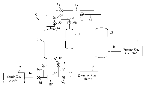
Fig. 1 schematically illustrates a PSA separation
apparatus X for realizing an oxygen-rich gas collecting process
according to the present invention. The PSA separation
apparatus X includes an adsorption tower 1, a product gas buffer
tank 2 and a recovery tank 3.
The adsorption tower 1, which includes a product gas
outlet la and a crude gas inlet lb, is loaded with an adsorbent.
As the adsorbent, use may be made of Li-X type zeolite molecular
sieve, Ca-X type zeolite molecular sieve or Ca-A type zeolite
molecular sieve for example.
The product gas outlet la of the adsorption tower 1 is
connected to the product gas buffer tank 2 via a first pipe
4a for product gas collection and via a second pipe 4b for
product gas supply. The product gas outlet is also connected
to the recovery tank 3 via a third pipe 4c for semi-enriched
oxygen gas, which will be described later.
The crude gas inlet lb of the adsorption tower 1 is
connected to a crude gas supply 7 via a common fourth pipe 4d
and a fifth and a sixth pipes 4e, 4f for crude gas supply. The
crude gas inlet is also connected to a desorbed gas collector
8 via the fourth pipe 4d, and a seventh and an eighth pipes
4g, 4h for desorbed gas discharge.
The product gas buffer tank 2 is connected to a product
gas collector 9 via a ninth pipe 4i for product gas collection.
7
CA 02400354 2002-08-15
The first pipe 4a for product gas collection is provided
with an automatic valve 5a, whereas the second pipe 4b for
product gas supply is provided with an automatic valve 5b and
a flow rate controlling valve 6a. The third pipe 4c for
semi-enriched oxygen gas is provided with an automatic valve
5c and a flow rate controlling valve 6b. The fifth and the
sixth pipes 4e, 4f for crude gas suppiy and the seventh and
the eighth pipes 4g, 4h for desorbed gas discharge are provided
with automatic valves 5d, 5e, 5f, 5g, respectively. The common
fourth pipe 4d is provided with a blower pump BP.
The gas flow in the first through the ninth pipes 4a-
4i is controlled by appropriately opening or closing each of
the automatic valves 5a-5g. In the adsorption tower 1, a
series of process steps including adsorption, desorption,
washing and pressurization are repeated a predetermined number
of times. The adsorption step is performed under an elevated
pressure for adsorbing unnecessary gas by the adsorbent. The
desorbing step is performed under a lowered pressure for
desorbing the unnecessary gas from the adsorbent. In the
washing step, the desorbed gas remaining in the tank is
discharged. In the pressurization step, the internal pressure
of the adsorption tower 1 is raised in preparation for the
adsorption step.
According to the embodiment, the PSA separation apparatus
X having the above-described structure is utilized for removing
unnecessary components from the crude gas for obtaining
oxygen-enriched product gas, or oxygen rich gas. In the
8
CA 02400354 2002-08-15
adsorption tower 1, a cycle including steps 1-6 shown in Fig.
2 is repeated. Fig. 2 also shows the open/close state of each
of the valves 5a-5g in each process step. Each of Figs. 3A-3F
illustrates the gas flow in a respective step. The gas flow
is indicated by a bold arrow.
In STEP 1, each of the automatic valves 5a-5g is opened
or closed as shown in Fig. 2 to provide the gas flow as shown
in Fig. 3A, thereby performing adsorption.
As shown in Figs. 1 and 3A, the adsorption tower 1
communicates with the crude gas supply 7. Further, the
adsorption tower 1 communicates also with the product gas
collector 9 via the product gas buffer tank 2. Therefore, by
the operation of the blower pump BP, the crude gas such as air
flows from the crude gas supply 7 through the fifth pipe 4e,
the third pipe 4d and the sixth pipe 4f for introduction into
the adsorption tower 1 via the crude gas inlet lb. At this
time, the internal pressure of the adsorption tower 1 is held
at 30-100kPa (gauge pressure) for example. In the adsorption
tower 1, unnecessary components contained in the crude gas,
including nitrogen for example, are adsorbed by the adsorbent
for removal. As a result, gas with a high oxygen concentration,
i.e. oxygen rich gas, flows out from the adsorption tower 1
via the product gas outlet la as a product gas. The product
gas is sent to the product gas buffer tank 2 through the first
pipe 4a. The product gas is once retained in the product gas
buffer tank 2 and then collected in the product gas collector
9 via the ninth pipe 4i. When this process step is finished,
9
CA 02400354 2002-08-15
part of the product gas remains in the product gas buffer tank
2.
In STEP 2, each of the automatic valves 5a-5g is opened
or closed as shown in Fig. 2 to provide the gas flow as shown
in Fig. 3B, thereby performing desorption.
As shown in Figs. 1 and 3B, the adsorption tower 1
communicates with the recovery tank 3. The internal pressure
of the adsorption tower 1 is raised to e.g. 30-100kPa (gauge
pressure) due to the adsorption previously performed therein.
On the other hand, in the initial stage of this step, the
internal pressure of the recovery tank 3 is kept relatively
low, which may lie in the range of from -80 to -10kPa (gauge
pressure) for example. Therefore, the gas with a relatively
high oxygen concentration existing in the adsorption tower 1,
i.e. the semi-enriched oxygen gas moves to the recovery tank
3 through the third pipe 4c due to the pressure difference
between the adsorption tower 1 and the recovery tank 3. Due
to its previous presence in the adsorption tower upon finishing
the adsorption process, this gas has undergone considerable
removal of unnecessary components and therefore has a
relatively high oxygen concentration. The internal pressure
of the recovery tank 3 finally lies in the range of from -
50 to 70kPa (gauge pressure).
In STEP 2, the adsorption tower 1 communicates also with
the desorbed gas collector 8. Thus, while the semi-enriched
oxygen gas moves to the recovery tank 3, the adsorption tower
1 is depressurized by the operation of the blower pump BP.
CA 02400354 2002-08-15
Therefore, unnecessary components are desorbed from the
adsorbent, increasing the unnecessary gas concentration in the
adsorption tower 1. By the operation of the blower pump BP,
the unnecessary gas flows through the seventh pipe 4g, the
fourth pipe 4d and the eighth pipe 4h for collection in the
desorbed gas collector 8.
In STEP 3, each of the automatic valves 5a-5g is opened
or closed as shown in Fig. 2 to provide the gas flow as shown
in Fig. 3C, thereby performing further desorption.
As shown in Figs. 1 and 3C, the adsorption tower 1
communicates only with the desorbed gas collector 8. The
blower pump BP operates continuously from STEP 2 to
depressurize the adsorption tower 1, thereby collecting the
desorbed gas.
During the desorption in STEPs 2 and 3, the lowest pressure
in the adsorption tower 1 lies in the range of from -90 to -20kPa
(gauge pressure).
In STEP 4, each of the automatic valves 5a-5g is opened
or closed as shown in Fig. 2 to provide the gas flow as shown
in Fig. 3D, thereby performing washing.
As shown in Figs. 1 and 3D, the adsorption tower 1
communicates with the product gas buffer tank 2 and the desorbed
gas collector 8. The pressure in the adsorption tower 1, which
has undergone the desorption, is relatively low. On the other
hand, the pressure in the product gas buffer 2 is relatively
high due to the retention of the product gas obtained by the
adsorption. Therefore, the product gas moves from the product
11
CA 02400354 2002-08-15
gas buffer tank 2 through the second pipe 4b for introduction
into the adsorption tower 1 via the product gas outlet la to
serve as washing gas. At this time, the gas within the
adsorption tower 1 is continuously sucked by the operation of
the blower pump BP. This promotes the movement of the product
gas from the product gas buffer tank 2 to the adsorption tower
1. The flow rate and pressure of the product gas flowing from
the product gas buffer tank 2 is controlled by the flow rate
controlling valve 6a.
The gas sucked from the adsorption tower 1 via the product
gas outlet la flows through the seventh pipe 4g, the fourth
pipe 4d and the eighth pipe 4h for collection in the desorbed
gas collector 8. The suction by the operation of the blower
pump BP promotes the collection of the remaining gas in the
adsorption tower 1. At this time, since the adsorption tower
1 is depressurized and the unnecessary gas is discharged, the
concentration of the unnecessary gas or the partial pressure
thereof in the adsorption tower 1 is lowered. As a result,
the desorption of unnecessary components from the adsorbent
is also promoted.
Provided that the suction by the blower pump BP is utilized,
the internal pressure of the adsorption tower 1 in the washing
step lies in the range of from -90 to -20kPa (gauge pressure)
for example, similarly to that in the desorbing step.
In STEP 5, each of the automatic valves 5a-5g is opened
or closed as shown in Fig. 2 to provide the gas flow as shown
in Fig. 3E, thereby continuing washing.
12
CA 02400354 2002-08-15
As shown in Figs. 1 and 3E, the adsorption tower 1
communicates with the recovery tank 3 and with the desorbed
gas collector 8. As described above, the internal pressure
of the recovery tank 3 lies in the range of from -50 to 70kPa
(gauge pressure) for example. On the other hand, the internal
pressure of the adsorption tower 1 has been reduced by the blower
pump for example to range from -90 to -20kPa (gauge pressure) ,
which is lower than that of the recovery tank 3. Therefore,
due to the pressure difference between the recovery tank 3 and
the adsorption tower 1, the semi-enriched oxygen gas in the
recovery tank 3 flows through the third pipe 4c for introduction
into the adsorption tower 1 via the product gas outlet la. At
this time, the flow rate and pressure of the semi-enriched
oxygen gas flowing from the recovery tank 3 is controlled by
the flow rate controlling valve 6b. The remaining gas in the
adsorption tower 1 is discharged through the crude gas inlet
lb due to the introduction of the semi-enriched oxygen gas from
the recovery tank 3 and due to the suction by the blower pump
BP. The discharged gas flows through the seventh pipe 4g, the
fourth pipe 4d and the eighth pipe 4h for collection in the
desorbed gas collector 8.
At this time, the amount of the semi-enriched oxygen gas
introduced from the recovery tank 3 into the adsorption tower
1 may be e.g. 65-97% and more preferably 75-93% (as calculated
on the basis of volume under the standard state) of the total
amount of the semi-enriched oxygen gas collected from the
adsorption tower 1 in the desorbing step (STEP 2). In this
13
CA 02400354 2002-08-15
step, the final pressure in the adsorption tower 1 may lie in
the range of from -80 to -10kPa (gauge pressure) for example,
whereas the final pressure in the recovery tank 3 may lie in
the range of from -70 to OkPa (gauge pressure) for example.
In STEP 6, each of the automatic valves 5a-5g is opened
or closed as shown in Fig. 2 to provide the gas flow as shown
in Fig. 3F, thereby performing pressurization.
As shown in Figs. 1 and 3F, the adsorption tower 1
communicates with the recovery tank 3 and with the crude gas
supply 7. Following STEP 5, the semi-enriched oxygen gas
continues to be introduced from the recovery tank 3 into the
adsorption tower 1 through the third pipe 4c. At the same time,
the crude gas is supplied from the crude gas supply 7 to the
adsorption tower 1 through the fifth pipe 4e, the fourth pipe
4d, the sixth pipe 4f by the operation of the blower pump BP.
Therefore, the adsorption tower 1 is pressurized to a range
of -60 to lOkPa for example.
The flow rate and pressure of the semi-enriched oxygen
gas flowing from the recovery tank 3 is controlled by the flow
rate controlling valve 6b. The amount of semi-enriched oxygen
gas introduced from the recovery tank 3 to the adsorption tower
1 may be e.g. 3-35% and more preferably 7-25% (as calculated
on the basis of volume under the standard state) of the amount
of the semi-enriched oxygen gas collected from the adsorption
tower 1 in the desorbing step (STEP 2) . Further, the internal
pressure of the recovery tank 3 is reduced to the range of from
-80 to -10kPa (gauge pressure).
14
CA 02400354 2002-08-15
By repeating the above-described process STEPs 1-6 in the
PSA separation apparatus X, oxygen-rich product gas is
recovered from the crude gas.
In the embodiment described above, pressurization in STEP
6 is performed by introducing both the semi-enriched oxygen
gas and the crude gas. According to the present invention,
however, pressurization may be performed only by the
introduction of the semi-enriched oxygen gas. In this case,
the pressure in the adsorption tower 1 is raised 'to the final
highest value during the adsorption step of STEP 1 by supplying
the crude gas to the adsorption tower 1.
Another process step may be included between STEP 6 and
STEP 1 for further raising the pressure in the adsorption tower
1 by the introduction of the product gas remaining in the product
gas buffer tank 2 into the adsorption tower 1.
Next, examples of the present invention as well as
comparative examples will be described.
[Examples 1-5, Comparative Examples 1 and 2]
In each of the examples and comparative examples, the
cycle consisting of the process steps shown in Fig. 2 is repeated
under the conditions shown in Fig. 4 using the PSA separation
apparatus X to recover oxygen-rich gas from crude gas. The
results are given in Fig. 4 and also represented as a graph
in Fig. 5. The abscissa of Fig. 5 is ratio of the amount of
the semi-enriched oxygen gas used in the washing step to the
amount of the semi-enriched oxygen gas collected in the
desorbing step, whereas the ordinate is relative values when
CA 02400354 2002-08-15
the product gas recovery in Example 1 is defined as "1".
Note that all of the examples and the comparative examples
are performed under the same conditions, exceptfor differences
in the division ratio of the amount of the semi-enriched oxygen
gas introduced in the adsorption tower 1 in the washing step
5 to that introduced in the adsorption tower 1 in the
pressurization step 6. Due to the differences in the division
ratio, the examples and the comparative examples also differ
from each other with respect to the internal pressure of the
adsorption tower 1 upon finishing the washing step 5, that of
the adsorption tower upon finishing the pressurization step
6 and that of the recovery tank 3 upon finishing the washing
step 5.
The division ratio as calculated on the basis of volume
under the standard state was 85 : 15 in Example 1, 78 : 22 in Example
2, 90:10 in Example 3, 60:40 in Example 4, 95:5 in Example 5,
100:0 in Comparative Example 1, and 0:100 in Comparative
Example 2. In the Comparative Example 1, the semi-enriched
oxygen gas collected in the desorbing step (STEP 2) was totally
used in the washing step (STEP 5) and no part of it was used
in the pressurization step (STEP 6). In Comparative Example
2, the semi-enriched oxygen gas collected in the desorbing step
(STEP 2) was totally used in the pressurization step (STEP 6)
and no part of it was used in the washing step (STEP 5).
It will be understood, from Figs. 4 and 5, that a high
recovery of the product gas (oxygen-rich gas) is obtained when
the division ratio as calculated on the basis of volume under
16
CA 02400354 2002-08-15
the standard state lies in the range of from 65:35 to 97:3.
Further, it will also be understood that a particularly high
product gas recovery is obtained when the division ratio as
calculated on the basis of volume under the standard state lies
in the range of from 75:25 to 93:7.
In this way, according to the present invention, it is
possible to enhance the product gas recovery by utilizing the
gas in the adsorption tower collected in the desorbing step
for both the washing of the adsorption tower and the recovering
of the pressure after finishing the desorbing step.
17