Note: Descriptions are shown in the official language in which they were submitted.
CA 02400363 2002-08-07
WO 01/58522 PCT/USO1/03810
SYSTEMS AND METHODS FOR PERCUTANEOUS
CARDIAC TREATMENT
CROSS-REFERENCES TO RELATED APPLICATIONS
The present application is related to co-pending application
no. 09/409,050, filed on September 27, 1999, the full disclosure of which is
incorporated
herein by reference.
BACKGROUND OF THE INVENTION
1. Field of the Invention
The present invention relates generally to medical devices and methods.
More particularly, the present invention relates to devices and methods for
performing
minimally invasive direct cardiac defibrillation, pacing, monitoring, and
massage.
Sudden cardiac arrest is a leading cause of death in most industrial
societies. While in many cases it is possible to re-establish cardiac
function, irreversible
damage to vital organs, particularly the brain and the heart itself, will
usually occur prior
to restoration of normal cardiac activity.
A number of techniques have been developed to provide artificial
circulation of blood to oxygenate the heart and brain during the period
between cardiac
arrest and restoration of normal cardiac activity. Prior to the 1960's, open
chest cardiac
massage (OCM) was a standard treatment for sudden cardiac arrest. Open chest
cardiac
massage, as its name implies, involved opening a patient's chest and manually
squeezing
the heart to pump blood to the body. In the 1960's, closed chest cardiac
massage (CCM)
where the heart is externally compressed through the chest wall became the
standard of
treatment. When CCM is combined with airway support, it is known as
cardiopulmonary
resuscitation (CPR). CPR has the advantage that it is much less invasive than
OCM and
can be performed by less skilled individuals. It has the disadvantage,
however, that it is
not generally effective at pumping blood for more than a few minutes. In
particular, the
medical literature shows that CCM provides significantly less cardiac output,
neuroperfusion, and cardiac perfusion than achieved with OCM.
Methods and devices for performing minimally invasive direct cardiac
massage have been described by Buckman et al. and by Drs. Filiberto and
Giorgio Zadini
in the patent and literature publications listed in the Description of the
Background Art
below. While the methods of Buckman et al. and the Zadinis differ in a number
of
CA 02400363 2002-08-07
WO 01/58522 PCT/USO1/03810
respects, they generally rely on introducing a balloon, shoe, ~r other
deployable member
to engage the heart through a small incision through an intercostal space
above the
pericardium. The heart may then be piunped by directly engaging and
compressing the
pericardium, either by inflating and deflating the member or by reciprocating
a shaft
attached to the member. Improved devices for performing direct cardiac massage
are
described in copending, commonly assigned application nos. 09/087,665 and
09/344,440,
the full disclosures of which are incorporated herein by reference. Data show
that such
devices are able to achieve significantly improved hemodynamic parameters when
compared to conventional closed chest cardiac massage.
Patients in sudden cardiac arrest have various states of dysfunction
including ventricular fibrillation, ventricular bradycardia, ventricular
tachycardia,
electromechanical dissociation, and asystole. Thus, to properly evaluate
patients in
sudden cardiac arrest, it is necessary to monitor electrical heart function by
performing an
electrocardiogram (ECG or EKG). Those patients found to be suffering from a
heart
arrhythmia might also be treated with direct current defibrillation to effect
electrical
cardioversion to a more stable heart rhythm.
Direct current defibrillation is performed using electrical countershock by
placing defibrillating pads on the patient's chest. When ventricular
fibrillation or other
arrhytlunia is observed, the patent is treated with a countershock typically
in the range
from 200 to 300 joules. If the initial countershock is unsuccessful, a second
shock in the
same energy range is given. If the arrhythmia persists, a third countershock
at a higher
energy level, typically about 360 joules, is used.
The availability of direct current defibrillation has enabled the saving of
thousands of lives each year. It is effective in treating patients for whom no
alternative
therapies would be available. Despite such success, the need to use such high
energy
levels can itself cause injury to the patient. Many patients who have been
successfully
revived using defibrillation suffer damage to the electrical pathways in the
heart and
require pacemakers and/or internal cardiac defibrillators for the rest of
their lives.
Conversely, even the very high energy levels which are used in cardiac
defibrillation are
not effective for all patients. The significant electrical resistance and
broad electrical
dispersivity of the patient's chest greatly reduces the energy which is
actually delivered to
the heart tissue. Thus, a practical limit exists on the ability to deliver
effective direct
current defibrillation to the heart using external pads.
2
CA 02400363 2002-08-07
WO 01/58522 PCT/USO1/03810
The use of internal electrodes for providing cardiac defibrillation has been
proposed in a number of circumstances. As mentioned above, patients having
chronic
arrhythmias can now be treated with implanted, internal cardiac defibrillators
which both
sense an arrhytlunia and deliver a countershock to correct the arrhythmia.
Additionally,
small electrical paddles (called "spoons") have been used in open surgical
procedures for
directly applying defibrillation energy to an exposed heart. Under such
circumstances,
defibrillation can be achieved with much lower energies than are required with
closed
chest defibrillation. Neither approach, however, is effective for treating
patients in
sudden cardiac arrest where the patient has neither an implanted defibrillator
nor an
exposed heart to permit direct cardiac defibrillation.
For these reasons, it would be desirable to provide improved methods,
apparatus, and kits, for defibrillating patients in sudden cardiac arrest. In
particular, it
would be desirable to provide such improved methods and apparatus which enable
and
facilitate the simultaneous performance of cardiac defibrillation and/or
pacing together
with direct cardiac massage in such patients. It would be particularly
desirable if the
methods and apparatus could also provide for monitoring of the patient's heart
rhythm
during emergency resuscitation procedures and/or for providing other user
feedback
during such procedures. Additionally, it would be desirable to provide
defibrillators,
pacers, and/or monitors which are specially configured for use with
percutaneously
delivered cardiac electrodes rather than external electrodes. For example, it
would be
desirable if the percutaneous defibrillators provided for improved
synchronization
between (1) defibrillation and/or pacing, and (2) direct cardiac compression
using devices
which carry the cardiac electrodes. The defibrillators and defibrillator
systems could also
provide for improved operation and safety when used for direct cardiac
defibrillation, and
the defibrillators themselves could have a reduced size made possible because
of the
lower energy requirements of direct cardiac defibrillation. In some cases, it
will be
desirable to provide percutaneous cardiac compression devices having self
contained
power and circuitry for performing defibrillation and/or pacing on patients.
It would still
further be useful if the "defibrillators" were configured so that they could
be used for
other functions, such as pacing and cardiac monitoring, either with or without
actual
defibrillation of the patient. At least some of these objectives will be met
by the
inventions described hereinafter.
CA 02400363 2002-08-07
WO 01/58522 PCT/USO1/03810
2. Description of the Background Art
U.S. Patent Nos. 5,582,580; 5,571,074 and 5,484,391 to
Buckman, Jr. et al. and 5,683,364 and copending application no. 09/287,230 to
Zadini et al., licensed to the assignee of the present application, describe
devices and
methods for minimally invasive direct cardiac massage through an intercostal
space,
which optionally incorporate electrodes for defibrillation, pacing, ECG
monitoring, and
cardioversion. Published PCT application WO 98/05289 and U.S. Patent Nos.
5,466,221
and 5,385,528 describe an inflatable and other devices for performing direct
cardiac
massage. U.S. Patent No. 3,496,932 describes a sharpened stylet for
introducing a
cardiac massage device to a space between the sternum and the heart. Cardiac
assist
devices employing inflatable cuffs and other mechanisms are described in U.S.
Patent
Nos. 5,256,132; 5,169,381; 4,731,076; 4,690,134; 4,536,893; 4,192,293;
4,048,990;
3,613,672; 3,455,298; and 2,826,193. Dissectors employing inflatable
components are
described in U.S. Patent Nos. 5,730,756; 5,730,748; 5,716,325; 5,707,390;
5,702,417;
5,702,416; 5,694,951; 5,690,668; 5,685,826; 5,667,520; 5,667,479; 5,653,726;
5,624,381;
5,618,287; 5,607,443; 5,601,590; 5,601,589; 5,601,581; 5,593,418; 5,573,517;
5,540,711;
5,514,153; and 5,496,345. Use of a direct cardiac massage device of the type
shown in
the Buckman, Jr. et al. patents is described in Buckman et al. (1997)
Resuscitation
34:247-253 and (1995) Resuscitation 29:237-248. External and internal
defibrillators and
defibrillation waveforms are described in U.S. Patent Nos. 5,913,877;
5,908,442;
5,899,924; 5,833,712; 5,824,017; 5,725,560; 5,634,938; 5,605,158; 5,591,209;
5,514,160;
5,447,518; 5,413,591; 5,411,525; 5,184,616; 5,083,562; and 5,014,701.
SUMMARY OF THE INVENTION
The present invention provides improved methods, systems, apparatus, and
kits for resuscitating patients in cardiac arrest, including patients
suffering from
ventricular fibrillation (VF), ventricular tachycardia (VT), cardiac
arrhythmias, cardiac
asystole, pulseless electromechanical activity (PEA), and the like. The
present invention
is particularly useful for combining direct cardiac compression therapy with
cardiac
electrical therapies, such as defibrillation, pacing, and cardioversion, as
well as
ECG/EKG monitoring of the heart. The present invention is particularly
advantageous
since it allows great flexibility in treating patients depending on the exact
nature and
course of their cardiac failure. While the prior art recognizes the
desirability of
combining direct cardiac massage with defibrillation, pacing, cardioversion,
and/or
4
CA 02400363 2002-08-07
WO 01/58522 PCT/USO1/03810
moiutoring, the devices, defibrillators, and other system components described
for
performance of such combined therapies are far from optimized. At best, the
prior art
teaches that relatively simple electrode structures can be provided on a
direct cardiac
massage device or that electrodes which are not optimized for performing
direct cardiac
massage may be utilized for defibrillation. Very little information is given
on how
conventional defibrillators, pacing systems, etc., should be modified for
optimal use with
direct cardiac contact electrodes. In particular, little guidance is given
with respect to
useful defibrillation energies, approaches for synchronizing defibrillation
with other
therapies, defibrillation designs, or the Iike. The present invention provides
a number of
specific improvements for the methods, systems, and apparatus used for the
minimally
invasive defibrillation, monitoring, and pacing, of patients in sudden cardiac
arrest. The
present invention still further provides apparatus and kits which are
optimized for
performing such methods, particularly where the devices may also be used for
direct
cardiac compression.
In a first aspect of the present invention, methods and apparatus are
provided for defibrillating a patient's heart. The methods and apparatus are
especially
adapted for use with "percutaneous" defibrillation protocols where an
electrode structure
is percutaneously introduced, usually through an intercostal access hole, and
contacted
against the heart or pericardium. Defibrillation energy is then applied to the
heart or
pericardium through the electrode structure, usually in combination with a
counter
electrode which is placed externally on the patient, typically on the
patient's back beneath
the heart or near the patient's right shoulder. Such percutaneous
defibrillation will
require defibrillation energies which are generally less than those associated
with external
defibrillation, i.e., defibrillation where pairs of electrode pads or paddles
are placed on the
patient's chest, and generally more than those required for internal
defibrillation using
either spoons or implantable cardiac defibrillators (ICD's). Percutaneous
defibrillation
may require an energy in the range from as low as 0.1 joule to a maximum of
120 joules.
Applying defibrillation energy above 120 j oules would likely present an
unacceptable risk
of damaging the heart. Thus, the methods and systems of the present invention
will
generally provide for a defibrillation energy limit at 120 joules, preferably
at 100 joules,
and often at 80 joules. The methods and defbrillation systems will usually
operate in a
range from 0.1 joule to 100 joules, preferably from 1 joules to 70 joules,
more preferably
from 10 joules to 60 joules, when the applied waveform is biphasic.
Optionally, the
defibrillator may be prevented from delivering energy outside any of the above
ranges.
5
CA 02400363 2002-08-07
WO 01/58522 PCT/USO1/03810
In a preferred aspect of the defibrillation methods, the energy may be
applied automatically to the patient at successively higher levels until the
defibrillation
threshold is achieved or the maximum energy level, e.g., 120 joules, is
reached. Usually,
the defibrillation energy is first delivered at a relatively low level,
typically from 0.1 j oule
to 30 joules, and then the patient checked to see if defibrillation (normal
sinus rhythm)
has been achieved. If not, the defibrillation energy is then increased at a
higher level,
typically from 10 joules to 20 joules above the preceding step. The patient is
then again
checked if normal sinus rhythm has been achieved. If not, an additional
treatment step
will be performed. Such treatment and evaluation steps will be continued until
the
normal heart rhythm is achieved or maximum treatment energy is reached.
In addition to the methods just described, the present invention will
comprise computer programs in a tangible medium setting forth such methods.
The
tangible medium may comprise volatile or non-volatile memory within the
defibrillator,
may comprise prograrmning within an external computer which is linked to the
defibrillator, or may be present in any other conventional form of digital
data storage,
e.g., floppy disks, optical disks, etc.
In a second aspect of the present invention, patients in asystole are
resuscitated by contacting an electrode structure against the heart or
pericardium. Instead
of applying defibrillation energy (as would be used for patients in
ventricular fibrillation),
pacing energy will be applied to the heart or pericardium through the
electrode structure.
Typically, pacing energy is very low when compared to defibrillation energy,
typically
being in the range from 5 mA to 200 mA, usually from 10 mA to 100 mA, and the
pacing
signal is repeated in a rhythmic pattern corresponding to a desired heartbeat,
typically at
from 40 pulses/minute to 120 pulses/minute, usually from 50 pulses/minute to
80 pulses/minute. When heartbeat is reestablished, the pacing can be
discontinued and,
optionally, a permanent pacer implanted.
Optionally, such pacing methods of the present invention for the treatment
of asystole or other conditions will be combined with direct cardiac
compression.
Usually, direct cardiac compression will be performed with the electrode
structure, which
thus also acts as a cardiac compression structure. In the most preferred case,
the pacing
energy and the direct cardiac compression will be performed synchronously or
with a
phase lag. Such synchronous compression and pacing can be achieved in a
variety of
ways. For example, the pacing signal could be triggered by movement of the
cardiac
compression device. In such case, the user would set the pacing rhythm based
on manual
6
CA 02400363 2002-08-07
WO 01/58522 PCT/USO1/03810
(or possibly machine powered) heart compression. Alternatively, the pacing
signal could
be fixed by the system electronics with a visual or audible signal being
provided to the
user. In the latter case, the user would then attempt to synchronize the
compression
motions to the visible or audible signal. In some cases, of course, it will be
possible to
provide fully automated systems where both the direct cardiac compression and
the
pacing are controlled and synchronized via system electronics and/or
mechanical drivers.
Further optionally, the electrode array and system electronics could be
configured to pace different parts of the heart in different ways, i.e., the
pacing signals
need not be applied over the entire cardiac contact surface area or during the
entire course
of treatment in a uniform or consistent manner. For example, the electrodes
and systems
could be configured to deliver different energy levels to different regions of
the cardiac
surface. Fox example, the atrial and ventricular regions of the heart may be
separately
paced in the case of a conduction bundle block at the atrioventricular node.
Alternatively,
the electrodes and electronics can be configured to sequentially deliver
phased electrical
pulses over the cardiac surface in order to simulate or mimic the lateral
electrical wave
patterns that occur in the heart during normal sinus rhythm. In the latter
case, the
electrode structure can include a plurality of isolated regions which are
configured and
oriented to mimic the natural electrical stimulation pattern of the heart. In
that case, the
electrode structure will usually require a predetermined orientation relative
to the heart
before applying the pacing signals. Particular electrode structure designs
which permit
such orientation are described hereinafter. Alternatively, the electrode
structure could
include a symmetric array of relatively small isolated regions. In the latter
case, it would
be possible to have the array initially sense its orientation relative to
heart and have the
system electronics then adjust the pattern of electrical signal delivery
accordingly.
In a third aspect of the present invention, patients in asystole or
bradycardia are resuscitated by percutaneously introducing a compression
structure to a
region over the heart. The compression structure is used to compress the
heart, typically
by manual compression, and pacing energy is applied to the heart synchronously
with the
direct cardiac compression. While the pacing energy will typically be provided
through
an electrode structure on the compression structure, it will also be possible
to apply
pacing externally to the patient, e.g., through the use of external pads.
Pacing and cardiac
compression can be synchronized by any of the methods described previously.
In a fourth aspect of the present invention, methods for resuscitating a
patient in cardiac failure rely on use of a percutaneous cardiac compression
device. The
7
CA 02400363 2002-08-07
WO 01/58522 PCT/USO1/03810
nature of the cardiac failure is initially determined from among at least
asystole,
ventricular fibrillation, pulseless electromechanical activity (PEA), and
optionally
ventricular tachycardia. The cardiac compression device is percutaneously
introduced to
a region over the heart, usually through an intercostal space, and the device
is engaged
against the heart, pericardium, or other cardiac surface. The heart is then
compressed in a
rhythmic fashion in order to induce blood circulation. In addition to the
cardiac
compression, further intervention is performed depending on the nature of the
cardiac
failure. Monitoring of the EKG/ECG can provide sufficient information to allow
diagnosis of the nature of the cardiac failure. Depending on the diagnosis, a
particular
treatment course can be recommended, (e.g., by display or monitor on the
system) or may
be automatically initiated. If the patient is determined to be in asystole,
pacing energy
will usually be direct to the heart, preferably through an electrode present
on a surface of
the compression device. In some cases, however, it may be unnecessary to
provide
pacing energy since the heart may return to a normal cardiac rhythm without
pacing. The
ability to distinguish among patients requiring defibrillation from those who
require only
pacing or possibly no electrical treatment whatsoever is a particular
advantage of the
present invention. Even with the reduced energy levels employed with direct
cardiac
defibrillation as described herein, there is still a risk of injury to the
patient, such as
conduction bundle block caused by an applied high potential on the heart. Such
risk is
avoided if it can be determined that a patient does not need defibrillation
treatment at the
outset. If the patient is determined to be in ventricular fibrillation of
sufficient strength
(e.g., above 0.1 my amplitude or polymorphic without diastolic plateaus),
defibrillation
energy will be applied to the heart. While such energy could be applied using
external
pads or electrode structures, the method of the present invention preferably
relies on
delivering the defibrillation energy through an electrode surface on the
compression
device. If the patient is determined to be in PEA, then usually no
defibrillation or pacing
will be performed. Patients in PEA may be advantageously treated by direct
cardiac
compression timed to follow the natural electrical signals of the heart or by
secondary
external electrodes. The systems and methods of the present invention allow
determination of EKG/ECG using the electrodes which are in contact with the
heart. The
system electronics can then provide a pacing signal which the practitioner can
use to
manually or automatically time the heart compressions being applied.
Optionally,
patients suffering from ventricular tachycardia may also be identified in the
initial
determination step. Patients determined to be in ventricular tachycardia, will
preferably
CA 02400363 2002-08-07
WO 01/58522 PCT/USO1/03810
be treated with electrical pacing, usually applied through an electrode on the
cardiac
compression device itself, but alternatively through an external
defibrillator.
In a still further aspect of the present invention, methods for defibrillating
a patient in ventricular fibrillation, comprise placing an electrode on the
patient's heart,
typically by percutaneously introducing an expansible electrode structure
through an
intercostal or other access hole. In some instances, a subxiphoid approach
could be used,
but it will generally be less preferred. A counter electrode is placed
externally on the
patient's skin, typically on the back beneath the heart. Impedance is then
measured
between the electrode on the heart and the counter electrode, typically by
applying a
I O small electrical potential and determining current flow to calculate the
electrical
impedance. The impedance measurement may be taken during a test pulse,
typically
using a small electrical potential as just described, or during actual
treatment pulses. In
some cases, it may be advantageous to monitor cardiac impedance during each
treatment
pulse in order to determine if changes have occurred. In the latter case, it
may be
desirable to then adjust the defibrillation energy parameters in response to
any observed
changes in impedance. The amount of defibrillation energy delivered to the
heart through
the electrode and counter electrode can then be determined based at least in
part on the
measured impedance. Typically, patients having a higher electrical impedance
between
the two electrodes will be initially treated at a slightly higher
defibrillation energy than
those having lower impedances. W particular, higher observed electrical
impedances will
mean that either voltage potentials and/or current delivery times will have to
be increased
in order to achieve the needed level of defibrillation energy.
Still further according to the present invention, methods for positioning an
electrode structure over the heart are provided. Such positioning methods are
particularly
useful for positioning a percutaneously introduced, expansible electrode
structure which
has been introduced through an intercostal or other small hole in the chest
wall. It will be
appreciated that the precise position of the heart within the chest cavity
will vary slightly
from patient to patient. Thus, even though placement of the electrode through
a
predetermined location, such as the fourth or fifth intercostal space, will
generally result
in a predicable placement over the heart, the precise placement cannot be
known. By
providing an electrode structure having at least two isolated regions, and
preferably three
or more isolated regions, positioning feedback can be obtained. After
initially engaging
the electrode structure over the heart or pericardium, the electrical activity
of the heart can
be monitored through each of the electrode regions, typically by employing
conventional
9
CA 02400363 2002-08-07
WO 01/58522 PCT/USO1/03810
ECG/EKG circuitry. If fewer than all of the isolated regions show electrical
activity, it is
likely that the electrode structure does not lie in complete contact with the
heart or
pericardium. Thus, the electrode structure can be repositioned until
electrical activity is
observed from a maximum number of the isolated electrode regions, preferably
from all
of the regions. Electrical activity can be observed individually in each
region, or
alternatively a total activity emanating from all the regions can be monitored
and
maximized. After the electrode has been properly positioned, it is available
for
defibrillation, pacing, cardiac compression, or any other therapeutic
technique as
described herein.
In addition to the methods described above, the present invention
comprises apparatus and systems for treating and monitoring cardiac
dysfunctions. In a
first aspect of the apparatus, a defibrillator comprises an enclosure, a
battery power
source (capable of generating high voltages) within or otherwise attached to
the
enclosure, one or more capacitors within the enclosure connected to the
battery power
supply, circuitry within the enclosure connected to the capacitors to produce
a
defibrillation waveform, optionally circuitry within the enclosure for
monitoring
ECG/EKG, optionally a visual display on the enclosure connected to the
monitoring
circuitry for showing at least the ECG/EKG, a control panel on the enclosure
for
controlling the monitoring and defibrillation circuitry, and ports on the
enclosure for
removably connecting ECG/EKG electrode(s), a cardiac electrode deployment
device,
and an external (or counter) electrode pad. The defibrillators of the present
invention are
intended for use with percutaneous cardiac electrodes which have quite
different power
requirements and limitations than do both external defibrillators and internal
defibrillators. As a result of these differences, the defibrillators can be
made much
smaller than conventional external defibrillation equipment. In particular,
the
defibrillators, including all the recited components, will together weigh less
than 1.5 kg,
preferably less than 1 kg, and most preferably less than 0.5 kg. In addition
to the small
size, the defibrillator wavefonn circuitry will usually be limited, either by
software or
hardware, to produce a maximum defibrillation energy of 120 joules, preferably
being
lower as described above in connection with the defibrillation methods.
In the preferred embodiments, the defibrillator will further include
circuitry for producing a pacing waveform. The circuitry may be connected
directly to
the batteries and will produce a much smaller signal than associated with
defibrillation,
typically being less thaw 150 mA, preferably being in the ranges set forth
above. The
CA 02400363 2002-08-07
WO 01/58522 PCT/USO1/03810
preferred defibrillators may also include circuitry for producing a timing
signal to permit
synchronous pacing, i.e., a pacing signal which is synchronous with the rhythm
of direct
cardiac compression. The circuitry may produce a pacing pattern, either
visibly or
audibly, which the user then follows in performing mechanical compression.
Alternatively, the circuitry may trigger the pacing signal upon each
mechanical
compression stroke, e.g., working through a motion sensor, a force or pressure
transducer,
or a limit switch present in the cardiac compression device. Alternatively,
some
combination of the two approaches may be provided. Although described in
connection
with a defibrillator, it will be appreciated that the pacing circuitry may be
employed in
some instances by itself in systems where defibrillation is not necessary.
The defibrillation circuitry may produce any conventional defibrillation
waveform. Both conventional and less common defibrillation waveforms are well-
described in the patent and medical literature, and Applicants specifically
incorporate the
disclosures of the following U.S. patents herein by reference: U.S. Patent
Nos. 5,913,877; 5,908,442; 5,899,924; 5,833,712; 5,824,017; 5,725,560;
5,634,938;
5,605,158; 5,591,209; 5,514,160; 5,447,518; 5,413,591; 5,411,525; 5,184,616;
5,083,562;
and 5,014,701. For example, the percutaneous defibrillation methods and
apparatus of
the present invention may employ a square waveform, such as that described in
U.S.
Patent No. 5,205,284, assigned to Zoll, or a biphasic truncated exponential
(BTE)
waveform. Either the square waveform or the BTE waveform are suitable because
they
are biphasic and reduce the overall energy necessary to achieve
defibrillation. Reduced
energy generally presents less risk to the patient and allows smaller, lighter
components
to be employed in the apparatus of the present invention.
The defibrillators of the present invention may incorporate further circuitry
which is intended to enhance their operation with the percutaneous cardiac
compression,
defibrillation, and pacing methods herein. For example, the defibrillator may
include
circuitry intended for connection to an external end-tidal carbon dioxide
(C02) sensor,
such as a sensor located in the breathing tube inserted into the patient's
trachea. End-tidal
C02 provides useful feedback on the effectiveness of the cardiac compression,
pacing,
and/or defibrillation since it is a reasonably good indicator of induced blood
circulation.
The defibrillator may include additional circuitry to perform a number of
alternative
functions. For example, circuitry may be provided for receiving input and
feedback from
the connected cardiac electrode and/or compression device. Such feedback
signals
include, for example, compression force measured by a transducer on a cardiac
11
CA 02400363 2002-08-07
WO 01/58522 PCT/USO1/03810
compression device, compression repetition rate, electrical impedance,
ultrasound sensing
and display, video display for an optional endoscopic video system which may
be built
into the cardiac compression device, and the like. The feedback may be
displayed to the
user by means of the visual display, or alternatively using a speech synthesis
capability
within the defibrillator. Alternatively, visual or audible alarms may be
provided based on
certain defined limits. For example, excessive compression force may result in
an alarm
condition to alert the user to use less force. For compression/electrode
surfaces having an
area in the range from 20 cm2 to 100 cm2, the minimum effective compression
force will
be in the range from 1 1b, to 2 1b, while the maximum safe compression force
will be
15 1b, usually being in the range from 3 1b, to 12 1b. System alarms can also
be provided
to alert the user when an inadequate relief of the compression force occurs
during cycling.
An inadequate relief of the compression force can result in inadequate filling
of the heart
between successive decompression and compression steps. Other possible alarm
conditions include improper electrode impedances (indicated a broken lead or
bad
connection), inadequate compression rates, unacceptable end tidal COZ levels,
and the
like.
The defibrillators described above may be incorporated into defibrillator
systems which further include at least an ECG/EKG electrode which removably
connects
to an electrode port on the defibrillator and a cardiac deployment device
which removably
connects to the cardiac electrode port on the defibrillator. Usually, the
defibrillator
systems will further include an external counter electrode pad which removably
connects
to an external electrode port on the defibrillator. The systems may be
packaged together
in conventional medical system packaging, such as boxes, trays, pouches, or
the like. In a
preferred embodiment, the external electrode pad or counter electrode will be
oversized
compared to conventional defibrillation paddles and pads. Usually, the
oversized external
electrode will have an area of at least 50 cm2, preferably at least 80 cm2,
and more
preferably at least 120 cm2, or larger. The large electrode area may be placed
beneath the
heart on the patient's back and helps assure that defibrillation energy from
the cardiac
electrode in contact with the heart will disperse widely to effectively treat
all regions of
the heart. It will generally be undesirable, however, to utilize an external
electrode
having an area significantly larger than 150 cm2 since too great a dispersion
of the
defibrillation energy will result in ineffective defibrillation and/or require
the use of much
higher defibrillation energies.
12
CA 02400363 2002-08-07
WO 01/58522 PCT/USO1/03810
The present invention still further provides a hand-held defibrillation
device comprising a shaft, an electrode structure deployable from the shaft to
engage a
surface of the heart, and a handle attached to the shaft. The handle will hold
or otherwise
carry the components necessary for performing defibrillation, including at
least a high
voltage battery power source, one or more capacitors connected to the power
source, and
circuitry connecting the capacitors to the electrode structure to produce a
defibrillation
waveform. Usually, the handle or other component of the defibrillation device
will
provide for connection via a cable to an external electrode pad, generally as
described
above in connection with the other defibrillator systems of the present
invention.
Preferably, the electrode structure is deployable from a low profile
configuration that can
be introduced through a percutaneous intercostal access hole to a deployed
configuration
wherein an electrode surface on the electrode structure engages an area on the
heart of at
least 10 cm2, preferably from 30 cm2 to 60 cm2, and more preferably from 40
cm2 to
50 cm2. Optionally, the hand-held defibrillation device may further comprise
circuitry in
the handle for producing a pacing signal, wherein the user may compress the
heart using
the handle in response to the pacing signal to synchronize pacing and
compression. The
relatively low energy requirements of the percutaneous pacing protocols of the
present
invention permit the system components to be relatively small. Thus, the total
handle
volume will preferably be kept below 200 cm3, or preferably below 100 cm3.
Additionally, the total weight of the hand-held defibrillation device will be
preferably
below 0.5 kg. In the most preferred embodiments, the hand-held defibrillation
device will
be capable of automatic performance, i.e., the device will sense and monitor
the patient's
ECG/EKG and deliver defibrillation energy according to predetermined patterns.
After
an initial defibrillation shock, the circuitry within the hand-held
defibrillation device will
determine whether the patient is still in ventricular fibrillation, if so, a
second shock will
be delivered, and subsequent shocks delivered up until a maximum energy
delivery as
described above.
In addition to the above, the present invention provides electronic
instruments including an enclosure, an electronic display, typically a visual
display such
as an LCD display, attached to the disclosure, and means for adjusting the
orientation of
the text and/or image presented in the electronic display. The device will be
capable of
being repositioned, typically in a vertical or horizontal position, and the
adjusting means
will be responsive to such repositioning of the device so that the text or
image in the
electronic display will always appear in an upright fashion to the user. The
orientation
13
CA 02400363 2002-08-07
WO 01/58522 PCT/USO1/03810
adjusting means may comprise a gravity-responsive switch, typically a two-
position
switch which changes the image orientation between horizontal and vertical
depending on
the switch position. Preferably, the instrument will be a defibrillator
including some or
all of the specific components described above. The defibrillator or other
instrument may
further comprise suspension hooks clamps, or other fasteners located on
different
positions of the enclosure to permit hanging in vertical, horizontal, and/or
other
orientations.
The present invention still further provides cardiac electrode deployment
devices comprising a handle and a deployable electrode structure attached to
the handle.
The electrode structure will have an active surface which can be shifted
between a low
profile configuration or it can be intercostally introduced to a region of the
heart or
pericardium and an open configuration where the active surface can be engaged
against
the heart. In particular, the cardiac electrode deployment devices will
comprise a switch,
preferably on the handle, to turn on and off current flow through the handle
to the
electrode structure. While prior percutaneous defibrillation devices relied on
switches on
the separate defibrillator power supply, the inclusion of a switch on the
deployable
electrode structure itself is advantageous since it eliminates the need for
the user to reach
for the separate defibrillator box. Even though the energy levels delivered in
percutaneous defibrillation are far below those delivered in external
defibrillation, it is
still desirable that the user be able to employ a single hand when delivering
the energy,
thus avoiding accidental shock and injury. Usually, the cardiac electrode
deployment
devices will be configured to be introduced through a percutaneous intercostal
penetration
while the electrode structure is in the low profile configuration. Such
cardiac electrode
deployment devices may further comprise an energy limitation element in
addition to the
manual switch. The energy limitation element will prevent the delivery of
energy above a
preselected maximum to be used in the percutaneous defibrillation methods. The
maximum will usually be 120 joules or less, preferably being 100 joules or
less, and most
preferably in the range from 10 joules to 60 joules. The energy limitation
element may be
the system software, i.e., being in the programming to limit the maximum
applied energy,
and/or may be in the system hardware, i.e., comprising a fuse, circuit
breaker, electronic
shunt, or the like, built into the energy applying circuits. Preferably, the
limitation will be
present in both the software and hardware.
In addition to the methods and systems described above, the present
invention comprises a variety of kits employing percutaneous cardiac
electrodes and/or
14
CA 02400363 2002-08-07
WO 01/58522 PCT/USO1/03810
compression structures, together with instructions for use setting forth any
of the methods
described above. The kits may further comprise other system components, such
as
external (counter) electrode pads, connecting cables, extra batteries,
ECG/EI~G
electrodes, and the like. Additionally, the kits may comprise packaging, such
as boxes,
trays, tubes, pouches, and the like. Usually, at least the percutaneous
cardiac compression
and/or compression devices will be maintained sterilely within the packaging.
The
instructions for use may be printed on a separate sheet or booklet, or may be
included in
whole or in part on the packaging itself.
BRIEF DESCRIPTION OF THE DRAWINGS
Fig. 1 is schematic illustration of a cardiac electrode deployment device
constructed in accordance with the principles of the present invention.
Figs. 2A-2H illustrate alternative electrode structure configurations for the
device of Fig. 1.
Fig. 2AA illustrates an exemplary electrically conductive fabric
comprising conductive and non-conductive threads.
Fig. 3 is a perspective view of an exemplary cardiac electrode deployment
device of the present invention.
Fig. 4 is a detailed view of the distal end of the device of Fig. 3 shown
with the electrode deployment structure in its open or expanded configuration.
Figs. 5 and 6 illustrate an alternative, hinged-strut structure in a retracted
and deployed configuration, respectively.
Figs. 7A-7C illustrate use of the device of Figs. 3 and 4 in the
simultaneous cardiac compression and cardiac defibrillation methods of the
present
invention.
Fig. 7D illustrates use of a device having an integral counter electrode
configured to engage an interior surface of the patient's rib cage.
Fig. 7BB illustrates manual dissection of an intercostal opening prior to
introducing a device according to the method of the present invention.
Fig. 8 illustrates a preferred defibrillator system comprising a
defibrillator,
a cardiac electrode deployment or compression device, an ECG electrodes) pad,
and an
external counter electrode, constructed in accordance With the principles of
the present
invention.
CA 02400363 2002-08-07
WO 01/58522 PCT/USO1/03810
Fig. 9 is a block circuit diagram showing the components of the
defibrillator of Fig. 8.
Fig. 10 illustrates a hand-held defibrillation device constnzcted in
accordance with the principles of the present invention.
Figs. 11A-11C are a charts illustrating exemplary treatment protocols
according to the methods of the present invention.
Figs. 12A and 12B illustrate exemplary defibrillation waveforms which
may be used in the methods of the present invention.
Fig. 13 illustrates a system according to the present invention employing iu
situ optical imaging.
Fig. 14 illustrates a system according to the present invention
incorporating ih situ ultrasound imaging.
Fig. 15 illustrates a system according to the present invention employing a
vacuum system for enhancing adherence of an electrode structure/compression
element to
a hard or pericardial surface.
Fig. 16 illustrates an exemplary kit constructed in accordance with the
principles of the present invention.
DESCRIPTION OF THE SPECIFIC EMBODIMENTS
According to the present invention, methods, systems, and kits are
provided for treating and optionally monitoring patients suffering from
cardiac failure.
The cardiac failure may be manifested in ventricular fibrillation, ventricular
tachycardia,
asystole, pulseless electromechanical activity (PEA), and the treatments may
comprise
defibrillation or pacing, usually in combination with direct percutaneous
cardiac
compression. In direct cardiac compression, a cardiac electrode and/or
compression
structure is contacted against the heart, and such direct contact permits
effective
monitoring and treatment of the cardiac failure as described in detail below.
The present invention will fmd its greatest use in minimally invasive
procedures where the electrode and/or compression structure is introduced to a
region
over the heart via a percutaneous access route. A preferred percutaneous
access route is
intercostal, typically through the fourth or fifth intercostal space and
directly over the
heart. In such instances, the electrode/compression structure may be
introduced in a
generally anterior-posterior direction so that direct contact and/or
compression of the
heart could be achieved by engaging the structure against the heart. More
specifically,
16
CA 02400363 2002-08-07
WO 01/58522 PCT/USO1/03810
the electrode/compression structure will usually engage the pericardium
covering the
heart. For simplicity of explanation, however, the following description will
refer to
"engaging the heart." In come cases it might be possible to engage the
epicardium
directly, but such an approach will be less preferred. Alternatively, in some
cases the
electrode/compression structure could be introduced via a subxiphoid approach,
i.e., from
a point below the sternum to a region above the heart.
When the anterior-posterior approach is employed, the handle of the
device will preferably be introduced through a left intercostal space in the
patient's left rib
cage (over the heart), with the handle of the device inclined in the mid-
sagittal plane,
typically at an angle in the range from 0° to 45°, preferably
from 10° to 30°, toward the
patient's left side, so that the device compresses the heart toward the
patient's spine. The
handle may have little or no inclination in the cranial-caudal plane, although
some
inclination may be required depending on the device entry point in the patient
anatomy.
If the device is deployed through a right intercostal space, similar angles
but reverse
orientations would be used.
In most cases, the electrode and/or compression structure will be
collapsible, i.e., be shiftable between a low profile configuration where it
can easily be
introduced in either the intercostal or subxiphoid approach and thereafter
deployed at the
target region to expand the surface area of the electrode to its desired size.
For example,
electrodes and compression structures which are formed on or from a film,
mesh, fabric,
or other foldable material, may be folded or otherwise collapsed prior to
introduction and
f.
deployment. Iri other instances, it would be possible to arrange the
electrode/compression
structures with discrete joints, hinge regions, or other mechanical features
which allow
otherwise rigid structures to be folded into a low profile configuration. In
still other
instances, the electrode/compression structures may be formed as or on an
inflatable
balloon to effect deployment. Preferably, the electrode/compression structures
will be
capable of being collapsed to a profile having a width in at least one
direction (or
diameter when circular) no greater than 20 mm, preferably no greater than 15
mm. When
the device is intended for intercostal insertion, it is necessary that it be
inserted between
adjacent ribs. In that case, an elliptical or oval periphery will have a width
along the
small axis which is preferably no greater than 15 mm. The size along the long
axis is less
critical, typically being in the range from 15 mm to 25 mm.
The electrode structures will be used to deliver defibrillation energy
directly to the heart. The defibrillation energy may take any of the forms
which are
17
CA 02400363 2002-08-07
WO 01/58522 PCT/USO1/03810
conventionally used or which have been suggested for use in external or
internal
defibrillation. Such waveforms are generally classified as either monophasic
or biphasic.
In monophasic waveforms, the current travels in only one direction, i.e., from
a positive
defibrillator electrode to a negative defibrillator electrode. Thus,
monophasic wavefonns
S have only one phase and no change in polarity. In biphasic waveforms, the
current
travels in one direction stops, and then is reversed to travel the opposite
direction,
biphasic waveforms thus have two phases with polarity changing with the phase
change.
Current defibrillation waveforms may be further classified as either truncated
exponential
or damped sine. The present invention will preferably use a square waveform or
biphasic,
truncated exponential (BTE) waveform. The BTE waveform is preferably applied
with a
total duration of from 10 msec to 20 msec with the positive portion having a
length from
about 100% to 300% of the negative portion length, where both the negative and
positive
portions are sharply truncated. The square waveform will sometimes be
preferred since it
minimizes the maximum voltage while delivering the same energy as the
corresponding
BTE waveform. An exemplary BTE waveform is illustrated in Fig. 12A on
exemplary
square waveform as illustrated in Fig. 13B. Optionally, variable energy could
be used,
i.e., starting at a low energy level and being raised to a higher energy
level. In some
cases, automatic sensing of impedance could be provided, allowing for
automatic
adjustment of energy output. Generally, the defibrillation energy will be
applied at levels
in the ranges defined above.
In addition or as an alternative to delivering defibrillation energy, the
electrode structures may be utilized for pacing. Pacing requires at least one
isolated
electrode region on the heart to deliver electrical current pulses to induce
heart
contraction. Preferably, the pulses are delivered between the electrode on the
heart and a
counter electrode on the patient's body. The amplitude of such pacing pulses
will be
significantly smaller than those utilized for defibrillation, typically being
in the range
from 1 mA to 200 mA, usually in the range from 5 rriA to 100 mA. The pacing
pulse may
take the form of any conventional cardiac pacing pulse waveform, e.g., square
wave, sine
wave, biphasic, monophasic, or other suitable waveform including truncated
exponential
and combination waveforms. The most common waveform will be the monophasic
truncated exponential waveform which is the present standaxd waveform. The
negative
pulse of the biphasic waveform is typically shorter than the positive pulse
and has a sharp
end point that does not tail off to zero. In particular embodiments of the
present
invention, switching or sensing apparatus can be applied to coordinate the
delivery of a
18
CA 02400363 2002-08-07
WO 01/58522 PCT/USO1/03810
pacing shock with the heart compression. For example, a motion or other limit
switch
could be provided to deliver the pacing shock at a predetermined, repeatable
point in the
compression cycle which is being induced by direct cardiac massage, usually at
the
beginning of a compression cycle.
The electrode structures may also be utilized and configured to permit
EKG/ECG monitoring. The same transmission lines which connect the isolated
regions)
of the electrode structure can be connected to conventional EKG/ECG monitoring
circuitry within the defibrillator or other power supply controller or control
box. Usually,
at least two electrode regions, and preferably three or more electrode regions
on the
electrode structure which contacts the heart are used for EKG/ECG monitoring.
Optionally, additional EKG/ECG electrodes could be placed externally on the
patient's
skin. The EKG/ECG circuitry can be momentarily disconnected during therapeutic
energy delivery in order to protect the circuitry from damage. Alternatively,
or
additionally, the EKG/ECG electrodes could be isolated or protected from the
energy-
delivering electrodes on the cardiac contact portion of the device.
By providing both EKG/ECG monitoring and defibrillation capabilities
through the same electrode structure, information can be provided to permit
the user to
immediately apply defibrillation energy when appropriate. For example, the
treating
professional can estimate the duration of ventricular fibrillation, in order
to determine
how the defibrillation shock may best be administered. If it appears that the
patient has
been in fibrillation for greater than a predetermined period of time, such as
five minutes,
the professional may determine that pharmacological or other mechanical
therapies are
necessary. The information can also be fed back to the defibrillator and/or an
associated
controller to permit automatic or semi-automatic defibrillation. The EKG/ECG
could
also be used to automatically or manually determine the appropriate timing for
pacing
and/or compressing the heart. The EKG/ECG could further be used to confirm
and/or
adjust the position of the electrode structure on the heart based on expected
waveforms,
etc., as described in more detail below.
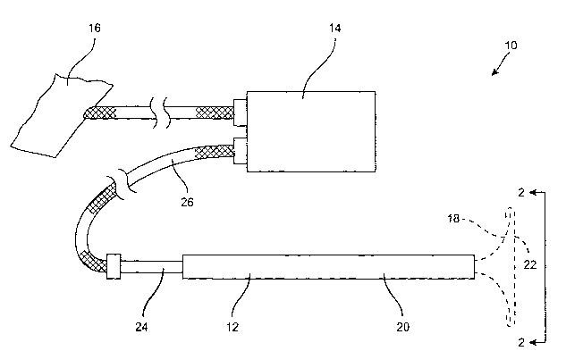
Referring now to Fig. 1, a cardiac electrode deployment device suitable for
performing the methods of the present invention will be described. Cardiac
electrode
deployment device 12 is part of a system 10 which further includes a
controller 14
(typically a defibrillator and/or pacing apparatus as discussed in more detail
below) and
optionally a counter electrode 16. Power supply controller 14 contains the
circuitry
necessary for producing the defibrillation energy, pacing energy, ECG
monitoring, and
19
CA 02400363 2002-08-07
WO 01/58522 PCT/USO1/03810
optionally cardioversion energy which can be delivered or sensed by the
electrode
structure 18 which is shown in its deployed configuration in broken line.
Electrode
structure 18 is preferably shiftable between a low profile conf guration
(where it is drawn
rearwardly) into delivery cannula 20 and the deployed.configuration shown in
broken
line. Most simply, the electrode structure can be formed from a plurality of
resilient
struts having an active electrode surface 22 at their forward ends. The struts
may be
collapsed inwardly by drawing shaft 24 rearwardly relative to the cannula 20,
thus
drawing the electrode structure 18 into the cannula. The electrically
conductive
surface 22 will be connected to the power supply controller 14 through a
connecting
cable 26. Usually, at least one connector will be provided for each
electrically isolated
region within the active electrode area 22, as described in more detail below.
The active electrode surface 22 may have a wide variety of configurations.
Usually, the electrode surface will have a generally circular periphery,
although other
peripheral geometries, such as ovoid, rectangular, triangular, irregular, and
the like, could
also be utilized. The most simple electrode surface geometry is illustrated in
Fig. 2A,
where the surface 22a comprises a single, continuous electrode covering the
entire
circular area of the electrode structure. The electrically conductive surface
may be
formed in any of the ways described above.
The electrode can be formed from a wide variety of conformable,
electrically conductive materials or composites. Usually, the materials will
be flexible
but non-distensible, most usually being formed from non-distensible fabrics.
In one
instance, the fabrics can be metalized, for example by vapor deposition or
plating (either
electro or electroless) of a conductive metal surface over a fabric matrix.
More usually,
however, the conductive fabrics will be formed by weaving at least part of the
fabric from
a metal, preferably in both directions of the weave, but in some cases only in
a single
direction. The metal filaments in the fabric may be disposed at each strand or
fiber,
optionally at every other strand or fiber, usually will be placed at least
once every 100
strands or fibers, more usually at at least every tenth strand. The other
strands or fibers
may be formed from electrically non-conductive materials, such as polyester.
An exemplary fabric is illustrated in Fig. 2AA. The fabric 400 comprises
warp 402 and woof 404 threads which are woven at right angles in a
conventional pattern.
Preferably, at least some of the warp threads 402 and the woof threads 404
will be
electrically conductive, most preferably being a metal, such as gold, silver,
stainless steel,
or other electrically conductive medically acceptable metal. In the exemplary
structure,
CA 02400363 2002-08-07
WO 01/58522 PCT/USO1/03810
the conductive and non-conductive threads will be arranged in an alternating
pattern as
illustrated. Such an alternating construction provides very uniform strength
and electrical
conductivity characteristics. Optionally, the electrically threads will be
metal wires or
filaments which have been mechanically, chemically, electrochemically,
optically, or
otherwise etched or roughened to increase the available surface area to
enhance electrical
contact and conduction with the heart or pericardial surface being contacted.
As a further
option, the metal wires may be twisted, multifilament structures composed of a
number
(two or more) of smaller filaments.
A first alternative electrode configuration 22b is shown in Fig. 2B, where a
pair of semi-circular electrode regions 30 and 32 are spaced-apart on the
exposed surface
of the electrode structure. The two isolated regions are electrically isolated
from each
other and connected independently through the shaft 24 by isolated electrical
connectors.
This way, the electrode regions 30 and 32 can be energized separately or
commonly,
depending on how the power supply controller 14 is arranged. The isolated
electrode
configuration of Fig. 2B is particularly useful for applying to the surface of
the heart so
that the non-electrode region 34 can be placed over the conductive bundle of
the heart. In
this way, the conductive bundle can be protected from direct delivery of
electrical current.
A second alternative configuration comprising a pair of concentric ring
electrodes is shown in Fig. 2C. The concentric ring electrodes could also be
laterally
spaced-apart, as shown in the electrode surface 22d shown in Fig. 2D. In
particular, the
plurality of opposed C-shaped electrode surfaces 40, 42, 44, and 46, may be
formed on
the electrode support.
An electrode surface 22e comprising four pie-shaped isolated electrode
regions 50, 52, 54, and 56, is illustrated in Fig. 2E. A similar electrode
surface 22f
comprising eight pie-shaped isolated electrode regions 62-74 is illustrated in
Fig. 2F. An
additional electrode configuration 22g comprising four pie-shaped electrodes
further
divided into concentric rings, for a total of eight isolated electrode regions
80-94 is
illustrated in Fig. 2g. Finally, a rectilinear array of electrode regions 22h
is illustrated in
Fig. 2H. It will be appreciated that such electrode configurations can easily
be fabricated
using a variety of metal deposition techniques, where an electrically
conductive metal,
such as titanium, stainless steel, silver, gold, and copper, can be deposited,
plated, or
otherwise coated and patterned onto a suitable electrode substrate.
Referring now to Figs. 3-6, an exemplary cardiac electrode deployment
device constructed in accordance with the principles of the present invention
comprises a
21
CA 02400363 2002-08-07
WO 01/58522 PCT/USO1/03810
sleeve 102, a shaft 104 slidably mounted in a central lumen of the sleeve 102,
and a
handle 106 attached to a proximal end of the shaft. The sleeve 102 includes a
positioning
flange 110 near its distal end, typically spaced proximally of the tip 112 of
the device by
an optimum distance, generally as set forth above. A blunt cap 120 is
positioned at the
distal-most end of the device 100 and facilitates entry of the device into the
chest cavity
following tissue dissection, as described in more detail hereinafter.
A flared bell structure 130, as best seen in Figs. 4 and 6, is attached to the
distal end of shaft 104 and assumes a tnunpeted configuration when fully
deployed, as
shown in both of those figures. The flared bell structure 130 comprises a
plurality of
outwardly curving struts 132 (the illustrated embodiment has a total of eight
struts, but
this number could vary). The struts are preferably formed from a resilient
metal, usually
formed from a superelastic alloy, such as nitinol. The use of such resilient
materials will
not always provide the degree of rigidity desired for the forward surface 136
(Fig. 6) of
the flared bell structure. To enhance the rigidity and pushability of the
structure, re-
enforcing beams 138 may be provided. It has been found that the combination of
the
curved struts with reinforcing beam supports provides a useful combination of
stiffness
over the proximal portion of the structure and greater flexibility at the tip
portions.
The blunt cap 120 is mounted on a rod 140 (Fig. 6) having an electrical
connector 142 at its proximal end. When the sleeve is advanced distally over
the flared
bell structure 130, the forward tip of the sleeve will engage the rear of the
end cap 120, as
best seen in Fig. 18. When the sleeve is retracted and the flared bell
structure deployed,
as best seen in Fig. 19, end cap 120 will be free to move axially. In use, the
end cap will
typically be withdrawn proximally into the interior of the structure 130.
The distal tips of the struts 130 are preferably connected by a fabric
electrode structure 150 having an edge Which is folded over and stitched to
hold the cover
in place. The fabric cover may be a light mesh, composed of polyester or the
like, and
will help distribute forces quite evenly over the region of the pericardium
which is
contacted by the flared bell structure.
The fabric electrode structure 150 may have any of the configurations set
forth above in Figs. 2A-2H. The isolated regions) on the electrode surface are
electrically connected through a plurality of conductors (not shown) which
terminate in
the electrical connector 142. The connector 142 will typically include an
array of plug
prongs or receptacles wluch permit inner connection of the connector with a
cable,
22
CA 02400363 2002-08-07
WO 01/58522 PCT/USO1/03810
e.g., cable 26 as shown in Fig. 1. The cable in turn, connects the device to a
suitable
power supply controller.
Referring now to Figs. 7A-7C, the electrode deployment device 100 can be
introduced into a region over the heart and used for direct cardiac massage.
Initially, a
small incision I is made over the heart, preferably on the patient's left side
between the
forth and fifth ribs (R4 and RS). Alternatively, it is possible to introduce
the electrode
deployment device from the right side, particularly if that approach can
improve the angle
for pumping the heart when cardiac compression is employed. After the incision
I is
made, the device 100 is pushed through the incision with the blunt cap 120
protecting the
edge of the device from catching the tissue until the flange 110 engages the
outer chest
wall, as illustrated in Fig. 7B. Optionally, after the incision has been made,
the physician
or other treating personnel may manually dissect the incision which has been
made, as
illustrated in Fig. 7BB. Device 100 may then be pushed through the dissected
incision as
shown in Fig. 7B. At that point, the flared bell structure is still not
deployed. The flared
bell structure 130 is then deployed by advancing shaft 104 until a first
marker 160
approaches the proximal end 162 of the sleeve .102. Once the structure 130 is
fully
deployed, the handle 106 may be manually grasped and the device shaft 104
pumped
through the sleeve 102. This will cause the deployed flared bell structure 130
to engage
the electrode surface against the heart. The structure can then be advanced in
a posterior
direction to compress the heart, generally shown in broken line in Fig. 7C.
Preferably,
the handle will be inclined from 20° to 45° toward the patient's
left in the mid-sagittal
plane while being held generally vertically in the craual-caudal plane. In
this way, the
electrode structure compresses the heart toward the patient's spine to
maximize
compression. Defibrillation energy or pacing is then applied using a power
supply 170
connected via a cable 172 to the electrode structure on the flared bell
structure 130 and
via a cable 174 to a counter electrode 180 which is usually disposed on the
patient's back.
Energy is applied according to the protocols described below. Once
resuscitation has
been completed, the device 100 may be withdrawn by retracting the shaft 104
relative to
sleeve 102 to draw the structure 130 back into the sleeve. The structure 130
will be
sufficiently retracted as soon as the second marker 162 becomes visible out of
the
proximal end of the sleeve. Once the structure 130 is retracted, the device
may be
proximally withdrawn through the incision , measures taken to correct a
pneumothorax,
and the incision closed in a conventional manner. The electrode deployment
device 100
is intended for "monopolar" operation. That is, the electrode structure on the
device 100
23
CA 02400363 2002-08-07
WO 01/58522 PCT/USO1/03810
will be connected to one pole of an associated defibrillator, pacing device,
or the like.
The other pole will be connected to an external electrode engaged against the
patient's
skin. It will also be possible to construct an electrode deployment device
intended for
"bipolar" operation, as described in detail in connection with Fig. 7D below.
An exemplary defibrillator 400 for use in the systems and methods of the
present invention is shown in Fig. 8. The defibrillator 400 will usually be
designed to be
portable for surface mounting, hook suspension, or other forms of placement at
the site of
use, which will typically be in a hospital or at an emergency site in the
field. The
defibrillator will preferably have a clam shell structure with a fold-up
display 402,
typically a back lit LCD display or other low energy consumption display, and
a
base 404. The display 402 is connected to the base by a hinge 406 which
permits opening
and closing of the display for use and storage, respectively. The hinge 406
also permits
repositioning of the display 402 relative to the base for optimal viewing.
Optionally, the
hinge can be provided with detents to hold the display at a plurality of
discrete angles
relative to the base. The defibrillator 400 will typically be mufti-
functional, and include,
in addition to defibrillation capability, at least pacing capability and
usually EKG/ECG
monitoring capability. Other optional features will be discussed in more
detail below.
The defibrillator 400 will be configured to permit attachment of at least a
cardiac
electrode deployment device, such as device 12 described in detail above. The
electrode
deployment device 12 will be connected via a cable 406 which is attached to
the
defibrillator to permit the delivery of defibrillation energy through the
electrode
deployment device. Usually, the connection will be made by a removable
connector 408
which plugs into an appropriate receptacle 410 on the base 404 of the
defibrillator 400.
Similarly, a counter electrode 412 (shown in broken line) will be connected to
the
defibrillator 400 via a cable 414. While the attachment could be permanent, it
will
usually be removable using a connector 416 which plugs into a receptacle 418
on the
base 404. The connector will preferably be waterproof. The defibrillator will
preferably
be battery-powered, with a removable battery 420 being insertable into an
appropriate slot
or other receptacle (not shown) in the base 404. The batteries may be
rechargeable and/or
replaceable. A particular advantage of the systems of the present invention is
that the
batteries may be made much smaller (with a corresponding lower weight) because
of the
reduced power requirements of percutaneous defibrillation. Usually, the
defibrillator 400
will also include a port 422 on the base or elsewhere for receiving a plug-in
EKG/ECG
pad 424. The ECG/EKG pad may be a conventional pad of the type used with
portable,
24
CA 02400363 2002-08-07
WO 01/58522 PCT/USO1/03810
external defibrillators. The base 404 will further include conventional I/O
devices,
usually located on the upper surface which is protected by the pull-down
display 402
when the device is closed. The I/O devices may comprise keyboards, knobs,
dials, cursor
arrows, or the like. The devices may have dedicated functions, or may be user
definable
depending on the precise prograrmning wluch is employed. Finally, the
defibrillator 400
may have ports for external connections to a variety of external devices,
including
computers, conventional EKG/ECG monitors, recording devices such as strip
chart
recorders, external power sources, battery charges, and the like. For the
transmission of
digital data, the ports may be serial, parallel, SCSI, USB, infrared,
radiofrequency, or
modem connections, i.e., the device would include an internal modem.
Optionally, the defibrillator 400 will also include speakers or other devices
for providing audible information and alerts. In some instances, the
defibrillator may
include speech synthesis capability to provide verbal warnings or instructions
to the user
during performance of a protocol. Additionally, or alternatively, other alarm
features,
1 S such as lights, buzzers, and the like, may be provided on the device.
Further optionally,
the defibrillator 400 may include digital and/or analog recording capability
for recording
the EKG/ECG waveforms, the timing and level of energy delivery, pumping
parameters
(such as timing, force, etc.), voice recordings made using a suitable
microphone built into
the defibrillator or elsewhere, video signals produced by a camera on board
the treatment
electrode or compression device, ultrasound signals generated by a transducer
on board
the electrode or compression device, etc.
While described above as a defibrillator, it will be appreciated that the
systems and methods of the present invention could be used for pacing, EKGIECG
monitoring, or other electrical therapy or monitoring of the heart without
defibrillation.
For example, as described in more detail below, provision of the ECG/EKG
capability
together with pacing capability will permit both monitoring and pacing of the
heart to be
performed in conjunction with internal heart compression or cardiac massage.
For
patients in asystole, or suffering from PEA, defibrillation will not normally
be an
effective therapy. In asystole, internal pacing combined with direct cardiac
massage may
be of great benefit. By further providing control circuitry within the "power
supply" 400,
coordination and synchronization of the cardiac compression with the pacing
signal can
be substantially enhanced. In some instances, it will be possible to directly
trigger the
pacing signal to match the manual cardiac compression rhythm, i.e., a motion
sensor,
force sensor, or limit switch within the system could trigger the pacing
signal at the
CA 02400363 2002-08-07
WO 01/58522 PCT/USO1/03810
appropriate point during each heart compression cycle. Usually, pacing is
applied during
the end of the diastole or point of minimum cardiac compression.
Alternatively, the
pacing signal could be provided in a predetermined, usually constant pattern,
with a
visual or audible signal provided to the user to manually coordinate the
cardiac
compressions with the pacing signal, i.e., the user would pace in rhythm with
the light
(e.g., LCD or LED) or sound which matches the pacing rhythm.
Pacing energy may be provided through a singular electrode, such as that
shown in Fig. 2A, or through an array of electrodes, such as those shown in
Figs. 2B
through 2H. Multiple electrodes of the array would be connected to a
controller and fired
in a sequence selected to mimic the contractions of a naturally beating heart.
For
example, the atria would be paced ahead of the ventricles by approximately 0.1
to 0.15
seconds. Device orientation would be important and this could be done by
aligning an
external part of the device (e.g., handle) with the direction of the head or
feet or other
portion of the patient's anatomy. It could also be done automatically by the
device,
which would select ventricular and atrial electrodes from an array of
electrodes.
Refernng now to Fig. 9, a functional block diagram of exemplary circuitry
for the defibrillator 400 is provided. A defibrillator 400 will be controlled
by a
microcomputer 430 which is interfaced through the user I/O capability
described
previously. The microcomputer will be interfaced with suitable memory and have
embedded and/or programmable instructions provided in a conventional manner.
It will
be appreciated that specific logical functions can be implemented either in
the
programming of the microcomputer or in digital or analog circuitry distributed
in various
discrete devices within the defibrillator. For example, the signals provided
by the
EKG/ECG electrodes input through receptacle 422 may be processed in whole or
in part
by dedicated digital or analog circuitry which is well-known and described in
the patent
and technical literature. Alternatively, at least part of the analysis and
evaluation may be
performed by and programmed into the microcomputer. In any event, the
microcomputer
will either receive or generate data representing the patient's EKG/ECG, and
that data can
be used for display and/or active control of other aspects of the system,
including in
particular pacing of the patient. Thus, discrete digital or analog circuitry
432 may be
provided to at least partially process the EKG/ECG signal. Data transmission
within the
defibrillator 400 will be provided by a conventional system bus 440, which
communicates
with, for example, a computer interface 442, having a port 444 on the base 404
(not
shown). The pacing information generated by the microcomputer 430 is also
delivered to
26
CA 02400363 2002-08-07
WO 01/58522 PCT/USO1/03810
a discrete timer 446 which controls conventional pacing output circuitry 448
Which feeds
directly to the pacing electrodes through the receptacle 410. Similarly,
defibrillation
energy levels and timing will be set by the system microcomputer 430 with the
set points
delivered through the bus to a suitable high voltage DC-DC converter 450. The
converter
receives energy directly from the battery and delivers the high-voltage energy
to
capacitors 452. Because of the low energy requirements of the percutaneous
defibrillation, the capacitors may be significantly smaller than those
utilized in
conventional external defibrillation. Finally, the capacitors will feed into
generally
conventional (but potentially smaller) defibrillation output switches 454
which are
connected to the ports 410 and 418. It should be noted that the port 410 will
service both
the pacing electrodes and the defibrillation electrodes. In such instances,
the
connector 408 which plugs into the receptacle 410 can be configured to mate
with the
appropriate pins or other coimection elements within the port 410. In this
way, the pacing
energy will be delivered to pacing electrodes wlule defibrillation energy will
be delivered
to the defibrillation electrodes and the wrong form of energy cannot be
accidentally
delivered to the patient.
In addition to the defibrillation, pacing, and EKG/ECG capabilities, the
defibrillator 400 may optionally include an input 460 for a capnograph sensor
to measure
carbon dioxide in patient ventilation. The capnograph sensor may be
conventional and
located for example, in a breathing tube used to ventilate the patient.
Additionally, an
input port 462 may be provided to be connected to a force sensor located in
the electrode
or compression surface deployment device. Alternatively, the force information
could be
fed back through the same cable 406 into port 410. In either case, the system
will then be
able to alert the user if excessive or inadequate force is being applied to
the heart. In
contrast to conventional CPR, direct cardiac massage will use much lower
compression
forces, typically below 15 Ib, and preferably between 3 1b to 12 1b.
Application of the
much higher forces which are associated with CPR can cause significant damage
to the
heart.
Refernng now to Fig. 10, a hand-held defibrillation device 500 comprises
a handle assembly 502, a shaft 504, and a deployable electrode structure 506.
Discrete
and/or continuous electrode surfaces) 507 are provided on electrode structure
506. The
shaft 504 and deployable electrode structure 506 may generally be as described
above,
but in some cases a portion of the shaft 504 may be removable via a disconnect
508. By
having the distal portions of the shaft and deployable electrode structure
removable and
27
CA 02400363 2002-08-07
WO 01/58522 PCT/USO1/03810
disposable, the handle 502 and proximal portions of the shaft 504 may be
reusable. Of
course, the entire shaft 504 may disconnect from the handle at a point much
higher up in
the device 500 as well.
The hand-held defibrillation device 500 includes all power and circuitry
components for the defibrillation system (and optionally pacing, EI~G/ECG, and
other
components shown in Fig. 9) within or attached externally to the handle
assembly 502. In
the illustrated embodiment, an electronic module 512 is located on one side of
the handle,
while the battery 514 and defibrillation capacitors 516 are located on another
side of the
handle. A slot 518 which defines the handle grip is located in the middle of
the handle.
An external port or connector 520 is provided for connecting cable 522 for an
external
ECG pad 524. Optionally, other ports or comzectors (not shown) could be
provided for a
capnograph sensor, an external computer, or the like.
The hand-held defibrillator 500 will preferably have the defibrillation
"shock" button 530 on its upper surface to facilitate triggering of the
defibrillation shock
while the user is compressing the heart, typically using a single hand.
Provision of a
shock button on the other electrode deployment devices illustrated herein,
such as
device 12 (Fig. 1), device 100 (Fig. 3), etc., will also preferably include a
shock button
where the user can depress the button while gripping the handle and
compressing or
otherwise manipulating the device on the patient. It is an advantage for the
user to be
able to both compress the heart with the device and to initiate a
defibrillation shock using
a single hand, most preferably with the other hand being held away from the
patient to
avoid shocking the user inadvertently. Optionally, the hand-held defibrillator
500 may
further include a safety interlock feature (not shown) which must be
disengaged prior to
actuation of the shock button 530. The safety interlock can include a second
button
which must be simultaneously actuated together with the "shock" button or can
include a
cover over the shock button which must be moved before actuation. Other
conventional
safety interlocks would also be useful.
A first exemplary protocol for utilizing the cardiac electrode deployment
device to resuscitate a patient in cardiac arrest is shown in Fig. 11A. After
the device is
introduced and deployed, as generally shown in Fig. 7A-7C, the heart may be
compressed. Optionally, the electrically conductive surface of the bell
structure 130 can
be coated with an electrically conductive gel prior to introduction. The gel
helps establish
electrical contact and reduces the impedance between the electrically
conductive surface
and the heart. It will be necessary, however, when it is desired to retain
electrically
28
CA 02400363 2002-08-07
WO 01/58522 PCT/USO1/03810
isolated regions, to make sure that the conductive gel does not short adjacent
regions of
the electrode structure. Optionally, the electrode structure may be pre-coated
with
hydrogel in order to minimize the amount of hydrogel used and to reduce the
risk of
shorting the isolated electrode structures. Prior to, during, or immediately
following such
compression, the electrode structure on the device may be used to monitor the
patient
EKG/ECG. If the EKG/ECG is acceptable, the device can be used to perform
compression until the situation is resolved, hopefully with the patient being
resuscitated.
If the observed EKG/ECG is not acceptable, the electrode structure can be used
to apply
defibrillation energy to the heart. Usually, defibrillation energy will be
applied in a single
step (although the step may be divided into a series of discreet,
progressively more
energetic applications of energy over a very short time period, as described
above).
Direct contact of the electrode structure with the heart allows use of
relatively low
defibrillation energies as discussed above. After the single application of
energy has been
completed, heart function will again be assessed by EKG/ECG. If the initial
defibrillation
has been successful, the treatment can frequently be terminated or continued
with
compression alone, or compression plus pacing, until the patient is
resuscitated. If the
initial defibrillation has been unsuccessful, i.e., acceptable EKG/ECG has not
been
achieved, the patient may again be defibrillated following direct cardiac
massage. Third
and subsequent defibrillation steps can further be provided until restoration
of an
acceptable EKG/ECG is achieved. If defibrillation continues to be
unsuccessful, the
patient can continue to be compressed until the situation is resolved, further
surgical or
other interventions (e.g., cardiopulmonary bypass) are initiated, or there is
no reason to
continue cardiac compression.
Use of a modified device 200 for resuscitating a patient is illustrated in
Fig. 7D. The device 200 comprises a sleeve 202 and flared bell structure 230,
as
generally described above for the device 100. The device 200 differs
principally in that it
includes an integral second electrode 240 which serves as a counter electrode
in
performing defibrillation according to the present invention. The electrode
240 is
expansible from a low profile configuration to an expanded configuration so
that it can
engage the interior thoracic wall, e.g., an interior surface of the rib cage,
when the
device 200 is deployed. The electrode 240 will usually be attached to the
sleeve 202 so
that the electrode 240 remains generally stationary against the interior
thoracic wall as the
flared bell structure 230 (carrying the primary electrode structure) is
reciprocated to
compress the heart. Defibrillation current can be applied by any of the
protocols
29
CA 02400363 2002-08-07
WO 01/58522 PCT/USO1/03810
described herein, and the current wall will generally follow the flux lines
250 shown in
Fig. 7D. Cables 270 at 274 connect the power supply 280 to the primary and
counter
electrodes on the device 200.
Refernng now to Fig. 11B, a second exemplary protocol fox performing
the methods of the present invention will be described. After a cardiac
compression/defibrillation/pacing device is introduced and deployed, the
patient's
EKG/ECG will be monitored. Usually, at least some of the electrodes on the
device
surface which are in contact with the heart will be used for monitoring.
Optionally, or
alternatively, chest mounted electrodes) can be used for EKG/ECG monitoring.
For
example, a single external EKG/ECG electrode pad structure can be used, where
the
electrode structure includes multiple separate electrode regions which are
isolated from
each other and which are used to obtain multiple EKG/ECG signals without the
need to
use more than one separate electrode assembly. Further optionally, the nature
and quality
of ventricular fibrillation can be assessed using Fourier pattern analysis to
determine the
frequency spectrum of the waveform. Components of the waveform that can be
analyzed
include the voltage amplitude, frequency of fibrillation, lack of diastolic
plateau, and the
lilce.
Based on the nature of the patient's EKG/ECG, a preferred course of
treatment can be selected. If the patient is determined to be in asystole,
i.e., no cardiac
sinus rhythm, then the patient will be treated by compression optionally with
pacing.
Compression and/or pacing can be continued until a normal cardiac rhythm is
reestablished or it is determined that the patient cannot be resuscitated. If
the patient is
determined to be in fibrillation, defibrillation energy will be applied to the
heart as
described above in connection with earlier embodiments. Compression can be
performed
simultaneously and/or after the heart has been defibrillated. If the patient
is determined to
be in tachycardia, then the device will be used to apply pacing energy
directly to the
heart. Optionally, the heart can be compressed simultaneously and more
preferably
synchronously, with the application of pacing energy. Finally, if the patient
is determined
to be in PEA, a preferred course of treatment will be compression only.
Refernng now to Fig. 11C, in cases where the cardiac massage device is
introduced without any form of imaging, it will be desirable to have a method
fox
confirming proper placement of the deployable electrode structure over the
heart. A
preferred method for confirming placement of the electrode structure is to use
an
electrode structure having at least two, preferably three, and optionally a
greater number
CA 02400363 2002-08-07
WO 01/58522 PCT/USO1/03810
of isolated electrode regions on its surface. Two or more of such isolated
electrode
regions will be used to separately monitor EKG/ECG from the heart. It will be
appreciated that if the electrode region is not in contact with the heart, the
detection of
EKG/ECG will be greatly diminished or absent. Thus, by monitoring ECG from
each of
the isolated electrode regions, and determining whether ECG is present, it can
be
determined whether all of these regions are in contact with the heart. Thus,
after initially
placing the deployed electrode structure on the heart, the device can be moved
until a
maximum number of the isolated electrode regions display and EKG/ECG signal.
Alternatively, collective signals from the various regions can be observed,
and the device
can be repositioned until the observed signal is maximized. After the expanded
structure
is properly placed, the structure can be used compress the heart generally as
described
above. This placement method, of course, will not be effective with patients
in asystole
since there will be no waveform to observe.
The defibrillators and other cardiac electrode deployment structures of the
present invention may further comprise imaging capability which permits
visualization of
the thoracic cavity and heart during deployment of the electrode structure. In
particular,
by providing a direct imaging capability on or near the electrode structure,
the practitioner
can guide the electrode structure to the desired target location over the
pericardium or
heart by visualizing the region in real time during the deployment protocol.
A cardiac electrode deployment tool 600 having a fiberoptic or rod lens
viewing scope incorporated therein is illustrated in Figs. 13 and 13A. The
electrode
deployment tool 600 includes a sleeve 602, a shaft 604, and a handle 606, all
generally
the same as those described in connection with earlier embodiments. An
expansible
electrode structure 608 is positioned at a distal end of the device 600 and is
deployable by
moving the handle 606 relative to the sleeve 602. The cardiac electrode
deployment
tool 600 differs from prior embodiments in that it includes an optical imaging
fiber or
bundle 610 which extends through the sleeve and terminates in a viewing tip or
lens 612.
Illumination bundles 614 are also provided in the sleeve 602, and both the
imaging fiber
and illumination bundles are connected to a video display 618 by a connecting
cable 620.
The viewing display and electronics required for operating both the
illumination and
imaging components of the system are well-known in the endoscopic arts. The
viewing
display 618 may be incorporated in a defibrillator 622 which may be connected
to the
electrode deployment tool 600 by a second cable 624. A defibrillator 622 may
generally
have the form described earlier in connection with the defibrillator 400. The
viewing tip
31
CA 02400363 2002-08-07
WO 01/58522 PCT/USO1/03810
or lens 612 will be configured within the sleeve 602 so that it can view in a
forward or
distal direction from the sleeve so that, when the electrode structure 608 is
retracted, it
can see clearly forwardly of the sleeve. Alternatively, when the electrode
structure 608 is
deployed, it will be able to view the electrode relative to the heart H.
Referring now to Fig. 14, an additional cardiac electrode deployment
tool 700 comprising sleeve 702, as shaft 704, and a handle 706, is
illustrated. The
tool 700 further comprises a deployable electrode structure 708 which may be
retracted
and deployed in a manner analogous with previously described embodiments of
the
deployment tools herein. Cardiac electrode deployment tool 700 is further
provided with
an ultrasonic imaging capability. In particular, an ultrasonic transducer 710
is provided in
a distal tip element 712, which may be a blunt actuator used to assist in
introducing the
device via a blunt dissection. The tip element 712 will be configured so that
it leads a
tool 700 as .it is introduced distally into the thoracic cavity through an
intercostal access
route, as described previously. The ultrasonic transducer 710 may be connected
via an
appropriate electrical cable which passes through shaft 704 and via cable 720
to an
ultrasonic image display screen 722. The ultrasonic display screen 722 is
shown separate
from the defibrillator, but could be incorporated therein if desired. The
defibrillator may
be connected to the device 700 through a cable 724 which in turn is connected
to an
external defibrillator (not shown).
The previously described embodiments have generally shown the
defibrillation, pacing, EI~G/ECG, or other electrodes being positioned on the
deployable
electrode structure. Usually, the deployable electrode structure is also
suitable for cardiac
compression. As shown in Fig. 15, however, the defibrillation or other cardiac
electrodes
of the present invention could be incorporated into other structure which is
deployed
using the access probes of the present invention. In particular, balloons or
other
expansible electrode support structures may be deployed together with the
cardiac
compression structure, where the cardiac compression structure may or may not
include
electrodes) on its cardiac contact surface. For example, a device 800 may
include a
cardiac compression structure 802 (optionally having electrodes thereon), a
first electrode
balloon 804, and a second electrode balloon 806. The cardiac compression
structure 802,
as well as the electrode balloons 804 and 806, are deployed through a sleeve
810 and a
shaft 812, generally as described above in connection with prior electrode
deployment
structures. The balloons 804 and 806 are inflated in any conventional manner,
typically
using an inflation syringe 814 which may be coupled to the balloons through
the
32
CA 02400363 2002-08-07
WO 01/58522 PCT/USO1/03810
sleeve 810. Electrodes on the balloon, as well as the optional electrode on
compression
stnzcture 802 will be connected to a defibrillator 830 which may optionally
include
pacing, EKG/ECG, or other capabilities. By including at least two laterally
spaced-apart
electrodes on separate deployment structures, such as balloons 804 and 806,
the electrode
contact areas on the heart can be more widely spaced apart then if the
electrodes are
present on a single deployment structure, such as the cardiac compression
structure 802.
Preferably, at least a first electrode structure will contact the heart near
the apex while an
at least second electrode will contact the heart near the base. In this way,
current flow for
defibrillation can run along the axis of the heart. Other more complex
patterns may also
be applied, particularly for defibrillation.
In all of the above embodiments, it will in some cases be desirable to
provide a vacuum capability on the cardiac contact electrode structure. In
order for
proper defibrillation, pacing, monitoring, or other electrical procedures to
be conducted,
good electrical contact between the electrode structures and the heart is
necessary. While
the use of electrically conductive gels will improve electrical contact, it is
also desirable
to enhance contact by applying or drawing a vacuum between the electrode
structure and
the heart. Particularly in the case of the expansible electrode structures
which may
optionally be used for cardiac compression, it will be desirable to maintain
an adherence
between the structure and the heart at all times during the compression cycle
(including
withdrawn diastole and filling). By applying a vacuum through the deployable
electrode
structure, such contact can be achieved.
Referring now to Fig. 16, a kit 300 according to the present invention
comprises a cardiac electrode deployment tool, such as device 100 described in
detail
previously, in combination with instructions for use IFU setting forth any of
the methods
described above. Usually, the device and instructions for use will be combined
in a
suitable package P that can be in the form of any conventional medical device
packaging,
such as a tray, tube, box, pouch, or the like. The instructions for use will
usually be
provided on a separate package insert, but could also be printed directly on
all or a
portion of the packaging P. Additional components, such as a counter
electrode, could
also be provided as part of the kit.
While the above is a complete description of the preferred embodiments of
the invention, various alternatives, modifications, and equivalents may be
used.
Therefore, the above description should not be taken as limiting the scope of
the
invention which is defined by the appended claims.
33