Note: Descriptions are shown in the official language in which they were submitted.
CA 02400775 2002-08-28
Electrolyzes
Field of the Invention
The present invention relates to an electrolyzes and, in particular, an
electrolyzes for
producing hydrogen gas from water.
Background of the Invention
Electrolyzers for producing hydrogen gas from water, generally in the form of
an
electrolyte solution, are known. Such electrolyzers are particularly useful
for
producing hydrogen and oxygen gases in a vehicle, the gases being used to
supplement and enhance the fuel supply to the vehicle's engine.
Previous electrolyzers for on-board vehicle use had various drawbacks. The
electrolyzers were archaic, large and heavy, utilizing technology that had
been in
place for a number of years such as stainless steel plates and open
containers. In
addition, the electrolyte often became polluted by metal ions that came off
the plates
and often ran low. These issues had safety consequences and resulted in a lack
of
efficiency and reliability in the unit.
Many previous cells generated hydrogen gas and oxygen together without
separating
the gases. Thus, since these gases together are extremely explosive, many
safety
components had to be incorporated in any electrolyzes system. This increased
complexity of many previous systems and, thereby, their cost and chance of
failure.
Summary of the Invention
An electrolysis cell has been invented that allows an increase in power
density, and a
reduction in size and weight over previous electrolyzes cells. Hydrogen and
oxygen,
although both generated in the cell, are maintained separate so that concerns
over
explosion are reduced or eliminated. An electrolyzes unit can include one or
more of
the electrolysis cells.
CA 02400775 2002-08-28
In accordance with one aspect of the present invention, there is provided an
electrolysis ccll for producing hydrogen and oxygen from a concentrated liquid
electrolyte, the cell comprising: a housing, a plurality of porous cathode
plates, a
plurality of porous anode plates disposed between the cathode plates, a
hydrogen gas
conduit in fluid flow communication between the cathode plates and a hydrogen
gas
outlet port on the housing; an oxygen gas conduit in fluid flow communication
between the anode plates and an oxygen gas outlet port on the housing, an
electrolyte
inlet and an electrolyte outlet, the electrolyte inlet and the electrolyte
outlet arranged
such that electrolyte flows through the anode plates and the cathode plates
and a
separator disposed between each adjacent anode plate and cathode plate, a
separator
disposed adjacent each of the clcctrofytc inlet and the electrolyte outlet,
the separators
being selected to be permeable to electrolyte and impermeable to hydrogen gas
and
oxygen gas.
In accordance with another aspect of the present invention, there is provided
an
electrolyzer unit for producing hydrogen and oxygen from a concentrated liquid
electrolyte, the unit comprising: a housing; two electrolysis cells within the
housing,
each electrolysis cell including an inner chamber and disposed therein a
plurality of
porous cathode plates, a plurality of porous anode plates, the porous cathode
plates
alternating between the anode plates and a separator disposed between each
adjacent
anode plate and cathode plate, the separators being selected to be permeable
to
electrolyte and impermeable to hydrogen gas and oxygen gas bubbles; a hydrogen
gas
conduit in fluid flow communication with the cathode plates and a hydrogen gas
outlet port on the housing; an oxygen gas conduit in fluid flow communication
with
the anode plates and an oxygen gas outlet port on the housing, a secondary
electrolyte
inlet and a secondary electrolyte outlet, the secondary electrolyte inlet and
the
secondary electrolyte outlet arranged such that electrolyte flows through the
anode
plates and the cathode plates, a separator disposed adjacent each of the
secondary
electrolyte inlet and the secondary electrolyte outlet; a main electrolyte
inlet conduit
to supply electrolyte to the cells and extending between the secondary
electrolyte
inlets of the two electrolysis cells; and a main electrolyte outlet conduit
through which
electrolyte is evacuated from the cells, the main electrolyte outlet conduit
extending
between the secondary electrolyte outlets of the two cells; the main
electrolyte inlet
conduit and the secondary electrolyte inlets together being formed to maintain
CA 02400775 2002-08-28
3
galvanic separation of at least 95% between the two cells; and the main
electrolyte
outlet conduit and the secondary electrolyte outlets together being formed to
maintain
galvanic separation of at least 95% between the two cells.
In accordance with another broad aspect of the present invention there is
provided an
electrolyzer unit for producing hydrogen and oxygen from a concentrated liquid
electrolyte, the unit comprising: a housing; a first electrolysis cell within
the housing
and a second electrolysis cell within the housing, each electrolysis cell
including a
plurality of porous cathode plates, a plurality of porous anode plates
disposed between
the cathode plates, a hydrogen gas conduit in fluid flow communication with
the
cathode plates and a hydrogen gas outlet port on the housing; an oxygen gas
conduit
in fluid flow communication with the anode plates and an oxygen gas outlet
port on
the housing, a first and a second electrolyte inlet and a first and a second
electrolyte
outlet, the electrolyte inlets and the electrolyte outlets arranged such that
electrolyte
flows through the anode plates and the cathode plates and a separator disposed
between each adjacent anode plate and cathode plate, a separator disposed
adjacent
each of the electrolyte inlets and the electrolyte outlets, the separators
being selected
to be permeable to electrolyte and impermeable to hydrogen gas and oxygen gas
bubbles; an electrolyte inlet conduit to supply electrolyte to the cells and
extending
between the electrolyte inlets of the first and the second electrolysis cells;
an
electrolyte outlet conduit through which electrolyte is evacuated from the
cells, the
electrolyte outlet conduit extending between the electrolyte outlets of the
first and the
second electrolysis cells; and an electrolyte diffusion assembly positioned
between the
first and the second cells and forming a wall therebetween, the electrolyte
diffusion
assembly defining the first electrolyte inlet and the first electrolyte outlet
of the first
electrolysis cell and the second electrolyte inlet and the second electrolyte
outlet of
the second electrolysis cell.
In accordance with another broad aspect of the present invention, there is
provided an
electrode for use in an electrolysis cell, the electrode comprising: a porous
conductor
having an outer surface, an active layer material on the outer surface of the
porous
conductor, a catalyst dispersed within the active layer material, and a
contact for
electrical connection to a power source, the contact molded into contact with
the
porous conductor.
CA 02400775 2002-08-28
4
Brief Description of the Drawings
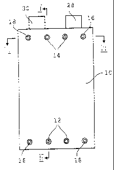
Figure 1 is an end elevation of an electrolysis cell according to the present
invention.
Figure 2 is a schematic section along line II - II of Figure 1.
Figure 3 is a schematic section along line III - III of Figure I.
Figure 4 is a schematic section through an electrolyzer unit according to the
present
invention, the section being along the electrolyte inlet conduits.
Figure Sa is a plan view of an anode according to the present invention.
Figure Sb is a sectional vices along line V1- V1 of Figure 5.
Figure 6a is a perspective view of a folded electrode useful in the present
invention.
Figure 6b is a side elevation of a folded electrode useful in the present
invention.
Figure 7 is a schematic sectional view through a cell showing electrolyte
flow.
Figure 8 is a sectional view through an electrolyzes with the components
within the
cell removed.
Figure 9 is an exploded view of an electrolyte distribution assembly useful in
the
presentinvention.
Figure 10 is a schematic view of an electrolyzes unit showing the electrical
connections.
Figure I 1 is a schematic view of the electrolysis unit in a vehicle.
Detailed Description of the Present Invention
Referring to Figures 1 to 3 an electrolysis cell according to the present
invention is
shown. The cell contains a plurality of anodes 4 and cathodes 6 and operates
using a
concentrated liquid electrolyte such as 3 to 7 molar potassium hydroxide. The
use of
highly concentrated electrolyte allows the cell to operate in low temperatures
without
freezing. Each adjacent anode and cathode has therebetween an electrolyte-
permeable, gas-impermeable separator 8. The electrodes and separators are
formed as
CA 02400775 2002-08-28
S
thin plates and arranged in a stack. A separator 8 is also disposed at each
end of the
stack. The electrolysis cell is illustrated schematically in Figures 2 and 3,
in that the
thickness of each electrode and each separator is overemphasized and out of
proportion. Generally, the electrodes and separators are each less than lmm
thick,
while being much larger in plan (i.e. for example 10 to 20cm wide and 20 to 40
cm
long). Thus, the cell is actually much thinner and more compact than that
shown in
the drawings.
An outer housing 10 is disposed about the stack of anodes 4, cathodes 6 and
separators 8. The housing defines an inner chamber 11 in which the anodes,
cathodes
and separators are disposed. The housing is arranged closely about the
electrodes and
separators. In particular, in the illustrated embodiment, the cell is formed
such that
the electrodes and separators are embedded in the material of the housing.
This is
achieved by arranging the electrodes and separators in a mold and injecting
the
housing material in liquid form about the arranged parts and allowing the
housing to
set, as will be more fully described hereinafter.
Housing 10 has a plurality of inlet and outlet ports extending therethrough.
In
particular, the housing includes inlet ports 12 for electrolyte, outlet ports
14 for
electrolyte, outlet ports 16 for generated hydrogen and outlet ports 18 for
generated
oxygen. Ports 12 to 18 can be tapped or otherwise prepared to receive
connectors 19
for connection to fluid lines.
Ports 12, 14, 1G and 18 are in fluid flow communication with conduits
extending
through the cell. In particular, ports 16 and 18 are in fluid flow
communication with
hydrogen conduit 20 and oxygen conduit 22, respectively, and ports 12 and 14
are in
communication with electrolyte inlet and outlet conduits 24, 26, respectively.
Each of
the electrolyte conduits 24, 26 have openings 24a, 26a to inner chamber 11
where the
electrodes and separators are disposed. An electrolyte distribution assembly
27 is
disposed at each end of the stack between the conduit openings 24a, 26a and
the end
separators 8. Electrolyte distribution assembly 27 includes a plate 27a that
forms the
ends of conduits 24, 26 and defines openings 24a, 26a and a diffusing member
70.
An electrical contact 28, 30 is connected to each anode and cathode,
respectively.
They extend out through the housing to be accessible for connection to a power
CA 02400775 2002-08-28
6
source. Preferably, all of the anode contacts 28 are disposed in line on the
housing
and all of the cathode contacts 30 are disposed in line on the housing and out
of line
with anode contacts 28. This facilitates connection to the power source. To
further
facilitate connection to the power supply all contacts of the same type can be
molded
together to form one unitary contact 31 for alt cathodes of the cell and
another unitary
contact for all anodes. Thus each cell will have only two terminals to connect
supply
current to eight plates.
During operation of the cell, electrolyte flows through conduits 24, through
to inner
chamber 11, outlet conduits 26 and out of the cell. The electrolyte flow
parameters
and specifically the pressure of inlet fluid and the pressure of outlet fluid
and the
relative positioning of the inlets and outlets of the cell are selected such
that at least
some of the electrolyte flows through the planes of the electrodes and
separators
before passing into outlet conduits 26. While two of each electrolyte conduit
24, 26
are shown in the cell, any number of electrolyte inlets and outlets can be
used. If one
of each inlet and outlet conduit is used, they should be positioned at
opposite ends of
the cell such that electrolyte must flow though the electrodes when passing
from the
inlet to the outlet.
Power is applied to contacts 28 and contacts 30 are connected to ground. The
transfer
of electrical energy through the cell creates oxygen at the anodes 4 and
hydrogen at
the cathodes 6. The generated gases cannot mix because of the presence of gas-
impermeable separators 8 between each adjacent anode and cathode. Conduit 20
is
only in fluid flow communication with the cathodes 6 and conduit 22 is only in
fluid
flow communication with anodes 4. Thus, any gases evolved on the electrodes
flow
through one of conduits 20, 22 without mixing.
The cell can be manufactured in various ways. However, in one preferred
manufacturing process the electrodes and separators are formed with generally
similar
widths and lengths and the electrodes and separators are stacked in a selected
and
aligned arrangement with their planes substantially parallel. The stack is
then placed
in a mould and while being maintained in this stacked configuration in the
mould, a
liquid form of the housing material is injected about the stack such that,
when the
liquid solidifies, the stack is cast within the housing material. In
particular, the edges
of any porous member such as the electrode and diffuser are infiltrated with
housing
CA 02400775 2002-08-28
7
material while the centers of these members remain open and untouched by
housing
material.
The housing material surrounds the stack and infiltrates the edges of any
porous
members such as the anodes and cathodes. Thus, the inner chamber will actually
be
formed inwardly of the edges of the individual plate members, as shown. To
prevent
the housing material from infiltrating beyond desired limits, sealants can be
applied
around the edges of the porous members or the edges can be formed to inhibit
infiltration thereto. This will be further discussed with respect to Figures
5a and 5b.
In addition, the elements of the electrolyzer are pressed together and present
mechanical barriers of compatible material allowing the liquid to access and
fill only
desired volumes.
The conduits 20 to 2G can be formed in various ways. In one embodiment,
conduits
20 and 22 are made by forming apertures on the electrodes, separators and
electrode
distribution plates and aligning these apertures when arranging the stack. The
liquid
housing material is then injected about the stack and is selected to
infiltrate about the
formed apertures. When the housing material sets, it forms a solid barrier to
isolate
the selected apertures from the inner chamber of the cell. This will be
described in
more detail, hereinafter.
For safety, it is useful not to have gases generated in areas where the gases
will not be
passed to a gas conduit. Of course, if gases are generated between a pair of
separators, the gases will be forced to pass into a gas conduit, since bubbles
cannot
pass through a separator. To avoid having gases generated outside of the
separators
such as in the electrolyte conduits, the potential difference between any
exposed
conductive parts such as, for example, pump components, electrodes or
fittings, in the
electrolyte path outside of the separators should be no greater than 1.2 volts
and
preferably no greater than 1.4 volts. Potential differences greater than 1.2
volts will
generally occur when an anode or both an anode and a cathode are exposed in a
conduit. Thus, conduits 24, 2G should have no reactive electrode surfaces
exposed
therein. Thus, it is preferred that the manufacture process ensures that the
reactive
electrode surfaces are recessed back from the exposed surfaces of conduits 24,
2G
outside of the separators.
CA 02400775 2002-08-28
The mould is selected such that portions of the contacts 28, 30 extend out
from the
housing and are accessible for connection to the power source.
The housing material is selected to be thermally stable in conditions ranging
from -45
to +100°C, and resistant to the chemical and electrical conditions
present in the cell.
The housing material must also be useful for molding in liquid form. One
useful
housing material is epoxy.
The electrolysis cell shown in Figures 1 to 3 is constructed for individual
use.
However, with reference to Figure 4, cell 2 with a few modifications can be
assembled with other cells 2a, 2b in series to form an electrolyzer unit 32
for
providing sufficient generated gases for any particular application. Where a
plurality
of cells are installed in one unit, electrolyte inlet conduits 24, the
electrolyte outlet
conduits (cannot be seen in this sectional view) and gas conduits 20, 22 can
communicate to each cell in the whole unit. A housing 10 extends around the
entire
unit and includes internal walls lOb to isolate each cell from its adjacent
cells. The
electrolyzer unit can be formed in the same way as an individual cell by
arranging the
stacks of electrodes, cathodes, separators and electrolyte distribution
assemblies for
each cell in end-to-end configurations with internal walls lOb therebetween
and then
casting the housing about the stack. To stabilize the overall unit preferably
there is an
end plate 34 at each end.
Referring to Figures 5a and 5b, an anode according to the present invention is
shown.
The illustrated anode is ready for assembly to form a cell. A useful anode is
known as
NiH33T"", available from Gaskatel GmbH, Germany. As noted previously, oxygen
is
produced at the anodes in the present cell. The anode is a gas diffusion
electrode
including a porous conductor 40 having adhered thereto an active layer 42
including a
support containing a catalyst. The catalyst cannot be seen in the drawing as
it is
finely divided and distributed throughout active layer 42. Conductor 40 is
electrically
connected to contact 28.
Active layer 42 includes a support including hydrophobic and hydrophilic
regions
formed of a polytetrafluoraethylene (PTFE) mixture. The support provides the
active
layer with hydrophobic regions and hydrophilic pores therethrough. Therefore,
active
layer 42 permits passage of gas through the hydrophobic regions separately
from the
CA 02400775 2002-08-28
9
electrolyte, which passes through the hydrophilic pores. Active layer 42 is
pressed
into close engagement with the conductor.
The catalyst is the surface at which the electron transfer takes place in the
electrolysis
reaction. Catalysts such as, for example, nickel, perovskit (La0.6Ca0.4Co03),
carbon or titanium oxide are suitable for use in the generation of oxygen. In
one
embodiment, which is preferred on the basis of cost, the catalyst is Raney-
nickel. In
another embodiment, preferred on the basis of cost and performance, perovskit
is
used.
Conductor 40 conducts electrons from electrical contact 28 and is porous to
permit the
flow of a liquid therethrough. Any conductive material can be used that does
not
break down upon contact with the electrolyte. Nickel or stainless steel is
preferred,
with nickel being the most preferred material because of its resistance to
corrosion.
To provide porosity, conductor 40 is preferably formed as a mesh, screen or
sponge.
The active layer 42 need be applied only to one side of conductor 40. No
benefit is
gained by adding active layer to both sides of the electrode. The active layer
can be
secured to the conductor in various ways. In the illustrated embodiment, the
active
layer is secured by pressing into engagement with the conductor, as shown by
the
cross lines.
Contact 28 can be made of any conductive material such as tin, nickel or
copper. The
electrical connection can be made by welding or, preferably, molding the
contact on
to an edge of the porous conductor. Molding is done by dipping the conductor
into
molten contact material, which is preferably contained in a mold. Molding is
preferred over welding as it reduces the effects of charge concentration
between
conductor 40 and contact 28. Tin is the preferred contact material for use
where the
contact is molded to the conductor.
As will be appreciated, when the anode is molded into a housing, there will be
a
central reaction area 53 that is open for gas generation and the edges 53a
will be
embedded into the material of the housing and not open for gas generation.
Active
layer 42 can be applied to area 53 only or it can be applied to the entire
conductor
surface, even though a portion of its surface will be embedded in the material
of the
housing and therefore not functioning.
CA 02400775 2002-08-28
1
Since the anode is porous, in constructing the cell using the preferred
process, the
liquid housing material, for example epoxy, could migrate into the center of
the
anode, for example into area 53. However, the molding parameters of
temperature,
time and pressure are select with consideration~as to active layer 42 to
inhibit the
migration of liquid housing material beyond the perimeter of area 53, into
other areas
of the electrode where material migration is not desired.
Anode 4 has apertures 46 formed therethrough which, when aligned with similar
apertures on the other electrodes, separators etc., define the oxygen conduits
22.
Similarly, apertures 48 define hydrogen gas conduits 20 and aperture 52
defines one
of the electrolyte outlet conduits 26. While in the final cell, apertures 46
will be open
to the center reaction area 53 of the anode, a gas and liquid impermeable
block such
as the housing material will be provided about apertures 48, 52 on the anode
so that
the conduits 20, 2G will be isolated from gases evolved on the anode. To
facilitate
migration of housing material between reaction area 53 and the apertures 48,
52, the
active layer 42 is removed from the conductor to form channels 55 so that
housing
material can be easily injected thereto. Sealant, such as active layer
material can be
applied to control the injection of housing material about the apertures.
While
aperature 52 need not be present for the proper formation of the electrolyte
conduit, it
is necessary for effective current transfer through the conduit that the
conductor have
maximum contact with contact 28. Thus, it is desireable to extend the
conductor
upwardly through the position of one of the conduits 26 and to cut out an
aperature 52
for the electrolyte conduit. The conductor can be extended even wider to
reduce
charge concentration, if desired. However as noted previously, preferably no
electrode reaction surfaces are exposed in the final electrolyte conduits so
that no
gases will be formed therein. Thus, while the conductor need be present about
aperature, preferably, there is no active layer 42 about apcrature 52.
Preferably also
there is no conductor open in the conduit. Thus, the aperature has a diameter
greater
than the desired final diameter of the conduit and the aperture is lined with
housing
material, as by allowing the housing material during molding to migrate into
the
aperature and then drilling out the conduit along the center axis of the
aperature,
without drilling through the conductor.
CA 02400775 2002-08-28
11
Oxygen gas that is evolved on area 53 of the anode will pass through a network
created by the hydrophobic regions of PTFE active layer 42 and will migrate to
oxygen aperture 4G by the pressure of the generated gases. To facilitate
evacuation of
evolved gases, one or more gas passageways 56 are formed on the anode through
active layer 42 to create an open path to apertures 46. The gas passageway is
an
opening in the active layer 42 and is formed by either removing the catalyst-
containing active layer from the conductor at that area or by avoiding that
area during
application of the active layer.
Gas passageways 56 reduce the flow resistance of oxygen gas to apertures 46
and,
therefore, should be positioned to reduce the length of the flow path to
passageway 56
from any point on the gas generation surface. 1n one embodiment, the gas
passageways extend along the edges of area 53 and in another embodiment, they
extend more centrally through the gas generation area, for example diagonally
inwardly from apertures 4G.
Hydrogen gas is evolved at cathodes G. The preferred cathode is generally
similar to
the anode, as described with respect to Figures 5a and 5b. While similar
conductors,
catalysts and supports can be used; materials can be selected without worrying
overmuch about oxidation issues. Thus, preferably a better conductor such as a
copper mesh can be used. In addition, as will be readily appreciated, the
reaction area
of the cathode is in fluid communication with hydrogen gas apertures 48 and
conduit
20 and access to oxygen gas apertures 46 is sealed off, as by injection of
housing
material thereabout.
Refen7ng to Figures 6a and 6b, to facilitate manufacture and assembly of the
electrodes, the contacts of two adjacent electrodes of the same type can be
formed as
one unitary member. The unitary contact is connected between two electrodes
and
folded to permit the electrodes to be disposed in side-by-side relation with
the contact
at the edge of each. In one embodiment, the adjacent electrodes are formed
from one
piece of conductor 40 which has been folded to create a folded edge 43 and two
electrode plates on either side thereof. Active layer 42 is applied to the
reactive face
of each electrode plate. The contact 28a is formed along folded edge 43.
Contact 28a
can be formed by dipping the folded edge of the conductor material into molten
contact material.
CA 02400775 2002-08-28
12
Separators 8 are provided between each adjacent anode and cathode and at the
ends of
each stack of electrodes. The separators are non-electrically conductive and
maintain
the generated hydrogen and oxygen separate while permitting the electrolyte to
pass
therethrough. The separators have passages formed and sized to allow the
electrolyte
ions and water molecules to pass but to exclude the passage of oxygen or
hydrogen
gas bubbles. Generally, the passages tend to be what and have a diameter of
less than
1 micrometer and preferably between about 0.03 and 0.05 micrometer. The
separators must be thick enough to avoid the creation of shortcuts between
electrodes.
However, increasing the thickness of the separator increases the effective
distance
between electrodes resulting in lower efficiency. Preferably, the separators
are about
0.4 mm thick.
Separators 8 are preferably formed of microporous, hydrophilic plastic such
as, for
example, polypropylene or polyethylene, which are chemically stable in
electrolyte
and thermally stable in temperatures ranging from -45 to +100°C.
Asbestos can also
be used, but is not preferred because of the health and environmental concerns
with
respect to its processing.
As noted previously, electrolyte is made to flow through the cell and at least
some
passes through the planes of electrodes 4, 6 and separators 8. This flow of
electrolyte
reduces gas blinding by enhancing movement of bubbles toward the gas outlets,
refreshes the electrolyte about the electrodes and enhances cooling.
The electrolyte flows from inlet openings 24a to outlet openings 26a. For
proper
operation, at least some electrolyte must flow through the entire cell. While
the cell
can operate with one or more inlet and one or more outlet, preferably there
are two
spaced apart inlets and two spaced apart outlets. Since there can be
considerable
amounts of heat generated in the system, preferably the outlets are positioned
to
evacuate heated electrolyte without transferring the heat throughout the
entire cell.
Thus, preferably the outlet ports arc disposed adjacent the upper end, with
respect to
gravity, of the cell. In addition, to facilitate filling the cell with
electrolyte, so that no
air pockets are present, the outlets are preferably positioned as close as
possible to the
upper limits of the inner chamber. The inlets and outlets open on the sides of
the
chamber so that flow is directed through the plane, rather than parallel to
the plane, of
the electrodes.
CA 02400775 2002-08-28
13
In order to achieve a flow of electrolyte through the cell, a pressure
differential can be
established between the inlets and the outlets. In addition, to optimize flow
within the
cell, there can be a pressure differential established between the two inlets
24a such
that there is a cross-cell flow of electrolyte. A pressure differential,
albeit less than
that at the inlets, will also occur at the outlets. This is explained with
reference to
Figure 7, wherein the two inlets of cell 2 are identified as 24a' and 24a" and
the two
outlets are identified as 26a' and 26a". Flow of each electrolyte entering
though inict
24a' is indicated by solid arrows, while flow entering through inlet 24a" is
indicated
by outlined arrows.
Because of the resistance to electrolyte flow generated by the electrodes and
separators, a major portion of the electrolyte entering through the inlet 24a"
wilt pass
adjacent the first separator and exit through outlet 26a" and a major portion
of the
electrolyte entering through inlet 26a'will pass out through outlet 26a'. This
electrolyte flow on either side of the stack of electrodes will provide
cooling.
However, by diffusion and by supplying the flow of electrolyte through inlet
24a" at a
greater pressure than that through inlet 24a', an amount of electrolyte flows
from the
inlet 24a" to outlet 26a'. Thus, electrolyte flows efficiently through all
regions of the
inner chamber of the cell to act against gas blinding and to refresh the
electrolyte
about the electrodes. The pressure differential at the inlets can be
established in any
desired way, as by pressure regulators or by spacing the inlets along the
electrolyte
inlet conduit and differential sizing of the inlet and outlet conduits.
Preferably the
difference between the highest-pressure inlet (24a" in Figure 7) and the
lowest-
pressure outlet (26a' in Figure 7) should be maintained at about 200 to 300
mBar.
To facilitate providing a pressure differential between inlets and a pressure
differential between outlets at a plurality of cells 2, 2a, etc., preferably,
there are two
conduits 24L, 24H for supplying electrolyte and two conduits 26L, 26H through
which electrolyte is evacuated from the cell. The pressure of electrolyte
supplied
through conduit 24L is at a lower pressure than electrolyte supplied through
conduit
24H and likewise the pressure generated at the opening to conduit 26L is lower
than
the pressure generated in the electrolyte at the opening to conduit 26H.
The openings 24a, 26a of the electrolyte conduits are preferably formed in
such a way
that flow therethrough is diffused and spread over a large surface area. In
particular,
CA 02400775 2002-08-28
14
preferably the openings 24a, 26a are elongate extending at least 2/3 the width
of inner
chamber 11 and positioned adjacent the bottom and tops of the inner chamber,
respectively.
An electrolyte distribution assembly 27 is disposed at the end of each cell 2.
Each
assembly 27 can be formed in various ways and with various parts depending on
the
desired structure of the cell and the number of cells that are installed
together in one
electrolyzes unit. In any event, each electrolyte distribution assembly
includes a
diffusing member 70 positioned adjacent openings 24a, for effectively
diffusing and
homogenizing the electrolyte entering the cell.
In one embodiment, the diffusing member includes a plurality of tortuous flow
passages. The diffusing member is formed of materials such as stainless steel,
nickel
or polymeric materials that are resistant to degradation in the conditions of
the cell. In
a preferred embodiment, the diffusing member is a stainless steel, pressed
sponge.
The sponge is about 2.Smm thick before rolling and about 0.8mm after rolling.
A
suitable diffusing member is for example, available from Gaskatel GmbH,
Germany.
The diffusing member can be mounted in a frame or used on its own. In one
embodiment, the diffusing member is molded directly into the housing by
arranging at
the end of the stack of electrodes and separators prior to injection of the
housing
material. When the diffusing member is mounted into the cell by molding into
the
housing, a sealant material, such as a line of polypropylene, must be applied
around
the perimeter of the diffusing member to prevent epoxy infiltration. The line
of
polypropylene seals the passages through the diffusing member and act like an
o-ring
wherein it compresses against adjacent solid surfaces to form a seal
therebetween.
In the embodiment illustrated in Figure 8, two cells are arranged in end-to-
end
configuration in an electrolyzes unit. 1n the illustrated unit, the
electrodes, separators
and diffusinb members have been removed to facilitate understanding.
In that embodiment, the electrolyte distribution assemblies house electrolyte
inlet
conduits 24' and electrolyte outlet conduits 26'. These conduits 24', 26'
connect to
the main conduits 24, 26, respectively, extending through the cell. Where more
than
one cell is installed in an electrolyzes unit, the electrolyte conduits can be
formed, as
shown, to provide the necessary galvanic separation between the cells for
example of
CA 02400775 2002-08-28
about 9S%. 1t will be appreciated that for proper functioning of adjacent
cells, in one
electrolyzer unit, the ohmic loss between the anode and cathode in one cell
must be
smaller that the ohmic loss between any two cells in an electrolyzer unit.
Sufficient
galvanic separation between the cells can be provided by forming the entire
conduit
between adjacent cells including for example the length of conduit 24',
conduit 24"
and conduit 24 therebetween, to be at least 20 times and preferably 100 times
greater
than the distance between adjacent electrodes in one cell. In the presently
preferred
cell, the distance between electrodes is up to about lmm and, thus, the run of
conduits
between cells is 20mm in length or more. In one embodiment, this desired
length is
achieved by forming the outlet and/or inlet conduits 24', 26' as labyrinths
(shown in
phantom), having at Ieast one bend therein to produce an elongate flow path.
The
conduits should be formed to provide galvanic separation without overly
restricting
flow or creating hydraulic loss. In particular, their cross sectional area,
the number of
sharp turns and the surface smoothness should be selected to reduce the size
of pump
required to circulate the electrolyte and to keep the pressure of the
electrolyte at a
minimum, while maintaining galvanic separation.
For ease of manufacture, the electrolyte inlets and outlets of two adjacent
cells 2, 2a
can be formed in one assembly, while maintaining cell isolation. Refernng to
Figure
9, an electrolyte distribution assembly 27a can be formed by adhering a
plurality of
layers together in a laminate arrangement. Electrolyte distribution assembly
27a
includes a center plate 10b, which forms the barner between adjacent cells and
a
frame 72 for supporting diffusing member 70. Three plates 74, 76, 78 are
disposed
between center plate lOb and frame 72. Plates 10b, 74, 76, 78 each have slots,
for
example, 80a, 80b, 80c, 24a, 8Ia, 8Ib, 81c and 26a therethrough and are built
up so
that the slots align to form labyrinth conduits 24' and 26'. Plates 74, 76, 78
and frame
72 are adhered together and adhered against first side 84 of center plate lOb
to form
one assembly. Another set of plates, indicated as group 8S, similar to 74, 76,
78 and a
frame similar to frame 72 are adhered to the opposite side 86 of the center
plate to
form the conduits for the adjacent cell.
Each plate lOb to 78 and frame 72 includes apertures 46, 48, SO and S2 which,
when
the plates and frame are adhered together, align to form portions,
respectively, of the
oxygen conduit, the hydrogen conduit, two electrolyte inlet conduits (i.e.
with
CA 02400775 2002-08-28
16
reference to Figure 7, one to supply the high pressure inlets 24a" and one to
supply
the lower pressure inlet 24a') and two electrolyte outlet conduits (i.e. one
to evacuate
flow through the higher pressure outlet 26a'' and one to evacuate flow from
the lower
pressure outlet 26a'). Apertures 50, 52 are open to selected ones of the slots
80a, 81a
on plate lOb depending on whether the slots form an electrolyte inlet or an
electrolyte
outlet.
In total, there arc four separate conduits on the electrolyte distribution
assembly 27a
of Figure 9. These conduits are the one inlet and one outlet for one cell and
one inlet
and one outlet for an adjacent cell. The slots on the plates are arranged such
that there
is no flow between any of the conduits 24' and 26' on the assembly and that
all flow
through cash conduit passes through the labyrinth rather than directly from
the
electrolyte apertures to the inlets 24a, 26a. Exemplary electrolyte flow
through two
groups of slots is shown by arrows.
Notches 87, 88 are formed in the plates and frame to assist in housing
material
injection during manufacture of the electrolyzes unit so that barners are
formed
around the gas channels.
The plates and frame 72 are formed of a non-conductive material, which is
thermally
and chemically stable at the cell conditions. A particularly useful polymeric
material
is polysulphone.
Refernng to Figure 10, when a plurality of cells 2, 2a, 2b, 2c is joined to
form an
electrolyzes unit 32, preferably the cells are connected in series to a power
source 89.
When the cell or electrolyzes unit is used in a vehicle, power source 89 is
the vehicle
battery or alternator and is conditioned by a power regulator (not shown).
A series connection permits the use of a convenient power source. For example,
an
electrolyzes unit having two to five cells connected in series can be
conveniently
operated from a car battery or alternator. To simplify the series connection,
preferably the electrodes are arranged such that all anode contacts 28 for one
cell are
lined up on the housing or formed integral and these contacts align with the
cathode
contacts 30 from the next adjacent cell in the unit,
CA 02400775 2002-08-28
17
There can be any number of anodes and cathodes in a particular cell. However,
for
optimal operation in an vehicle system using a 9 volt power source, preferably
each
cell contains eight electrodes arranged in a series, as follows: an end
cathode, a pair of
anodes, a pair of cathodes, a pair of anodes and an end cathode.
Referring to Figure 11, gases generated by the electrolysis cell or
electrolyzer unit 32
are passed through a gas delivery system 90 to a vehicle engine (not shown)
for
injection into the engine fuel line, air intake or as an after treatment in
the exhaust.
Preferably, the generated hydrogen gas and oxygen gas are transported in
separate
lines 91, 92 and maintained scparatc until injection to the cnginc. The gas
delivery
system includes pressure regulators 94 for each of the hydrogen and oxygen
lines.
Pressure regulators 94 ensure that the pressure of gas in unit 32 is
maintained above a
selected pressure that is greater than the pressure of electrolyte in the
unit. This
prevents the electrolyte from coming out through the gas ports.
The gas delivery system also includes a moisture remover 96 for each line 91,
92.
Moisture remover 96 can be chemical-based, using for example silica gel,
mechanical,
using a Gore-TexTM membrane, or electrical, using a Pettier effect condenser.
A line
98 extends from each moisture remover to an electrolyte reservoir 100.
Electrolyte flows through a circuit IOI between unit 32 and electrolyte
reservoir 100.
Reservoir 100 includes controls 102 to ensure that the temperature of the
electrolyte is
below a selected value of about 80° C and a level detector 104 to
ensure that a
suitable volume of electrolyte is available for supplying the unit. A mixer
106 is also
provided to ensure that the electrolyte homogeneity is maintained.
It will be apparent that many other changes may be made to the illustrative
embodiments, while falling within the scope of the invention and it is
intended that all
such changes be covered by the claims appended hereto.