Note: Descriptions are shown in the official language in which they were submitted.
_CA 02401631 2002-09-06
Schnorrer, Walter
9200 Aalborg SV
A clamping device for aligning and clamping two pipe ends
The invention relates to a clamping device for aligning
and clamping two pipe ends with clamping plates which are
arranged axially distanced, with clamping wedges extending in
axial direction and which on a first side in radial direction
are movably mounted on the clamping plates, and on a second
side have a contact surface for acting orl the pipe ends, with
a guide for guiding the clamping wedges on the clamping plates
and with an actuation means for moving the clamping wedges.
The invention extends further to a clamping device set with
several sets of exchangeable clamping wedges which have
differing distances from the inner to the outer side.
For welding tubes it is necessary for the bordering ends
of the tubes to be welded to be aligned to one another in a
certain manner and held in this position. An ovality of the
tubes which is often present would at the same time be
alleviated as much as possible. In order to simplify the
alignment and firm holding of the pipe ends in the desired
position, there are basically two possibilities. The one
possibility is to use clamping devices which on the inside or
outside are attached to the pipe ends to be welded and which
may be rigidly clamped to the ends of the tubes by moved
clamping elements. Various embodiments of such clamping
devices are known, which either in each case clamp only one
_ _ ___.._.____.._. ._.._. ___. _. ._._ _.. ._ _.. -CA 02401631 2002-09-06
2
pipe end so that two clamping devices are required, or which
clamp both pipe ends.
The second, more oftenly used possibility is to hold the
pipe ends after alignment in the desired position not by a
special clamping device but by binding the two pipe ends to
one another by a certain number of weldir,.g points and thus by
fixing their mutual alignment. This possibility which is
largely carried out by hand is above all applied when the ends
of the pipe are to be welded to one another with a
particularly high accuracy, and this is further effected under
unfavourable conditions, such as in the offshore field. The
disadvantage of this is that the quality fluctuates greatly.
Often one achieves only very poor welding results. Clamping
tools with clamping plates and clamping wedges are furthermore
also known from the field of metal machining. Such clamping
tools are for example used with milling for machining tubes.
The miller is anchored in the pipe by way of the clamping tool
inserted at one end of the tube. Similar clamping tools are
also known with lathes . Common to all these is the fact that
they are only designed for clamping one pipe end, and not for
clamping and mutual alignment of two pipe ends, as is required
when welding two pipe ends.
The disadvantage of the known clamping devices is the
fact that the known clamping devices do not permit the
achievement of the demanded accuracy. The manual alignment and
clamping of the pipe ends by way of weld-binding is time
consuming and expensive, in particular given poor
environmental conditions.
CA 02401631 2002-09-06 _. _ _. ..._____._. _...___
3
It is therefore the object of the invention to provide a
clamping device of the initially mentioned. type, which permits
a more simple and accurate clamping of two pipe ends.
The solution according to the invention lies in a welding
device with the features of claim 1 as well as a clamping
device set with the features of claim 15. Advantageous further
formations are specified in the dependent claims.
Firstly some used terms are to be explained once:
A clamping device is to be understood as a device which
serves for mutually aligning and holding two pipe ends in
position with or without associated fittings or shape parts.
As a rule the device at the same time is designed to align the
pipe ends coaxially; however also other alignment types are
conceivable, e.g. at a certain angular displacement to the
respective middle axis of the two tubes.
Clamping plates are to be understood essentially as disk-
shaped or annular elements which serve for mounting and for
guiding the clamping wedges. With a clamping device which is
designed for clamping on the pipe inner surface, the clamping
plates are designed such that they may be introduced into the
pipe ends; with a clamping device which is designed for
clamping on a pipe outer surface, the clamping plates are
designed such that they may be pushed over the pipe ends. The
clamping plates although having usually a round shape, may
also have a shaping which is dependent on the shape of the
pipe ends which are to be welded to one another. Thus for
example with clamping devices for welding square tubes it may
be designed rectangular or square.
__ CA 02401631 2002-09-06
4
Elastic holding means is to be understood as a means
which comprises at least one elastic element which may exert
forces onto another component. With the e:Lastic element it may
be the case of such an element which obtains its elasticity
essentially from its shaping, for example a spiral spring, or
which obtains its elasticity from its material properties,
such as for example rubber.
According to the invention with a clamping device of the
initially mentioned type it is also envisaged to provide the
guide with an elastic holding means for holding the clamping
wedges on the clamping plates . By way of the elastic holding
means it is achieved that with the clamping device according
to the invention the pipe ends to be welded to one another may
also be clamped with the required accur~rcy and security when
the clamping device is not exactly aligned on the pipe ends
but assumes an incorrect position, for example is arranged
slightly tilted. The elastic holding element gives the
clamping wedges within the guide a certain movabil.ity with
respect to the clamping plates, so that. the clamping wedges
inspite of the incorrect position of the clamping device bear
securely on the pipe ends and then finally allows these to be
aligned and clamped. Thanks to it elasticity, although the
holding means attempts to keep the clamping wedges in their
normal position with respect to the clamping plates, it
however when appropriate allows the clarr;ping wedges to assume
a position deviating from the normal position in order thus to
compensate errors which result from a tilted arrangement of
the clamping device in the pipe ends or resulting from other
inaccuracies. A further advantage of the elastic holding means
according to the invention is the fact that it has a loss-
CA 02401631 2002-09-06
preventing effect. The loss-preventing effect is based on the
fact that the elastic holding means attempts to hold the
clamping wedges in their normal position to the clamping
plates. It therefore counteracts undesired movements of the
5 clamping wedges with respect to the clamping plates and thus
holds the clamping wedges on the clamping plates.
It is surprising that on the one hand with the elastic
holding means according to the invention the clamping wedges
20 may be given a certain degree of freedom with respect to the
clamping plates for compensating alignment errors, such as for
example tiltings, without worsening the security and accuracy
of the guiding of the clamping wedges on the clamping plates.
Preferably the elastic holding means comprises a spring-
loaded ball, which is arranged on one of the two, the clamping
plate or the clamping wedges in order t:o cooperate with the
other of the two, the clamping wedges or the clamping plate.
The ball impinged by a spring with force exerts a holding
force by way of which the clamping wedge is held on the
clamping plates. This force is usefully dimensioned such that
on the one hand it is sufficiently high to hold the clamping
wedges on the clamping plates, but on the other hand with the
occurrence of greater forces, as occc.r when clamping the
clamping device in the tilted position, is overcome and thus
permits a movement of the clamping wedges out of their normal
position.
Often it is the case that the spring-loaded ball is
arranged on the clamping plates and acts on a surface of the
clamping wedge; one may however also reversely envisage for
CA 02401631 2002-09-06 _
6
the spring-loaded ball to be arranged on the clamping wedges
and to act on the surface of the clamping plate.
Usefully the elastic holding means comprises a deepening
which is arranged on the one of the two, the clamping wedges
or the clamping plate, and which cooperates with the spring-
loaded ball. The deepening together wish the spring-loaded
ball forms a positive fit which permits ~~ more secure holding
of the clamping wedges on the clamping plates than with
friction forces on their own. Furthermore by way of the shape
of the deepening one may set a movement path for the guiding
of the clamping wedges on the clamping plates. It is
particularly advantageous to design i~he deepening as a
channel. The clamping wedges may then be led along this
movement path (normal position) without a significant
counterforce by the elastic holding means.
Usefully a hollow bolt is provided as a bearing for the
spring-loaded ball. The hollow bolt permits a particularly
simple mounting of the ball as well as of the spring impinging
the ball with force. Furthermore the hollow bolt permits a
simple adjustment of the bias of the spring and thus of the
holding force of the spring-loaded ball.
Preferably the guide is designed on the manner of guide
grooves, whose groove base forms an oblique surface. Grooves
permit a particularly simple and useful manner of guiding the
clamping wedges on the clamping plates. The oblique surface
which usefully cooperates with a counter oblique surface on
the guided element, as a rule clamping wedges, determines the
relation of the movement between the clamping plates and the
clamping wedges. By way of changing the axial distance of the
___ __..___..._ _. _ _._._ ___._~CA 02401631 2002-09-06
clamping plates the oblique surface permits the movement of
the clamping wedges in the radial dwrection. Its angle
determines the ratio of these two movements and the force
transmission ratio between the force which must be mustered
for moving the clamping plates towards one another or away
from one another, and the spreading force of the wedge plates.
Usefully in the region of the guide grooves there is
provided a tangential bore for accommodating the spring-biased
ball, which with its one end ends in the guide groove and with
its other end on the circumferential surface of the clamping
plates. With such a tangential bore there is formed a
particularly space-saving and simply manufacturable receiver
for the spring biased ball and where appropriate the hollow
bolt. By changing the position of the hollow bolt in the bore,
for example by rotation, in a simple manner a change in the
spring bias and thus of the holding force exerted by the ball
may be carried out.
Preferably the clamping wedges consist of a copper-
chrome-nickel alloy. This alloy has favorable friction
properties so that no lubrication between the clamping plates
and the clamping wedges is required. By way of this the
construction of the clamping device is simplified
considerably, also in operation there result considerable
simplifications on account of this. They may however also
consists of other materials, in particular stainless steel,
titanium, bronze and alloys.
Usefully on the outer end faces o:~ the clamping plates
there are arranged sealing means which are designed for the
sealing cooperation with surfaces of the pipe ends. By way of
CA 02401631 2002-09-06
8
these sealing means the space located between them with the
clamping device is separated off from the remaining inside of
the pipe in a gas-tight manner. By way of this one prevents
the access of damaging gases, for examplf~ atmospheric oxygen,
from the inside of the pipe to the welding location between
the pipe ends. By way of this one may achieve a better welding
result.
Preferably there is provided a form~_ng gas conduit on at
least one of the clamping plates in order to conduct supplied
forming gas into the region between the clamping plates. The
forming gas serves for the further improvement of the
surrounding conditions at the welding location, in particular
for creating a protective gas atmosphere. The forming gas
conduits integrated into the clamping plates permit a
particularly simple, reliable and low-loss supply of forming
gas.
Usefully there is provided a connection plate with a
connection and with a passage opening for the forming gas to
be supplied, which via an annular channel is in connection
with the forming gas conduit of the clamping plate. With the
separate connection plate a particularly simple and universal
connection for the forming gas is posy>ible. Thanks to the
annular channel the connection plate ma:y lie at any angular
position with regard to the clamping plate so that it becomes
possible to rotate the connection plate with respect to the
clamping plate also in operation of -~he clamping device.
Furthermore the annular channel has the advantage that with
only one connection on the connection p7_ate one may supply a
plurality of forming gas conduits in the clamping plate,
CA 02401631 2002-09-06
9
inasmuch as the forming gas conduits are arranged on a
circular path.
Usefully there is provided at least one bleed opening on
one of the clamping plates, preferably on the one without a
forming gas guide. By way of the bleeding opening excess
forming gas may be led away out of the space between the two
sealing means. By way of this it is avoided that an
undesirable excess pressure arises in the space between the
sealing means and thus at the welding location on account of
the supplied forming gas.
Usefully the actuation means is de~~igned for moving the
clamping edges. Alternatively they may also be designed
hydraulically. The actuation means does not need to act
directly on the clamping wedges. With a tried and trusted
embodiment form it rather acts on the clamping plate whose
movement is then transmitted onto the clamping wedges via the
guide.
According to a particularly preferred embodiment form of
the invention which where appropriate is also to enjoy
independent protection, one provides a spreader ring
consisting of at least two segments whose outer
circumferential surface comprises a peripheral pressure
saddle. In such a spreader ring the pipe surface in t'~e region
in which the welding seam is to be attached may be pressed in
slightly in order thus to widen the pipe in the region of the
later welding seam. The widening of the pipe in this region
has the advantage that the full width of the pipe may also be
maintained when the pipe contracts after the competed welding,
in particular in the region of the welding seam. without any
_. CA 02401631 2002-09-06
previously carried out widening it may occur that then in this
region the width of the pipe is restricted; if however a
widening of the pipe in this region has been carried out with
the spreader ring, then the pipe also after welding has the
5 full width in the region of the welding seam. A further
surprising advantage of the widening lies in the fact that by
way of this it is indeed in the critical region of the welding
location that a possible ovality of the pipe ends may be
prevented. At the same time the widening may be relatively
10 slight, according to pipe thickness an amount of 0.1 - 0.4 mm
is completely sufficient. However one may also widen by a
greater amount, one may even achieve up to 1.5 mm with a
mechanical actuation means without difficulty. The spreader
ring may be designed such that it may either be placed on the
clamping wedges, or when the clamping wedges are omitted, it
may be assembled directly between the c:Lamping plates, which
then only have a small distance to one another. By way of
activating the actuation means the clamping plates move
towards one another, by which means the segments of the
spreader ring, indirectly via the clamping wedges or directly
in the radial direction, is forced against the pipe surface in
order to widen this. This widening is only required in the
direct vicinity of the welding location in order to keep the
forces required for the widening small, the pressure saddle
only has a relatively slight extension of a few mm, preferably
about 4 - 8 mm in the axial direction.
Usefully the spreader ring on its inner circumferential
surface comprises bevellings. With these bevellings it is
possible for the spreader ring to be arranged directly between
the clamping plates and for these to directly cooperate with
the spreader ring, that is to say without the clamping wedges
__.._ _ _.._,..__ CA 02401631 2002-09-06
11
arranged therebetween. Usefully, the clamping plates, on their
edge envisaged in each case to cooperate with the clamping
wedges, comprise a chamfer whose angle preferably corresponds
to the bevelling. By way of this chamfer a particularly good
bearing of the clamping plate on the spreader ring is
achieved. The chamfer at the same time extends over a smaller
region than the depth of the slot acconunodating the clamping
wedges so that between the slots ther~s remains sufficient
material in the clamping plate for the secure guiding of the
clamping wedges. By way of the bevelling on the inner
circumferential surface of the spreader ring and the chamfer
on the clamping plate at the same angle, in an advantageous
manner it is achieved that the clamping plates with the
spreader ring form an independent system which is independent
of the clamping wedges. Thus the angle of the bevelling or
chamfer may be selected independently of the angle of the
oblique surface in the guide groove so that there results a
different force transmission ratio between the force of the
actuation means acting axially on the cl<~mping device and the
radially acting pressing force resulting therefrom on the one
hand and the clamping force on the other hand. Preferably the
angle of the bevelling or chamfer is smaller than that of the
oblique surface of the guide grooves so that one achieves a
force transmission ratio which is as high as possible. This
has the advantage that with an unchanged, actuation means one
may achieve high spreading forces in order thus also to be
able to widen tubes with a relatively large wall thickness.
The invention further relates to a clamping device set
for aligning and clamping pipe ends in various sizes, with
clamping plates which are arranged axially distanced, with
clamping wedges which extend in the axial direction and which
CA 02401631 2002-09-06
12
on a first side are movably mounted on the clamping plates in
the radial direction and on a second side have a contact
surface for acting on the pipe ends, with a guide for guiding
the clamping wedges and with an actuation means for maving the
clamping wedges, characterized in that the guide is provided
with an elastic holding means for holding the clamping wedges
on the clamping plates, wherein the clamping wedges are
exchangeable and several sets of clamping wedges are provided
which have different distances from the inner to the outer
side. Furthermore they may consist of different material.
By way of the fact that the clamping wedges are
exchangeable, and several sets of clamping wedges are present
which differ in their dimensions, an adaptation of the
clamping device to the respective dimensions of the pipe ends
to be welded to one another may be carried out. If two pipe
ends with a small diameter are to be welded to one another,
then from the sets of clamping wedges one may select and apply
in the clamping device a set of clamping wedges which has a
fitting small distance from the first side on the side of the
clamping plate to the tube-side second side. If one is to weld
a pair of pipe ends with a larger diameter to one another,
then one selects and uses a set of clamping wedges which has
correspondingly large dimensions. By way of this there results
a greater range of application of the clamping device
according to the invention with regard to the pipe sizes which
may be welded. By way of a simple exchange of the set of
clamping wedges an adaptation to different pipe diameters may
be effected.
Usefully the clamping wedges are designed mufti-piece
with a sliding piece on the side of the clamping plates and an
CA 02401631 2002-09-06
13
attachment piece on the side of the tube, wherein the
attachment piece is exchangeable and there is provided a set
of attachment pieces of different sizes. As has been shown, is
not completely necessary to exchange the clamping wedges as a
whole, but it may be sufficient to change the part of the
clamping wedge which determines the distance of the edge on
the side of the clamping plate to the tube-side edge. This has
the advantage that on exchange the clamping wedges are not
taken out of their guides on the clamping pates and the new
one replaced therein. Tt is sufficient to place another
attachment piece onto the sliding piece remaining in the
guides on the clamping plates. Usefully there is provided a
quick-closure for the connection of the attachment pieces on
the sliding pieces.
The invention is hereinafter described with reference to
the accompanying drawings, in which there arse shown
advantageous embodiment examples of the present invention.
There are shown in
Fig. 1 a lateral view and a plan view partly in section of
an embodiment example of the present invention;
Fig. 2 a sectional view of a clamping device according to
the embodiment example of the invention, inserted into a
pipe pair;
Fig. 3 a sectional view of the clamping device according to
the invention, in a normal position in a pipe pair;
CA 02401631 2002-09-06
14
Fig. 4 a sectional view of the clamping device according to
the present invention in an incorrect position in a pipe
pair;
Fig. 5 a representation of a set of clamping wedges;
Fig. 6 a representation of a further clamping wedge set
with an exchangeable clamping shoe;
Fig. 7 a representation of a spreader ring ; and
Fig. 8 a sectional view of the spreader ring in the
assembled condition.
The clamping device according to t:he invention in the
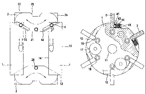
shown embodiment example comprises two ~~lamping plates l, a
set of six clamping wedges 2 as well as an actuation means 3.
One may also envisage a different number of clamping wedges 2,
preferably between three and twenty depending on the pipe
inner diameter. The clamping plates 1 are arranged at an axial
distance to one another along a common axis formed by the
actuation means 3. Each of the two clamping plates 1 comprises
an inner end face 14 facing the respe~~tive other clamping
plate as well as an outer end face 15 facing away to the
outside.
On the circumferential surfaces 13 of the clamping plates
1 there are arranged a plurality of grooves 12, which with the
shown embodiment example are arranged uniformly at an angular
distance of 60°. The grooves 12 extend over a part of the
circumferential surface 13 as well as over a part of the inner
end-face 14 in a manner such that their groove base 16 is not
CA 02401631 2002-09-06 . _....,
aligned parallel to the common axis of the clamping plates 1,
but is slanted in a cone-like manner in the radial direction
by an angle (i. In their center the clamping plates further
comprise a plurality (six in the shown embodiment example) of
5 bores 18 for flange screws. Furthermore in one of the two
clamping plates 1 there are provided a p:Lurality of (three in
the shown embodiment example) gas lead-throughs 17.
The clamping wedges 2 are arranged in a bridge-like
10 manner between the two clamping plates 1,. The clamping wedges
2 are of an approximately trapezoidal shape with a shorter
inner edge 21 and a longer outer edge 22. Connecting to the
two ends of the inner edge 21 there is in each case an oblique
edge 23 which finally leads to the outer edge 22 via in each
15 case an end-face edge 24. The oblique edge 23 is inclined by
the same angle !3 with respect to the inner edge 21 with which
the oblique groove base 16 is inclined with respect to the
axis direction. In the middle of the outer edge 22 there is
provided a relief 25 roughly in the region in which the ends
of the pipes clamped by the clamping device are to be welded
to one another. Lying opposite this roughly in the middle of
the inner edge 21 there is provided a receiving opening 26 for
a tension spring 20.
In the assembled condition of the clamping device the
clamping wedges 2 with their oblique edge 23 are applied into
the grooves of the clamping plates. At the same time the
oblique edges 23 rest on the groove base 16 of the grooves 12
in an essentially flat manner thanits to both equal
inclinations about the angle 13. With this arrangement, with a
relatively large axial distance between the two clamping
plates 1, it is achieved that the clamping wedges 2 with their
.._cA 02401631 2002-09-06
16
respective outer regions of the oblique edges 23 rest on the
groove base 16 of the clamping plates 1, so that the outer
edges 22 of the clamping wedges 2 only project beyond the
circumferential surface 13 of the clamping plates 1 by a small
distance; on the other hand with a re~~atively small axial
distance of the clamping plates 1 to one another the clamping
wedges 2 with their inner region of the oblique edges 23 lie
on the groove base 16 of the grooves of the clamping plates,
so that the clamping wedges 2 project from the circumference
13 of the clamping plates 1 by a large distance. As such by
way of changing the axial distance of the clamping plates 1,
the position of the clamping wedges 2 in the radial direction
may be changed. The connection at the same time as described
previously is such that with an approac)zing of the clamping
plates 1 to one another, the clamping wedges 2 move radially
outwards.
For changing the axial distance of the clamping plates
there is provided an actuation means 3. It comprises an
actuation member 31 as well as a pull rod 32. The actuation
member 31 by way of fastening means which have not been
represented is fastened on the end face 15 of one of the two
clamping plates via a flange plate 33, with which in the
embodiment example shown in Fig. 2 this i~ shown on the right.
The actuation member 31 acts on the pull rod 32 which extends
through the two center bores 11 of the t.wo clamping plates 1
and which is fastened in a tension-proof manner on the one of
the two clamping plates 1 which is farthest from the actuation
member 31. Usefully for this, as is shown in Fig. 2, the two
center bores 11 of the two clamping p7.ates 1 are designed
differently large. The center bore 11 of the clamping plate 1,
which is closer to the actuation member 31, with the fastening
_ _ CA 02401631 2002-09-06 _
17
flange 33 has a larger diameter which is sufficient for a
passage of the fastening spindle 32. The center bore 11 of the
clamping plate further from the actuation member 31 (in Figure
2 the one on the left) has a smaller diameter and is provided
with an inner thread for the tension-proof accommodation with
an outer region of the pull rod 32 provided with an outer
thread. The actuation member 31 cooperates with the pull rod
32 in a manner such that the pull rod 32 is moved either
towards the actuation member 31 or away from it. By way of
this the axial distance of the two clamping plates 1 to one
another changes, by which means on account of the inclination
by the angle f3, the clamping wedges 2 move inwards or
outwards. With the shown embodiment example the actuation
member 31 is designed as a hydraulic control element; however
also other embodiment types are conceivable, for example in
the form of an electric motor acting on a threaded spindle, a
pneumatic drive or a purely mechanical actuation via threaded
spindles.
In order to hold the clamping wedges 2 on the clamping
plates there is provided a guide 4. It comprises an elastic
holding means 41 which is arranged on the clamping plate 1, as
well as a guide channel 42 cooperating with this, which is
arranged on the clamping wedges 2. The falastic holding means
41 comprises a locking ball 43 which is impinged by a spring
44. The elastic holding means 41 with the locking ball 43 as
well as the spring 44 are in each case arranged in a bore 19
of the clamping plate 1. The bore 19 is designed on the
clamping plate 1 in a manner such that, proceeding from the
lower region of the grooves close to the groove base 16, it
extends in the tangential direction through the clamping plate
1 until it finally exits the circumferent:ial surface 13 of the
CA 02401631 2002-09-06
18
clamping plate 1 roughly in the region be-_ween two neighboring
grooves 12. The bore 19 is provided with <~n inner thread which
is designed for accommodating a hollow bolt 45. The hollow
bolt 45 with its outer thread engages into the inner thread of
the bore 19 and thus may be screwed into the bore 19. In its
hollow shank the hollow bolt 45 accommodates the spring 44
together with the locking ball 43. At the same time that end
of the hollow space of the hollow bolt 45 which is proximal to
the head forms the counter bearing for the spring 44. By way
of screwing the hollow bolt 45 into the. bore 19 to varying
degrees, the biasing force of the spring 44 may be set with
which then finally the locking ball 43 acts on the guide
channel 42 of the clamping wedge 2 and th~sn holds this firmly.
The guide channel 42 of the clamping wedges 2 runs
parallel roughly over the whole region of the oblique edge 23.
With this it is achieved that independently of the axial
distance of the clamping plates 1 and thus of the
predetermined radial position of the clamping wedges 2, the
guide channel 42 is always arranged roughly at the same
distance to the groove base 16 of the groove 12, so that in
the normal case the locking ball 43 of the guide 4 may
constantly engage into the guide channel 42 and thus holds the
clamping wedges 2 on the clamping plates 1.
In this manner it is achieved that thanks to the guide 4,
the clamping wedges 2 may be displaced relatively easily along
their provided path on the clamping plates 1. If however the
clamping wedges 2 attempt to leave the path envisaged for
them, for example caused by an incorrect position of the
clamping device or an ovality of the pipe end or ends, then
the guide 4 counteracts the considerable resistance which may
CA 02401631 2002-09-06
19
however be overcome, since for this the locking ball 43 must
be moved against the force of the spring 44 out of its normal
position in the guide channel 42. By way of this, on the one
hand a secure guiding of the clamping wedges 2 on the clamping
plates 1 is achieved, without however on the other hand
completely preventing a movement of the clamping wedges 2 out
of their normal position which is required with incorrect
positions.
The clamping device further comprises a centering aid 6
and a forming gas means 7. The centering aid 6 consists of
three spacers 61 which are arranged star-shaped and which at
their outer end comprise a thickening 62 with a contact
surface 63 envisaged for bearing on the inner surface of the
tubes to be welded. They serve for ce:ztering the clamping
device in the tubes. The forming gas means 7 comprises a
supply pipe 71 which is connected to the flange plate 33 and,
via a suitable bore 43 in the flange plate 33 and the openings
17 in the clamping plate on which the flange plate 33 is
fastened, is led to the inner space between the two clamping
plates 1. At that end of the gas openings 17 which is on the
side of the inner space, there are provided sintered fine
filters 72. In the flange plate there i=; provided an annular
channel ( not shown ) in order with the one forming gas supply
conduit 71 to supply the plurality of gas passage openings 17
with forming gas. In each case on the outer end faces 15 of
the two flange plates there are arranged forming gas seals 74
which in their radial outer region are provided with sealing
lips 75 for bearing onto the inner pipe surface of the pipe
ends to be welded to one another. At the same time the
dimension of the sealing lips 75 is selected such that they
have a somewhat larger diameter than the inner diameter of the
CA 02401631 2002-09-06
pipe ends 91, 92 to be welded to one another in order to
achieve an adequate bearing of the sea:Ling lips 75 on the
inner surface of the pipe ends 91, 92. In this manner the
region between the two forming gas seals 75 with the clamping
5 device is separated in a gas-tight manner from the remaining
inner space. By supplying a suitable forming gas via the
forming gas supply means 7 one may thus produce a gas
atmosphere which is favorable for welding. Excess forming gas
may be led away via bleed channels 76.
In Fig. 3 and 4 there is shown the application of the
clamping device according to the invention. In Fig. 3 the
clamping device is shown in the normal position, i.e. in the
correctly aligned position. In Fig. 4 the clamping device is
shown in an incorrect position, i.e. in an incorrectly aligned
position. One recognizes that in Fig. 3 the two pipe ends 91,
92 to be welded to one another are aligned coaxially to one
another. As such the clamping wedges 2 with their outer edge
22 are parallel to the common middle axis of the pipe ends to
be welded and thus also to the clamping device. The clamping
plates 1 are arranged parallel to one another perpendicular to
the axial direction, i.e. arranged radially aligned. In
contrast in Fig. 4 one recognizes that the clamping wedges 2
on account of the axial shifting of the pipe ends to be welded
to one another are not aligned parallel to the pipe middle
axis, but rather are tilted. Accordingly the clamping plates 1
are also tilted out of their normal position into one of the
radial planes. As one may particularly recognize in the region
of the transition between the clamping plate 1 and the lower
clamping wedge 2, on account of the incorrect position, the
oblique angles between the groove base 2.3 of the grooves 12 of
the clamping plates 1 as well as the oi~lique edge 23 of the
CA 02401631 2002-09-06
21
clamping wedges 2 no longer correspond. By way of this the
clamping wedges no longer lie on the groove base 16 in a flat
manner, but are deflected beyond this into an incorrect
position. The guide 4 thanks to the elastic holding means
permits such an incorrect position without at the same time
damage occurring to the clamping device or a jamming at the
guide 4 occurring. For this the locking ball 43 is moved out
of the guide channel 42 against the force of the spring 44 so
that the clamping wedges 2 may be tilted. out of their normal
position. Furthermore the guide 4 on account of its bias by
the spring 44 attempts to lead back the clamping wedges 2 to
their normal position. Finally by way of actuating the
clamping means and the reduction of the axial distance between
the clamping plates on account of the radially outwardly
directed movement of the clamping wedges 2 which is effected
by this actuation, one achieves a mutual alignment of the two
pipe end pairs 91, 92. Furthermore the tension spring 27 in
the incorrect position (see Fig. 4) is deformed with respect
to the normal position (see Fig. 3) and therefore exerts an
additional restoring force.
In Fig. S and 6 there are shown sets of various clamping
wedges 2', 2 " . Of the clamping wedges which are shown in Fig.
5, in each case depending on the inner diameter of the pipe
ends to be welded to one another, one selects those clamping
wedges 2' which have a fitting size, and applies these into
the clamping plates 1. The exchange is made simple thanks to
the elastic holding means with the locking ball 43 biased by a
spring 44. The clamping wedges to be exchanged may be removed
by a simple pulling out of the grooves 12, whilst the clamping
wedges which are to be newly applied may in a suitable manner
be easily brought into the grooves 12. The achievement of the
_ _ .__._.. _.. . CA 02401631 2002-09-06
22
correct position of the clamping wedges 2 is simplified by the
elastic holding means of the guide ~~ according to the
invention. According to the bias of the spring 44 the reaching
of the normal position can be clearly felt and where
appropriate also heard.
With the embodiment example shown in Fig. 6 the clamping
wedges 2 " are designed two-piece. They consists of a sliding
piece 27 and of an attachment piece 28. The sliding piece 27
is provided on the side of the clamping plate and comprises
the shorter inner edge 21 as well as the oblique edges 23. The
attachment piece 28 is distant to the clamping plate, i.e.
provided on the side of the pipe and comprises the longer
outer edge 22 for contacting the pipe inner surface with the
relief 25. For fastening the attachment piece 28 on the
sliding piece 27 usefully the attachment piece 28 comprises a
relief 29 into which the sliding piece 27 is introduced with
its outer region. In order to fasten the attachment piece 28
securely on the sliding piece 27 there are provided a
plurality of fastening screws 20 which are guided through
suitable bores in the region of the relief 29 of the
attachment piece 28 and the corresponding outer region of the
sliding piece 27.
Of the attachment pieces 28 there are provided sets in
different sizes which according to requirement may be
assembled onto the sliding pieces 27. a~he adaptation of the
clamping device to the inner diameter of the pipe ends to be
welded to one another with this embodiment form is thus
effected in that the attachment pieces c8 are exchanged. This
not only keeps the manufacturing costs for the sets small, but
_ .......____~._~._ _ .... CA 02401631 2002-09-06
23
also permits a simple exchange of the attachments pieces 28
which are particularly prone to wear.
In order to simplify the handling of the sets of clamping
wedges, the tension spring 20 which connects the individual
clamping wedges of a set of clamping wedges to one another is
designed openable. For this it comprises an eyelet 201 as well
as a hook 202 at its respective ends which when the clamping
wedges have been applied into the guide slots are connected to
one another and thus represent a loss securement additionally
to the guide. 4. For removing the set of clamping wedges the
hook 202 only needs to be taken out of the eyelet 201,
thereafter the clamping wedges 2 may be removed individually
from the guide slots 12, in the removed condition the
individual clamping wedges are then held on one another by the
tension springs 20. With this the danger of any inadvertent
detachment of one of the clamping wedges from the remaining
ones is prevented.
In Fig. 7 there is shown a spreader ring 8 for the
clamping device according to the invention. It is formed by
segments, in the shown embodiment example three segments 81,
82, 83. Each of these segments extends over an angle of about
120° so that the three segments are pressed together roughly
into a complete ring. In the spread condition the spreader
ring 8 is not completely circumferential, since between the
individual segments there arise gaps depending on the
condition of spreading. Each of the segments 81, 82, 83 of the
spreader ring 8 is manufactured of a high-strength material,
such as stainless steel. Its main body 84 comprises a raised
pressure saddle 85 on its outer circumferential surface, which
preferably runs over the whole region of the outer
__ .. _..... _... ____._._ _.. . ._ . -cA 02401631 2002-09-06
24
circumferential surface. The pressure saddle 85 in the axial
direction comprises only a relatively small extension which is
a fraction of the axial extension of the main body 84 of the
ring segments 81, 82, 83. Preferably the axial extension of
the pressure saddle 85 is about 2 - 8 mm, preferably 4 - 6 mm.
A double bevelling 86 is arranged on the inner circumferential
surface of the main body 84. The bevelling 86 is inclined at
an angle y with respect to the axial direction. For emphasis
the angle y has been exaggerated in size; preferably it lies
in the range of 3° to 35°, furthermore preferably at about
10°.
As is shown in Fig. 8a, the spreader ring 8 with its
segments 81, 82, 83 is placed onto the clamping wedges 2 " ' .
If the clamping device is actuated in the described manner,
the clamping wedges 2 " ' move outwards in the radial
direction, and with this the segments 81, 82, 83 of the
clamping ring 8 also move outwards, by which means finally the
pressure saddle 85 acts on the inner pipe surface and widens
this. So that a sufficient space remains for accommodating the
spreader ring 8, here with the applied clamping wedges 2 " it
is preferably the case of those which ai_-e smaller than those
clamping wedges 2 which are used for clamping the clamping
device in the pipe. Preferably these clamping wedges 2 " '
comprise a relief 25' which has a contour which fits for
receiving the segments 81, 82, 83 of the clamping ring 8.
With the embodiment example shown in Fig. 8b the segments
of the clamping rings 8 are arranged directly between the two
clamping plates 1; the clamping wedges 2 here have been
removed. The clamping plates 1 on their outer edge which face
each other in each case comprise a chamfer 10. This chamfer 10
... . CA 02401631 2002-09-06 _. .. ~.. _ .",.,.
has the same angle y as also the bevelling 86 of the spreader
ring 8. By way of this the main body 84 of the segments 81,
82, 83 of the clamping ring 3 with the bevelling 86 rests
flatly on the chamfer 10. By changing the distance between the
5 clamping plates 1 with this the segments 81, 82, 83 of the
spreader ring 8 are moved in the radial direction. By way of
activating the actuation means 3 and by way of the change of
the distance between the clamping plates 1 created by way of
this, in the manner which has already been described a radial
10 movement of the segments 81, 82, 83 of th~a spreader ring 8 may
be effected in order thus to carry out an widening of the
tube.
With a preferred variant the clamping wedges 2' are
15 provided with rotary feet 220 on one side. For this the
clamping wedges 2' comprise a passage opening 221 running from
the inside to the outside which is provided with an inner
thread and into which there is screwed an adjusting screw 222.
The adjusting screw 222 at its outer end comprises a head 223
20 at its outer end. By way of rotating the adjusting screw 222
in the passage opening one may change the position of the
adjusting screw 222 so that the distancE~ of the head 223 to
the outer side 22 of the clamping wedges 2' may be changed.
Thanks to the adjusting screw 222 with t:he heads 223 one may
25 also weld together those tubes which have a different inner
diameter. The adjusting screw 22 is adjusted according to the
difference of the diameter of the two tubes to be welded to
one another so that the clamping wedge 2' on the side with the
rotary foot 22 may be placed into the pipe with the larger
diameter and on the side without the adjusting screw into the
pipe with the smaller diameter.
.... _ ... CA 02401631 2002-09-06
26
Indeed with complicated welding locations, but also with
others, it may be particularly advantageous if one creates an
observation possibility for the welding location or the
completeness and quality of the weld seam. with an
advantageous embodiment form, for this, one of the clamping
plates comprises an axial passage opening which has not been
shown, into which there is applied an axially displaceable and
rotatable camera housing in a flush manner. By way of
displacing the camera housing towards t:he welding location
with a complete revolution of the camera housing the whole
length of the weld seam may be observed and inspected with
regard to its quality. Preferably for this the camera
additionally comprises an illumination means. So that the
camera in the camera housing does not become damaged when
welding, the camera housing is retracted into the clamping
plate from the welding location when no observation is carried
out. For transmitting the picture signals to a control. monitor
lying at the oustide one may provide a cable connection or a
wireless transmission, for example by way of radio.