Note: Descriptions are shown in the official language in which they were submitted.
CA 02402482 2002-09-04
1
RECOIL CONTROL MECHANISM FOR A WEAPON
Technical Field
The present invention relates to a weapon and in particular to a recoil
control mechanism for a weapon. The invention will be described generally in
relation to a firearm, however it is to be understood that the invention is
applicable to other forms of weapons for firing a projectile. Thus the weapon
may, for example, be a large calibre weapon which is supported on a mounting
such as a stand or platform instead of a hand held portable weapon such as a
firearm.
In this specification the term "projectile" is to be understood as
encompassing one piece generally solid projectiles such as bullets, pellets,
darts, flechettes, artillery warheads, projectiles as in for example WO
97/04281,
mortar shells (eg. 120 mm) or rocket boosted artillary shells, plus multiple
piece
charges which are fired as one, such as the shot in a shotgun cartridge or a
plurality of bullets fired as one.
Background
A problem with all weapons which fire a projectile, particularly those that
rely upon detonation of an explosive propellant, is recoil. That is, firing
the
weapon (for example by detonation of a charge of explosive propellant within
the weapon) produces a forward propelling thrust on the projectile and an
equal
and opposite rearward force, or recoil. Recoil limits the accuracy and
portability
of weapons. First it produces a force which has the effect of rotating the
weapon about the centre of gravity of the weapon and its support (which for a
firearm would be the shooter), resulting in vertical climb and lateral drift
of the
muzzle end of the barrel for succeeding firings. Recoil forces also cause
torque, which has the effect of `twisting' the weapon. The muzzle is thrown
off
the target in an irregular half circular motion around the longitudinal axis
of the
barrel. Similar to the effect of muzzle climb, the time of reacquisition of
the
target is therefore increased for subsequent rounds and accuracy is therefore
significantly affected.
CA 02402482 2006-09-14
2
During automatic firing recoil can significantly affect the accuracy of the
succeeding rounds. Second, the force of recoil must be absorbed by the
weapon, or the shooter if the weapon is a firearm, or transmitted to a support
mounting and thus to ground for heavier weapons such as artillery pieces. Thus
it
may cause discomfort and fatigue or even injury to a shooter, or require
heavier
supporting structures, or complex "soft" mounting carriages for mobile
artillery
weapons. Large masses are sometimes used in firearms to absorb the recoil
velocity, however this compromises portability.
Clearly, if the recoil of a weapon could be substantially reduced if not
eliminated within the weapon itself, it would reduce the above problems.
There are many known recoil reducing mechanisms, including
arrangements which are initiated by the rapidly expanding gases produced by
the
detonation and burning of an explosive propellant. Generally, however, the
known arrangements effectively only reduce the recoil without cancelling or at
least substantially eliminating it.
Summary of the Invention
The present invention is directed towards the process of an improved
recoil control mechanism.
The invention is characterised by the generation of a forward counterforce
to the rearward recoil simultaneously with absorption of rearward recoil force
momentarily after propulsion of the projectile is initiated.
Accordingly, in a first aspect the invention provides a recoil control
mechanism for a weapon for firing a projectile in a forward direction which
includes a first mass and a second mass which are substantially simultaneously
driven in substantially opposite directions upon firing, wherein the first
mass is
driven in the forward direction to counter a rearward recoil of the weapon and
the
second mass is driven in the rearward direction for absorbing some of the
recoil
force.
The first mass and the second mass are solid inertial weights.
Preferably the mechanism includes a frame, the first mass and the second
mass being associated with the frame for the frame to guide their respective
forwards and rearwards movement, and including a force absorbing means which
is operative between the second mass and the frame and a force transferring
means which is operative between the first mass and the frame.
CA 02402482 2002-09-04
R~"'~d 06 February o00 O
3
In a second aspect the invention provides a method of countering recoii
of a weapon caused by the firing of a projectile, the method including
providing
a first mass to be driven forwardly in the same direction as the projectile to
counter a rearwards recoil force and providing a second mass to be
substantially simultaneously driven rearwardly against a force absorbing means
for absorbing some of the rearwards recoil force.
The generation of a forward counterforce simultaneously with absorption
of the residual recoil force over the time period of the recoil, allows the
achievement of a resultant force-time characteristic which may be reasonably
predetermined. For example, for a projectile which is fired by detonation of
an
explosive propellant, the recoil force of a weapon is reasonably calculable
from
knowledge of the amount and type of propellant and the masses etc. that are
involved, or it may be empirically determined experimentally, and from this
appropriate parameters for the counterforce and recoil absorption sub
mechanisms can be calculated (and possibly experimentally adjusted) to give a
predetermined resultant force-time characteristic. Thus the invention gives an
improved recoil control mechanism. It is envisaged that in some embodiments
of the invention, the recoil of the weapon may be at least substantially
eliminated if not fully cancelled (that is, the resultant force is
substantially zero
over the recoil time period). It is also considered that a resultant forward
force
could be generated.
Preferably the first mass is a barrel and the second mass is a breech
block of the weapon and a means is provided associated with the barrel and a
frame of the weapon for transferring a forwards force to the frame from the
forward motion of the barrel. This means may include a compression spring or
pneumatic or hydraufic piston and cylinder arrangement or electromagnetic
means which is operative to return the barrel to its firing position.
The barrel and the breech block are also preferably biased towards each
other relative to the frame of the weapon. This bias may be provided by a
tension spring which is connected between the barrel and the breech block.
Thus, as force from the forward momentum of the barrel is being transferred to
the frame, the rearwards recoil force imparted to the breech block is being
absorbed by the tension spring. Thus the tension spring provides a force
absorbing means against which the breech block is driven. The tension spring
W aE l4, YIGHODE lc {CAfM1=?0. dut
AMENDED StiEE'r
IPEA/AU
CA 02402482 2002-09-04
WO 01/65195 4 PCT/AUO1/00220
may also be operative to restrain the breech block in its firing position
momentarily upon detonation of the propellant to provide an adequate reaction
surface for initiating the forward movement of the projectile and then to
return it
to its firing position after its rearward movement.
Alternatively the bias of the breech block and the barrel towards each
other may be provided by means acting independently between the barrel and
the frame and the breech block and the frame. Such means acting between the
barrel and the frame may constitute the above described means for transferring
a forwards force to the frame from the forward motion of the barrel. The
independent means may each comprise a helical spring.
Although the preferred embodiment combines simultaneous "blow
forward" of the barrel and "blow back" of the breech block to control recoil,
as
described above, it is to be understood that the invention may be realised in
alternative embodiments. For example, it is envisaged that the first mass and
the second mass may be additional components and that a gas for driving them
apart may be tapped from the barrel or firing chamber. The recoil control
mechanism may also be provided as an attachment per se for a weapon.
Various of the foregoing or following features for biasing the breech block
and
barrel and providing gas reaction surfaces may be adapted to the masses of
such alternative embodiments.
In the preferred arrangement wherein the first mass is a barrel and the
second mass is a breech block of the weapon, a chamber for receiving a
cartridge containing the projectile (such as a bullet) and explosive
propellant is
preferably provided at a loading end of the barrel. The chamber is associated
with the barrel and the breech block to provide an interposed gas contact
region
therebetween for receiving expanding gases from the chamber upon firing of
the projectile from the cartridge. Thus, upon firing of the cartridge,
expanding
gases from the propellant force the projectile from the cartridge and propel
it
through the barrel, and momentarily after initiation of the projectile's
movement,
the expanding gases following the projectile which emerge from the cartridge
into the chamber expand into the interposed gas contact region to blow the
barrel forward and simultaneously blow the breech block backwards to thereby
reduce if not eliminate the recoil of the weapon. The chamber may be provided
by the barrel, by the breech block, or the barrel and the breech block in
CA 02402482 2002-09-04
WO 01/65195 5 PCT/AUO1/00220
combination, or by a separate chamber member. Preferably the component or
components providing the chamber are in a structural relationship such that
the
interposed gas contact region is defined in part by at least two facing
reaction
surfaces, with each reaction surface being directly or indirectly associated
with
one of the barrel or the breech block. Preferably the reaction surfaces are
substantially normally orientated relative to the forward and rearward
directions
to maximise the forces applied thereto in the forward and rearward directions
by
the gas pressure. The aforesaid structural relationship may be realised by a
telescopic arrangement of one component relative to another, as will be
described in more detail below.
It is to be understood that the weapon will include a firing mechanism for
initiating detonation of the explosive propellant and in the preferred
embodiment
this may include a firing pin associated with the breech block which is
operable
via a trigger mechanism carried by the frame, as is known. The weapon may
also provide for semi automatic or fully automatic operation utilising the
energy
stored during the blow back of the breech block, as is also known, in which
case
a magazine will need to be provided. A suitable firing mechanism and a
mechanism for providing semi or fully automatic operation including a magazine
for the cartridges will not be described in further detail herein as there are
many
such known mechanisms from which a person skilled in the art may choose to
provide suitable such mechanisms for the weapon.
A weapon incorporating the invention, in its preferred form involving blow
forward of the barrel, may include additional features associated with the
barrel
for increasing the forwards momentum thereof. Such additional features
include, for example, the provision of a conical bore for the barrel and/or
muzzle
breaks for redirecting the gas from the barrel, as are known. The weapon in
its
preferred form may be a firearm such as a rifle, shotgun, pistol or revolver.
For a better understanding of the invention, the principle thereof for
various embodiments, as well as a specific embodiment, which are given by
way of non limiting example only, will now be described with reference to the
accompanying drawings (which are not to scale).
CA 02402482 2002-09-04
WO 01/65195 6 PCT/AU01/00220
Brief Description Of Drawinqs
Figures 1 to 4 schematically illustrate the operating principle of the
invention.
Figure 5 schematically illustrates use of a barrel, chamber unit and
breech block for the invention.
Figures 6 A-D and 7A-F illustrate further embodiments in principle.
Figure 8 is a partially sectioned side view of an embodiment of the
invention in the form of an automatic pistol, and
Figure 9 is a partially sectioned view of a portion of the pistol of Figure 8
showing the slide (that is breech block) in its rearmost position.
Detailed Description
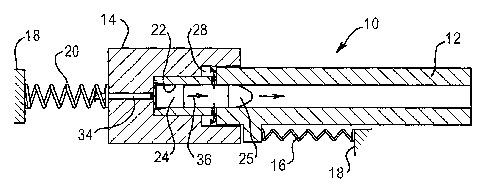
A recoil control mechanism 10 of a weapon as schematically shown in
Figures 1 to 4 includes a first mass which is a barrel 12 of the weapon and a
second mass which is a breech block 14 of the weapon. The barrel 12 is
movable in a forward direction against a biasing means 16 relative to a frame
18 of the weapon and the breech block 14 is movable rearward against a
biasing means 20 relative to the frame 18. The biasing means 16 and 20 may
be helical compression springs. The barrel defines a chamber 22 at its loading
end, for receiving a cartridge 24 with a bullet 25, and is telescopically
received
within a recess 26 in the breech block 14.
The recess 26 of the breech block and the barrel 12 are shaped such
that when in the ready to fire position (Figure 1) they define an interposed
gas
contact region, namely an annular volume 28. Ports 29 provide for gas flow
from chamber 22 into volume 28. The interposed gas contact region 28 is
defined in part by a reaction surface 30 on the barrel 12 and a facing
reaction
surface 32 on the breech block 14. The surfaces 30 and 32 lie substantially
normally to the forward and rearward directions. A firing pin 34 is associated
with the breech block 14.
On firing, the rapidly expanding gases 36 from the explosive propellant in
cartridge 24 propel bullet 25 into the bore of barrel 12 and also flow through
ports 29 into the interposed gas contact region 28 (Figure 2). The very high
pressure gases entering region 28 act on reaction surfaces 30 and 32 and thus
simultaneously force or "blow" the barrel 12 forwardly (arrow A, Figure 3) and
the breech block 14 rearwardly (arrow B, Figure 3). Initiation of the blowing
CA 02402482 2002-09-04
WO 01/65195 7 PCT/AU01/00220
forward of the barrel 12 and blowing back of the breech block 14 occurs
momentarily after firing because of the proximity of ports 29 and chamber 22.
The force of the rearward or recoil movement of the breech block 14 is
absorbed by biasing means 20 which has a suitable characteristic relative to
that of biasing means 16 to ensure it stores a significant portion of the
force
instead of immediately transferring it to frame 18. Simultaneously, the force
from the forward movement of barrel 12 is transferred to frame 18 via biasing
means 16, which has a relatively stiffer characteristic compared to that of
biasing means 20 to ensure that the counter recoil force is quickly
transferred to
the frame 18. Thus the rearward recoil which occurs upon detonation of the
explosive in cartridge 24 and expansion of gases 36 therefrom to propel bullet
25 through barrel 12 is simultaneously both absorbed in biasing means 20 and
countered by an oppositely directed force applied to frame 18 from barrel 12.
The resultant of this may be to totally or at least substantially eliminate
recoil of
the weapon. At the limit of the forward movement of barrel 12 and rearward
movement of breech block 14 (Figure 4) the cartridge 24 is ejected by
ejector 35 and the biasing means 16 and 20 are operative to restore the parts
to
their ready to fire positions.
Figure 5 schematically shows a modification wherein a chamber unit 40
is provided interposed between a breech block 14 and barrel 12 (the
components of Figure 5 which are equivalent to those in Figures 1 to 4 have
been biven the same reference numeral, but note that some features have been
omitted from Figure 5 for clarity). A forward cylindrical portion 42 of
chamber
unit 40 telescopically engages in a wider cylindrical recess 44 in barrel 12
to
provide an interposed gas contact region 28 defined in part by facing reaction
surfaces 30 and 32 of, respectively, the barrel 12 and the chamber unit 40.
With this construction, the ports 29 are eliminated, however it functions the
same as the construction of Figures 1 to 4.
The reaction surfaces of the interposed gas contact region may have any
desired shape. Thus instead of being flat, as shown in Figures 1 to 5, they
may
have curved portions, be fluted, include depressions or be otherwise modified
to
increase the surface area upon which the rapidly expanding pressurised gases
36 act.
CA 02402482 2002-09-04
WO 01/65195 8 PCT/AU01/00220
After the pressure of the expanding gases has reduced, the breech block
14 and barrel 12 are returned to the positions shown in Figure 1 by the energy
stored in biasing means 20 and 16, respectively. A mechanism for automatic
ejection of the cartridge case 24 is indicated at 35 (Fig. 4). A mechanism for
automatic loading of another cartridge in chamber 22 ready for firing is not
shown in Figures 1 to 5, but as is known may be operated by the backward and
then forward motion of the breech block 14, or alternatively the forward and
then rearward motion of the barrel 12, or a combination of both.
Figures 6A to D illustrate in principle a weapon where recoil is controlled
by simultaneous "blow forward" of a barrel and "blowback" of a breech block
without use of an interposed gas contact region. Thus the figures show a
weapon 50 which comprises a frame 52 on which is reciprocally mounted a
barrel 54 biased rearwardly by a compression spring 56. The frame 52 also
carries a breech block 58 which is biased forwardly by compression spring 60.
On detonation of a cartridge 62, the bullet 64 is propelled forwardly and
its motion through the barrel 54 drives the barrel forwardly and this motion
continues after the bullet 64 exits the barrel 54 (figures 6B, C and D). Also
upon firing, a rearwards force from the cartridge 62 is impacted on the breech
block 58 and this drives the breech block rearwardly against the bias of
spring 60. Spring 56 is relatively weak such that a forwards force is
generated
by the moving mass of barrel 54 to counter the rearwards recoil. Some of this
force is transferred to frame 52 via spring 56 such that, combined, a
substantial
forwards counter to the rearwards recoil is generated. Simultaneously the
recoil
force imposed on breech block 58 is absorbed by spring 60. It is considered
that the masses of barrel 54 and breech block 58 and the spring
characteristics
of springs 56 and 60 could be arranged such that recoil is effectively
eliminated.
Figures 7A to F illustrate a weapon 80 having a frame 82 on which is
mounted a barrel 84 and breech block 86. A moveable mass 88 surrounds the
barrel 84. The barrel 84 is biased to its rest position relative to frame 82
by
spring 90, and mass 88 is biased against an abutment 92 on barrel 84 relative
to frame 82 by a double spring arrangement 94. Breech block 86 is biased
forwardly relative to frame 82 by a spring 96. An interposed gas contact
region
is defined by facing surfaces of the abutment 92 on barrel 84 and an end face
of
CA 02402482 2002-09-04
WO 01/65195 9 PCT/AU01/00220
the mass 88 and is in gas communication with a chamber part of the barrel 84
via passages 98.
The sequence of events for recoil control in the weapon 80 upon firing of
a cartridge 100 will be evident from Figures 7A to F. Thus, on detonation, the
barrel is initially driven forwardly against the bias of spring 90 by bullet
102 and
virtually instantaneously gas forces into the gas contact region to drive mass
88
forwardly against double spring 94, the initial portion of which is readily
compressible (Figures 7A and B). Spring 96 drives breech block 86 forwardly
with the barrel 84. Whilst mass 88 continues forwardly, barrel 84 is then
driven
rearwardly by spring 90 and gas pressure on abutment 92 to drive the breech
block 86 rearwardly against spring 96 (Figures 7C, D and E). This extracts the
cartridge case 100 from the chamber end of barrel 84. Mass 88 continues
forwardly, but is now moving against a stronger bias provided by the second
portion of the double spring arrangement 94 until it reaches its forward most
position (Figure 7F), at which point the breech block 86 also reaches
substantially its rear most position. The mass 88 and breech block 86 are then
reset to their initial positions by the energy which is stored in springs 94
and 96,
respectively.
The initial forward movement of barrel 84, breech block 86 and mass 88
combined with the subsequent rearward movement of barrel 84 and breech
block 86 against spring 96 simultaneously with continued forwards movement of
mass 88 against double spring 94 allows for the recoil in the weapon 80 to be
controlled.
An example weapon, namely a pistol 100 incorporating an embodiment
of the invention, comprises a frame 102 (Figures 8 and 9) having a handle 104
within which a magazine 106 is received. Mounted on the frame 102 is a barrel
108 and a breech block in the form of a slide 110. A breech face 112 of the
slide (best seen in Figure 9) closes a chamber 114 provided by a chamber unit
116, and a forward portion 118 of the slide surrounds the barrel 108. Forward
portion 118 of the slide 110 includes a bushing 120 for supporting the forward
end of barrel 108 for relative movement therebetween.
The slide 110 is rearwardly movable relative to frame 102 against the
bias provided by a helical compression spring 122 which acts between a
boss 124 which is pinned to the frame 102 by a pin 126 and a spring holding
CA 02402482 2002-09-04
WO 01/65195 1 O PCT/AU01/00220
bracket arrangement 128 provided on the forward portion 118 of the slide
beneath barrel 108. A pin member 130 (which may be cylindrical) extends
through bracket 124 for guiding and supporting the spring 122 as it compresses
with rearwards movement of slide 110. The frame 102 includes an
extension 132 for covering the spring 122.
The barrel 108 is forwardly movable relative to frame 102 against the
bias provided by a helical compression spring 134 which acts between the
boss 124 pinned to frame 102 and a depending lug 136 of the barrel 108. The
pin member 130 is associated with the lug 136 for supporting spring 134. Pin
member 130 can slide through boss 124. A rib on the lowermost surface of
lug 136 of barrel 108 slides within a groove in the frame 102 to guide the
barrel.
Frame 102 carries a firing mechanism which includes a trigger 138 and
hammer 140 adapted to be cocked by the slide 110 when it moves rearward
from the position shown in full lines in Figure 8. Details of the firing
mechanism
are not shown but may be the same or similar to that in a Colt "Ace" pistol,
upon
which the present embodiment is modelled. When trigger 138 is pulled, the
hammer 140 is released to strike the rear end of a firing pin 142 carried by
the
slide 110.
The chamber unit 116 includes a cylindrical forward portion for
telescopically engaging within a cylindrical recess in the rear end of barrel
108
to provide an interposed gas contact region 144. The gas contact region is
partly defined by facing reaction surfaces of the barrel and the chamber unit.
The rear portion of chamber unit 116 includes a depending extension 146 (see
Figure 9) which includes a slot 148. A pin 150, which is fixed to the frame
102,
passes through the slot 148 whereby the slot and pin 150 in combination define
the forward and rearward limits of movement of the chamber unit 116. A V
spring 152 is retained between the depending extension 146 of chamber unit
116 and a surface of frame 102 to bias the chamber unit 116 towards its
forward most position. Extension 146 includes a rearward projection which has
an inclined upper surface 154 (best shown in Figure 9) for providing a ramp
for
guiding cartridges into the chamber 114.
The slide 110 includes an extractor adapted for engaging and
withdrawing cartridges from chamber 114 when the slide 110 moves rearward.
When the cartridge shell is drawn back by the extractor it is engaged by an
CA 02402482 2002-09-04
WO 01/65195 11 PCT/AUO1/00220
ejector and thrown out through ejection opening 156 in the slide 110 (see
Figure
9).
The magazine 106 holds cartridges 158, the uppermost of which rests
against a depending central rib 160 on the slide 110. The magazine is provided
with a known spring follower to press the cartridges upward successively as
each topmost cartridge is withdrawn and fired by the pistol 100.
Figure 8 shows the pistol 100 loaded and cocked. Upon firing, the
cartridge and chamber unit 116 recoil rearwardly (against the bias of V
spring 152) and at virtually the same instant some of the high pressure
expanding gases enter the gas contact region 144 and impinge on the reaction
surfaces to blow the chamber unit 116 and barrel 108 apart. This drives the
chamber unit 116 and slide 108 rearwardly against the bias of the spring 122.
The chamber unit 116 stops when the forward end of slot 148 contacts pin 150,
but slide 110 continues rearwardly for the recoil force to be further absorbed
by
spring 122. Simultaneously force from the forward movement of the barrel 108
is transferred to frame 102 via spring 134 acting between lug 136 and boss
124.
This force counteracts the recoil, including that caused by extension 146 of
chamber unit 116 striking pin 150 of frame 102. The combined blowing back of
the slide 110 and blowing forward of barrel 108 together with the action of
springs 122 and 134 relative to frame 102 allows for the recoil of the pistol
100
to be substantially eliminated.
The slide 110 moves rearward to the position shown in Figure 9 and thus
recocks the firing mechanism. It is immediately returned forwardly by the
energy stored in spring 122, during which movement its central rib 160 engages
the top most cartridge 158 in magazine 106 and pushes it forwards into
chamber 114 of chamber unit 116, by which time the chamber unit 116 has
been reset by V spring 152. The cartridge 158 is guided into chamber 114 by
the inclined ramp surface 154 of chamber unit 116. The slide 110 holds the
chamber unit 116 forward in the position shown in Figure 8. At the same time
the barrel 108 is returned rearwardly to its normal position shown in Figure 8
by
the energy stored in spring 134. Recocking and reloading have thus been
effected and the pistol 100 is ready to be fired again.
Although only a single detailed embodiment (Figures 8 and 9) has been
described, the principle of the invention is not complex and is adaptable to
other
CA 02402482 2002-09-04
WO 01/65195 12 PCT/AU01/00220
types of weapons without undue experimentation. Thus the invention is to be
understood as applicable to weapons of much larger calibre, including mounted
mobile or stationary artillery weapons. It is also considered that the
invention is
applicable to the types of weapons as disclosed in WO 94/20809 and WO
98/17962.
It is also to be understood that the invention is not restricted to
applications where a projectile is fired via detonation of an explosive
propellant,
whether that propellant be encased, as in for example a cartridge, or
otherwise
presented for firing a projectile, as in for example caseless ammunition, or
whether it be a solid, gaseous or liquid propellant. Thus, the invention is
considered to be applicable to all types of weapons which fire a projectile
and in
which recoil occurs, notwithstanding the means or manner by which the high
pressure is developed that is necessary to propel the projectile forwardly. It
is
considered that such means or manner may include for example
electromagnetic (as in "rail guns") or electrothermal systems, air propulsion
systems of various types and others.
Finally, it is to be understood that various alterations, modifications
and/or additions may be made to the present invention without departing from
the ambit thereof as defined by the scope of the following claims.