Note: Descriptions are shown in the official language in which they were submitted.
CA 02402649 2002-09-10
WO 01/68968 PCT/USO1/07853
-1-
THREAD TAIL CONTROL APPARATUS AND METHOD
Field of the Invention
The present invention relates to quilting machines, and particularly to
an apparatus and a method of controlling a tail of a cut thread.
Background of the Invention:
In sewing machines of various types, threads are applied and
manipulated on opposite sides of a fabric to form one or more patterns of
stitches.
The proper formation of the stitches of each series requires the cooperative
movement and precise timing of cooperating stitching elements. At the end of a
stitching pattern, the thread is cut; and the relative position of the fabric
and the
stitching elements is changed to sew another stitching pattern. Referring to
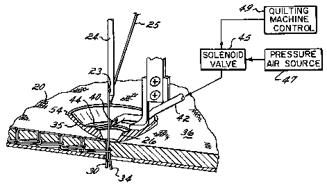
Fig. 5,
Payers of fabric 20 to be stitched are laid out on top of a needle plate 22 of
a quilting
machine. A needle 24~ is connected to a needle drive and mounted above a
presser
foot 28 in a known manner. The presser foot 28 is a bowl-type presser foot
which
is mounted by means of a support 29 to other components of the quilting
machine
in a known manner. The needle 24 and thread 25 reciprocate vertically through
a
hole 26 in the bowl-type presser foot 28, through the layers of fabric 20 and
then
through a hole 30 of the needle plate 22, thereby forming stitching 32 within
the
fabric: After.a pattern. has been stitched;the thread 25 is cut.by a known
thread .
cutting device (not shown) normally located below the needle plate 22.
Thereafter,
the relative position between the layered fabric 20 and the needle 24, presser
foot
28 and needle plate 22 is changed to position the needle 24 with respect to
the start
of another pattern to be stitched.
As the fabric 20 is moved with respect to the needle plate 28 as shown
in phantom in Fig. 5, the thread tail 34 is pulled to a location between the
layered
fabric 20 and the presser foot 28. When that desired relative position between
the
layered fabric 20 and the presser foot 28 is achieved, the stitching cycle is
again
initiated, and as the needle 24 passes through the fabric 20, the thread tail
34
CA 02402649 2002-09-10
WO 01/68968 PCT/USO1/07853
_2_
remains locked under the presser foot 28. When that stitching pattern is
completed
and the layered fabric again moves with respect to the presser foot, the
thread tail
34 hangs from the upper surface 36 of the layered fabric 20 and requires
manual
trimming.
Therefore, there is a need to improve the process so that the manual
trimming of thread tails is not required.
Summary of Invention
The present invention provides a method and apparatus that
substantially improves the efficiency of a process of sewing layered fabric on
a
quilting machine. The method and apparatus of the present invention is
valuable
in reducing the cost of sewing layered fabric on a quilting machine by
eliminating a
labor intensive and time consuming manual operation. Thus, the method an
apparatus of the present invention provides a more consistent, efficient and
higher
quality quilting machine operation and product therefrom.
In accordance with the principles of the present invention and the
described embodiments, an apparatus is provided for removing a thread tail
from
a hole in a presser foot on a quilting machine. The apparatus has an orifice
providing a stream of pressurized air capable of applying a force against a
section
of the thread tail extending between the needle and the hole in the presser
foot.
20; . Th'e pressufized air stream pulls the thread tail through the holevi'n~
he presser.foot
and gathers the thread tail on an upper side of the presser foot. The
apparatus
further has a valve for turning the stream of pressurized air on and off.
In another embodiment, the present invention includes a method of
automatically applying a generally transverse force tb a portion of the thread
tail
extending between the needle and the hole in the presser foot for a duration
sufficient to remove the thread tail from the hole in the presser foot.
In one aspect of the invention, the thread tail extends through the hole
in the presser foot and through the layered fabric material being sewn, and
the
method further comprises maintaining the pressurized air stream for a duration
such
CA 02402649 2002-09-10
WO 01/68968 PCT/USO1/07853
-3-
that all of the thread tail is pulled from the layer fabric material and
through the hole
in the presser foot.
Thus, the apparatus of the present invention has the advantage of
eliminating the labor intensive, time consuming, and expensive manufacturing
operation of manually trimming hanging thread tails from the sewn fabric. The
apparatus of the present invention controls the thread tail in a manner that
permits
the thread tail to be sewn into the layered fabric during a further stitching
operation.
Various additional advantages, objects and features of the invention
will become more readily apparent to those of ordinary skill in the art upon
consideration of the following detailed description of the presently preferred
embodiments taken in conjunction with the accompanying drawings.
Brief Description of Drawings
Fig. 1 is a partial sectioned perspective view of a presser foot and
other stitching elements of a quilting machine in accordance with the
principles of
the present invention.
Fig. 2 is a partial top view of the presser foot of Fig. 1 with a thread tail
beneath the presser foot.
Fig. 3 is a partial top view of the presser foot of Fig. 1 with the thread
tail removed from beneath the presser foot.
:. ~ Fig'. 4'is a cross= ectional view taken.along line 4-4 ofiFig~. 3. ~. ~
,'
Fig. 5 is a partial sectioned perspective view of a prior art presser foot
and other stitching elements of a quilting machine.
Detailed Description of the Invention
Referring to Figs. 1 and 2, as the layered fabric 20 changes position
with respect to the presser foot 28, the thread tail 34 is captured between a
lower
surface 35 of the presser foot 28 and the top surface 36 of the layered fabric
20.
As previously discussed, in the absence of the invention, subsequent stitching
by
the needle 24 will result in the thread tail 34 hanging from the surface 36.
Thus,
CA 02402649 2002-09-10
WO 01/68968 PCT/USO1/07853
-4-
with each pattern stitched, the thread tail 34 must be manually trimmed and
removed.
In order to eliminate the hanging thread tail 34, the present invention
utilizes an air jet from an orifice 40 at one end of a tube 42. As shown in
Fig. 2, the
orifice 40 of the tube 42 is oriented to direct a stream of pressurized air 43
substantially diametrically across the hole 26 of the presser foot 28. The
tube 42
has a nominal inside diameter of 0.0625 inches and is made from any suitable
material, for example, a malleable soft copper, brass, steel, plastic, etc.
The other
end of the tube 42 is connected to a valve 45 that, in turn, is fluidly
connected to a
source of pressurized air 47. The operation of the valve 45 is controlled by a
quilting machine control 49 as will be subsequently described. The pressurized
air
stream from the orifice 40 applies a sufficient force on the thread 34 to move
the
thread tail 34 to a location on an upper side of the presser foot 28. The
pressurized
stream of air 43 is maintained for a sufficient duration to pull the full
length of the
thread tail 34 upward through the hole 26 of the presser foot 28.
Referring to Figs. 2-4, a baffle 46 is mounted on the presser foot 28.
The baffle 46 has an outer edge 52 with an arcuate profile that matches the
circular
profile of the outer peripheral edge 54 of the presser foot 28. The baffle 46
has an
inner edge 53 that is substantially linear and extends between the ends ~48,
50 of
the outer edge 52, thereby forming a substantially crescent-shaped baffle 46.
The
baffle 46 is attached to th,e peripheral edge 54~ of the press,.er foot 28 at
the ends 48~v.
50 by an appropriate process, for example, welding, brazing, etc. Thus,
referring
to Fig. 4, the arcuate edge 52 of the baffle 46 is unattached to, and forms a
small
gap 55 with, the peripheral edge 54 of the presser foot 28. The gap 55 is, for
example, approximately 0.030 inches. Consequently, the gap provides a path for
the pressurized air stream 43 from the orifice 40 in a manner to facilitate
the lifting
of the thread tai! above the presser toot 28.
In the illustrated embodiment of Figs. 2-4, the baffle plate is mounted
on the peripheral edge 54 of the presser foot 28 such that the inner edge 53
of the
baffle plate 46 forms an angle a of approximately 9° rotated
counterclockwise from
CA 02402649 2002-09-10
WO 01/68968 PCT/USO1/07853
-5-
a first diameter 57 coincident with a centerline of the mounting bracket 29.
The tube
42 is mounted within the presser foot 28 such that the pressurized air stream
is
directed out of the orifice 40 at an angle ~3 of approximately 5°
rotated
counterclockwise from a second diameter substantially perpendicular to the
first
diameter. It should be noted, however, that those angles are not critical to
the
operation of the invention. Normally, the pressurized air stream from the
orifice 40
should be directed along a path that is approximately perpendicular to the
inner
edge of baffle plate 46.
Care should also be taken that the pressurized air stream does blow
the thread 25 out of the eye 23 from the needle 24 (Fig. 1). Therefore, the
pressurized air stream from the orifice 40 should be directed at the needle 24
in the
same direction as the thread 25 passes through the needle. In other words, the
pressurized air stream from the orifice 40 should be directed generally at the
side
of the eye 23 of the needle 24 that receives the thread 25.
The baffle 46 functions to direct the pressurized air stream across the
presser foot 28 in a direction moving the thread tail 34 to the interior of
the presser
foot 28 as shown in Figs, 3 and 4. Hence, the thread tail 34 is loosely
gathered on
top of the presser foot 28 and is not locked between the lower surface 35 of
the
presser foot 28 and the upper surface 36 of the layered fabric 20. Therefore,
when
stitching is again initiated, the needle 24 sews both the thread 25 and the
thread tail
34 into the layered fabric 20: Thus, the thread tail 34~ is sewn into the
layered fabric
20 and there is no requirement for trimming the thread tail 34 after the
pattern is
stitched. Referring to Fig. 4, normally, the orifice 40 at the end of the tube
42 is
uncut in a plane having an angle ~ of approximately 30° with the bottom
surface 44
of the presser foot 28.
in use, the process of capturing the thread tail 34 on the upper side
of the presser foot 28 is commanded by the quilting machine control 49 and is
executed in association with a trim cycle that cuts the thread 25 in a known
manner.
At substantially the same time that the quilting machine control 49 provides
an
output signal to a knife commanding the knife to cut the thread, the quilting
machine
CA 02402649 2002-09-10
WO 01/68968 PCT/USO1/07853
-6-
control 49 provides a signal over an output 51 to a valve 45, for example, an
electrically operated solenoid valve, causing the valve 45 to switch to an
open state.
In the open state, the valve 45 permits the pressurized air to flow from the
source
47 through the fluid path formed by the tube 42 and out the orifice 40. A
timer within
the quilting machine control 49 is also started so that the valve 45 remains
open for
a period of time, for example, 2-5 seconds. The pressure magnitude of the
pressurized air and the duration of the timer must be sufficient to allow the
force of
the air stream 43 on the recently cut thread tail 34 to pull the full length
of the thread
tail 34 through the layered cloth 20 and the hole 26 of the presser foot 28.
When
the timer in the control 49 expires, the quilting machine control 49 switches
the state
of the signal on its output 51, thereby switching the state of the valve 45
and
terminating the flow of pressurized air from the source 47 and out the orifice
40 of
the tube 42. Therefore, when the machine starts its next stitching cycle, the
cut
thread tail 34 is not trapped by the presser foot, but instead, is gathered
loosely on
top of the presser foot 28. And, the needle 25 sews the thread tail 34 into
the
layered fabric 20, leaving no tail from the top surface 36 and only a small
knot on
the opposite side of the fabric.
The pressurized air stream 43 of the present invention moves the
thread tail to a location in which the tail 34 is not clamped by the presser
foot 28, but
is free to be sewn in the layered fabric by subsequent stitching. ~y
maintaining
such control of the thread"tail,~the labbr~iritensive, time-consuming' a'nd
eXpensive' .
process of having to manually trim thread tails from each of the, patterns
stitched is
eliminated. Thus, the invention reduces the labor content, the time of
manufacturing, and it presents a substantial cost savings to the manufacturer.
While the present invention has been illustrated by a description of one
embodiment and while that,embodiment has been described in considerable
detail,
it is not intended to restrict or in any way limit the scope of the appended
claims to
such detail. Additional advantages and modifications within the spirit and
scope of
the invention will readily appear to those skilled in the art. For example, in
the
described embodiment, the thread tail 34 is removed from the fabric at the end
of
CA 02402649 2002-09-10
WO 01/68968 PCT/USO1/07853
_7_
a stitching pattern and before the relative position between the layered
fabric 20 and
the presser foot 28 is changed. Obviously, it is easier to move the thread
tail 34 to
the upper side of the presser foot prior to the thread tail becoming pulled
beneath
the presser foot 28. However, as will be appreciated, the thread tail may be
moved
at a different time in the stitching cycle, and the thread tail may be also
pulled from
between the lower side of the presser foot and the upper surface of the
layered
fabric.
Further, in the described embodiment, the presser foot 28 is shown
and described as a bowl-type presser foot. As will be appreciated, the
invention is
applicable to other types of a presser foot, for example, a flat presser foot.
Regardless of its design, the presser foot should have a size that permits the
thread
tail to be moved to the top of the presser foot, so that it is not subject to
being
trapped between a lower side of the presser foot and the fabric. In addition,
while
the described embodiment shows a single needle, as will be appreciated, the
thread
tail control of the present invention may be applied to machines having any
number
of needles.
In addition, the orifice 40 is described as being circular. As will be
appreciated, the orifice 40 may be elliptical or any other geometric shape.
Further,
in the described embodiment, the orifice 40 is described as having a nominal
inside
2o diameter of 0.0625 inches. However, as will be appreciated, the orifice 40
may be
,smaller or larger.
The described embodiment recites specific values for the angles a,
Vii, ~, the gap between the baffle plate outer edge 52 and the peripheral edge
54 of
the presser foot 28 and the time duration of the air stream. As will be
appreciated
those are values that have been chosen for a presser foot of a specific design
in a
particular application. Depending on the size and geometry of the presser foot
28
and other application related conditions, other values for those variables may
be
used; and further, some experimentation with respect to those variables may be
required to achieve the desired results.
CA 02402649 2002-09-10
WO 01/68968 PCT/USO1/07853
_g_
The invention is particularly suitable for use on multi-needle quilting
machines such as described, for example, in commonly assigned U.S. patents
5,154,130 and 5,544,599, hereby expressly incorporated herein by reference.
The
invention is also useful on single needle quilting machines as, for example,
described in commonly assigned U.S. patents 5,650,916, .5,685,250 and
5,832,849,
hereby expressly incorporated by reference herein. The thread tail control is
particularly suited for use at the start of the quilting of a pattern.
Therefore, the invention in its broadest aspects is not limited to the
specific detail shown and described. For example, the invention may be useful
in
other non-quilting sewing applications. Consequently, departures may be made
from the details described herein without departing from the spirit and scope
of the
claims which follow.