Language selection

Search

Patent 2402753 Summary

Third-party information liability

Some of the information on this Web page has been provided by external sources. The Government of Canada is not responsible for the accuracy, reliability or currency of the information supplied by external sources. Users wishing to rely upon this information should consult directly with the source of the information. Content provided by external sources is not subject to official languages, privacy and accessibility requirements.

Claims and Abstract availability

Any discrepancies in the text and image of the Claims and Abstract are due to differing posting times. Text of the Claims and Abstract are posted:

  • At the time the application is open to public inspection;
  • At the time of issue of the patent (grant).
(12) Patent: (11) CA 2402753
(54) English Title: SAFETY FLOOR IN ARMOURED VEHICLES
(54) French Title: PLANCHER DE SECURITE POUR VEHICULES BLINDES
Status: Term Expired - Post Grant Beyond Limit
Bibliographic Data
(51) International Patent Classification (IPC):
  • F41H 5/013 (2006.01)
  • F41H 7/04 (2006.01)
(72) Inventors :
  • BOTTCHER, RALF (Germany)
  • PITTINGER, HELLMUT (Germany)
(73) Owners :
  • RHEINMETALL LANDSYSTEME GMBH
(71) Applicants :
  • RHEINMETALL LANDSYSTEME GMBH (Germany)
(74) Agent: SMART & BIGGAR LP
(74) Associate agent:
(45) Issued: 2010-05-25
(22) Filed Date: 2002-09-11
(41) Open to Public Inspection: 2003-03-14
Examination requested: 2007-08-16
Availability of licence: N/A
Dedicated to the Public: N/A
(25) Language of filing: English

Patent Cooperation Treaty (PCT): No

(30) Application Priority Data:
Application No. Country/Territory Date
101 45 279.9 (Germany) 2001-09-14

Abstracts

English Abstract

An apparatus is proposed for protecting the crew 20 of an armoured vehicle from mines by providing an intermediate floor 4 above the vehicle floor 1, wherein the intermediate floor 4 may be lowered e.g. when the vehicle is stationary so that, for climbing out and sitting up, the crew is not adversely affected by a reduced internal clearance height.


French Abstract

Est proposé un appareil pour protéger l'équipage 20 d'un véhicule blindé contre les mines. L'appareil est constitué d'un plancher intermédiaire 4 posé par-dessus le plancher du véhicule 1, lequel plancher intermédiaire 4 peut être abaissé, c'est-à-dire quand le véhicule est stationnaire, de sorte que pour descendre du véhicule ou se relever, l'équipage n'est pas gêné par une hauteur libre intérieure réduite.

Claims

Note: Claims are shown in the official language in which they were submitted.

7
Claims
1. Apparatus for protecting against the shock effect of a
land mine particularly for the crew of an armoured
vehicle by means of attachment of protective elements
to the vehicle floor,
characterized in
that a vertically adjustable intermediate floor (4) is
fastened above the vehicle floor (1) to fastening
points (2) on the side walls (20) of a vehicle inner
compartment (21), wherein from case to case a distance
(22) between vehicle floor and intermediate floor or,
in a second setting, a "zero" distance (22) is
adjustable.
2. Apparatus according to claim 1
characterized in
that the vertical adjustment of the intermediate
floor (4) is adjustable alternately between the two
raised and lowered operating positions and said
vertical adjustment may be linked to other functions
such as tailgate open/closed.
3. Apparatus according to claim 1 and 2
characterized in
that the intermediate floor (4) by means of elastic
constituents or structures in its construction and by
means of applying tensile force at lateral fastening
points (2) is adjustable into a "raised" operating
position preferably through tensioning in order to
achieve a compartment clearance height (12) in the
vehicle inner compartment.
4. Apparatus according to one of claims 1 - 3
characterized in
that the intermediate floor (4) by means of removing
the tensile force at lateral fastening points (2) is

8
capable of swivelling away so that it rests on the
vehicle floor (1) in a "lowered" operating position
with a greater compartment clearance height (13) in
the vehicle inner compartment.
5. Apparatus according to one of claims 1 - 4
characterized in
that the anti-mine effect and hence the adjustment of
the intermediate floor (4) into "raised" position is
automatically provided and need not be brought about
by manual intervention of the operator.
6. Apparatus according to one of claims 1 - 5
characterized in
that the elastic structure or the material of the
intermediate floor (4) affords protection against high
temperatures and/or vibrations.
7. Apparatus according to one of claims 1 - 6
characterized in
that separate footrests (8) or further additional
elements (15) may be mounted on the intermediate
floor (4) so as to be decoupled from the vehicle
floor (1) in order to enable optimum adaptation for
different ergonomic sizes and hence ergonomically more
advantageous seating positions for a crew.
8. Apparatus according to one of claims 1 - 7
characterized in
that by means of an air supply (10) and openings (18)
in the intermediate floor (4) ventilation and
deventilation as well as heating and cooling are
possible in the vehicle inner compartment (21).
9. Apparatus according to one of claims 1 - 8
characterized in

9
that by using translucent material for the
intermediate floor (4), preferably a material having a
mash structure, indirect illumination (9) of the
vehicle inner compartment (21) from below is possible
through the intermediate floor (4).
10. Apparatus according to one of claims 1 - 9
characterized in
that the intermediate floor (4) also affords
protection against so-called overmatch danger, such as
e.g. simultaneous protection in the event of explosion
of two mines.
11. Apparatus according to one of claims 1 - 10
characterized in
that the intermediate floor (4) through the use of
suitable material for its manufacture and/or by means
of adaptation or integration of suitable additional
components in the intermediate floor additionally has
the effect of intercepting fragments of the vehicle
floor (1), so-called secondary fragments, in the event
of explosion of a mine or of narrowing the fragment
cone in the event of the action of hollow-charge mines
upon the vehicle floor and hence affords protection
against fragments.
12. Apparatus according to one of claims 1 - 11
characterized in
that the protective apparatus is provided also at
other surfaces (16, 19) inside or outside of a
vehicle.
13. Apparatus according to one of claims 1 - 12
characterized in
that the intermediate floor (4) is also suitable and
usable for transporting shock-sensitive and highly
sensitive appliances (11).

Description

Note: Descriptions are shown in the official language in which they were submitted.


CA 02402753 2002-09-11
Safety floor in armoured vehicles
The invention relates to the protection of personnel in
armoured vehicles against the effect of the explosion of
mines, which are laid on or in the ground.
Said vehicles generally have on the chassis a smooth floor
and between the floor and the ground as much ground
clearance as possible, which is ensured by suitably
designed wheel or track running gear, so that the vehicle
may travel off-road with as little hindrance as possible.
The explosive blast effect of the mine exploding under the
vehicle acts upon, deforms and damages the relatively
large-area vehicle- or body floor and may cause
considerable damage in the vehicle. Besides the permanent
deformation of the vehicle floor, an even greater elastic
deformation also occurs. All parts fastened to or
deposited on the vehicle floor are accelerated by the mine
shock in such a way that they suffer extreme damage and fly
like projectiles in the inner compartment. When the legs
of the crew of the vehicle are resting on the floor,
explosion of a mine results in critical injury of the crew.
To prevent this, footrests are usually used, which are
mechanically decoupled from the floor and mounted at a
sufficient distance from the vehicle floor. ,
The drawbacks of said special solution are:
- the footrests have to be adjusted individually for
each person for better ergonomics;
- the adjusted fixed position leads in the long run to
physical discomfort;
- the feet are also placed on the vehicle floor, with
35. the known consequences in the event of a mine
exploding;
- footrests may prove a serious hindrance in confined
areas or when climbing in and out.

CA 02402753 2002-09-11
2
According to prior art, various proposals have been made
for avoiding mine damage to the vehicle.
From DE 3119786 it is known to attach two-dimensional
armoured elements to the underside of the vehicle as a
protection against mines.
In DE 19631715 the vehicle floor is equipped with a
deflector of a wedge-shaped construction relative to the
floor, wherein the deflector may also be equipped with a
gas generator for the purpose of support from the inside
and for counteracting the explosion.
Tn DE 19653283 a three-dimensional cell serving as a crew
compartment is elastically suspended separately in the
vehicle housing in order thereby also to eliminate shock
effects, which act from the outside upon the vehicle, in
relation to the personnel in the vehicle.
Tn further applications deformation bodies are attached to
the vehicle floor in order to alleviate the blast effect of
mines upon the vehicle.
In DE 19941928 damping elements are provided in an
intermediate floor under the vehicle and are intended to
alleviate and absorb the effect of mines.
The object of the invention is the reliable protection of
the crew in the vehicle against mine shock effects and the
improvement of known apparatuses.
Said object is achieved according to the invention by the
characterizing features of claim 1. Further features arise
from the sub-claims.
According to the invention an intermediate floor is
installed in the vehicle and attached at a specific

CA 02402753 2002-09-11
3
distance from the vehicle floor. Transmission of the
shock, which is induced by the mine blast, to the feet of
the crew is thereby prevented without the readiness for
action of the crew being restricted by a fixed leg
position. The intermediate floor is mechanically decoupled
from the vehicle floor and fastened predominantly to the
sides of the vehicle inner compartment. The intermediate
floor is fastened flexibly and may be lowered onto the
vehicle floor. For the crew there is, in any case, a floor
without obtrusive footrests.
The advantages of the vehicle floor construction according
to the invention lie in particular in an automatic
provision of mine protection for the crew, provided the
intermediate floor is not lowered. There is no need for
adaptation to different ergonomic sizes of the crew, as is
the case with footrests. In the travel, i.e. non-lowered
position the crew may move their legs freely. In the
lowered state the intermediate floor lies flat on the
vehicle floor so that, compared to a vehicle without an
intermediate floor, the internal height of the crew
compartment is practically not reduced for climbing out and
sitting up. The material of the intermediate floor, e.g.
containing a plastics material such as PE or aramide, may
be selected in such a way that an anti-fragment effect is
simultaneously provided by the intermediate floor.
Setting of the intermediate floor into the "lowered" and
"non-lowered" operating positions may also be linked to
other vehicle settings, such as e.g. "close tailgate", or
vehicle travel in order automatically to produce a non-
lowered intermediate floor in protective position.
Embodiments of the invention are diagrammatically
illustrated in the drawings and described in detail below.
The drawings show:

CA 02402753 2002-09-11
4
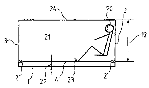
Figure 1: a cross sectian of a vehicle with
intermediate floor
Figure 2: a crass section of a vehicle with a lowered
intermediate floor
Figure 3: a basic view of the intermediate floor with
additional built-in devices
Figure 4: an anti-mine floor in the alternative
installation.
An inner compartment 21 of an armoured vehicle shown in
cross section in Figure 1 has a vehicle floor 1 or body
floor and an intermediate floor 4 provided at the distance
22 above the latter. The intermediate floor 4 is fastened,
from case to case also in an articulated manner, to the
fastening points 2 on the side walls 3. Between the
intermediate floor 4 and the housing roof 24 there is the
clearance height 12. A vehicle operator 20 supports his
feet 23 on the intermediate floor 4.
2Q In Figure 2 the intermediate floor 4 is lowered so that it
is resting substantially on the vehicle floor 1 and a
clearance height 13, which is greater than the clearance
height 12 in Figure 1, is produced between vehicle floor 1
and vehicle roof 24.
In Figure 3 the intermediate floor 4 is represented by a
mesh-like structure, which allows light 9 to pass from
below into the compartment above the intermediate floor.
Sensitive equipment 11 or other appliances 15 may be
fastened on the protective floor 4 and, depending on the
operating position of the floor, are raised or lowered
vertically with the latter. Equally, footrests 8 for
operators may be fastened on the intermediate floor 4. By
virtue of the mesh-like structure of the intermediate
floor 4 or by means of openings 18, ventilation and
deventilation as well as heating and cooling are possible
through the intermediate floor 4.

CA 02402753 2002-09-11
Figure 4 reveals how use of the protective floor is
possible also at other boundary surfaces 16 of a vehicle
and it is equally possible to design a use at boundary
surfaces 19 of a housing 17, which is adapted outside of
5 the actual vehicle inner compartment 21.
In the combat state, the intermediate floor 4 is in the
"raised" or "tensioned" position and forms the floor
surface for the crew in a vehicle compartment. In said
state, there is a distance 22 between the vehicle floor 1
and the intermediate floor 4. The intermediate floor is
functionally subdivided and made from suitable, partially
flexible material to enable it to assume the two "lowered"
or "relaxed" and "raised" or tensioned" positions,
depending on the required setting. The raised position is
preferably linked to another function in the vehicle so
that no manual intervention is needed to bring the
intermediate floor into the protective or raised position.
Said function may be e.g. "close hatch" or readiness far
action. For climbing in and out of the vehicle compartment
the lowered position of the intermediate floor is assumed
so that a greater compartment height 13 is available to the
crew. The feet 23 of the operator 20 rest on the
intermediate floor 4 so that they are protected in the
raised position of the intermediate floor against the
effect of a mine from below. The intermediate floor is
preferably brought into the raised or lowered position by
means of a suitable, non-illustrated motor drive.

CA 02402753 2002-09-11
6
List of reference characters
1 vehicle floor
2 fastening point
3 side wall
4 intermediate floor (protective floor)
5
6
7
S footrests
9 lighting
10 introduction of air
11 appliance
12 clearance height
13 clearance height
14
15 additional element
16 boundary surface
17 housing
18 openings
19 boundary surface
20 vehicle operator
21 inner compartment
22 distance
23 feet
24 housing roof

Representative Drawing
A single figure which represents the drawing illustrating the invention.
Administrative Status

2024-08-01:As part of the Next Generation Patents (NGP) transition, the Canadian Patents Database (CPD) now contains a more detailed Event History, which replicates the Event Log of our new back-office solution.

Please note that "Inactive:" events refers to events no longer in use in our new back-office solution.

For a clearer understanding of the status of the application/patent presented on this page, the site Disclaimer , as well as the definitions for Patent , Event History , Maintenance Fee  and Payment History  should be consulted.

Event History

Description Date
Inactive: Expired (new Act pat) 2022-09-12
Common Representative Appointed 2019-10-30
Change of Address or Method of Correspondence Request Received 2018-03-28
Grant by Issuance 2010-05-25
Inactive: Cover page published 2010-05-24
Pre-grant 2010-02-24
Inactive: Final fee received 2010-02-24
Notice of Allowance is Issued 2009-10-07
Letter Sent 2009-10-07
Notice of Allowance is Issued 2009-10-07
Inactive: Approved for allowance (AFA) 2009-09-15
Amendment Received - Voluntary Amendment 2009-07-23
Inactive: S.30(2) Rules - Examiner requisition 2009-01-23
Letter Sent 2007-09-04
Request for Examination Requirements Determined Compliant 2007-08-16
All Requirements for Examination Determined Compliant 2007-08-16
Request for Examination Received 2007-08-16
Inactive: IPC from MCD 2006-03-12
Application Published (Open to Public Inspection) 2003-03-14
Inactive: Cover page published 2003-03-13
Letter Sent 2003-03-12
Inactive: Single transfer 2003-01-20
Inactive: First IPC assigned 2002-11-15
Inactive: Courtesy letter - Evidence 2002-10-29
Inactive: Filing certificate - No RFE (English) 2002-10-23
Filing Requirements Determined Compliant 2002-10-23
Application Received - Regular National 2002-10-22

Abandonment History

There is no abandonment history.

Maintenance Fee

The last payment was received on 2009-08-24

Note : If the full payment has not been received on or before the date indicated, a further fee may be required which may be one of the following

  • the reinstatement fee;
  • the late payment fee; or
  • additional fee to reverse deemed expiry.

Please refer to the CIPO Patent Fees web page to see all current fee amounts.

Owners on Record

Note: Records showing the ownership history in alphabetical order.

Current Owners on Record
RHEINMETALL LANDSYSTEME GMBH
Past Owners on Record
HELLMUT PITTINGER
RALF BOTTCHER
Past Owners that do not appear in the "Owners on Record" listing will appear in other documentation within the application.
Documents

To view selected files, please enter reCAPTCHA code :


To view images, click a link in the Document Description column. To download the documents, select one or more checkboxes in the first column and then click the "Download Selected in PDF format (Zip Archive)" or the "Download Selected as Single PDF" button.

List of published and non-published patent-specific documents on the CPD .

If you have any difficulty accessing content, you can call the Client Service Centre at 1-866-997-1936 or send them an e-mail at CIPO Client Service Centre.


Document
Description 
Date
(yyyy-mm-dd) 
Number of pages   Size of Image (KB) 
Representative drawing 2002-11-15 1 6
Cover Page 2003-02-17 1 29
Abstract 2002-09-11 1 13
Description 2002-09-11 6 241
Claims 2002-09-11 3 119
Drawings 2002-09-11 3 60
Claims 2009-07-23 2 91
Description 2009-07-23 7 248
Representative drawing 2010-04-27 1 6
Cover Page 2010-04-27 1 30
Filing Certificate (English) 2002-10-23 1 161
Courtesy - Certificate of registration (related document(s)) 2003-03-12 1 130
Reminder of maintenance fee due 2004-05-12 1 109
Reminder - Request for Examination 2007-05-14 1 115
Acknowledgement of Request for Examination 2007-09-04 1 177
Commissioner's Notice - Application Found Allowable 2009-10-07 1 162
Correspondence 2002-10-23 1 24
Correspondence 2010-02-24 1 39
Prosecution correspondence 2003-01-20 1 40