Language selection

Search

Patent 2402779 Summary

Third-party information liability

Some of the information on this Web page has been provided by external sources. The Government of Canada is not responsible for the accuracy, reliability or currency of the information supplied by external sources. Users wishing to rely upon this information should consult directly with the source of the information. Content provided by external sources is not subject to official languages, privacy and accessibility requirements.

Claims and Abstract availability

Any discrepancies in the text and image of the Claims and Abstract are due to differing posting times. Text of the Claims and Abstract are posted:

  • At the time the application is open to public inspection;
  • At the time of issue of the patent (grant).
(12) Patent Application: (11) CA 2402779
(54) English Title: A RISER DEVICE
(54) French Title: COLONNE MONTANTE
Status: Deemed Abandoned and Beyond the Period of Reinstatement - Pending Response to Notice of Disregarded Communication
Bibliographic Data
Abstracts

English Abstract


A riser (18) extends between a surface vessel, e.g. a drillship (16), and an
item of subsea equipment, e.g. a blowout preventer valve (12) on the seabed
(10). The riser (18) is equipped with at least one thruster, for instance in
the form of one or more motor driven positional propellers (201, 202), which
is arranged so as to be able to exert an essentially horizontal thrust force
on the riser (18) in order to counteract the lateral forces from the oceanic
currents, so as to maintain the riser (18) in a position that corresponds to
the desired course from the surface vessel (16) to the subsea equipment (12).


French Abstract

L'invention concerne une colonne montante (18) située entre un navire de surface, un navire de forage (18), par exemple, et un article d'un équipement sous-marin, une soupape de bloc d'obturation (12), par exemple, situé sur le fond marin (10). Cette colonne montante (18) est équipée d'au moins un propulseur, sous forme d'une ou plusieurs hélices de positionnement actionnées par moteur (20¿1?, 20¿2?), conçu pour exercer une force de poussée globalement horizontale sur la colonne montante (18) afin de contrecarrer les forces latérales des courants océaniques, afin de maintenir la colonne montante (18) dans une position correspondant à un alignement désiré entre le navire de surface (16) et l'équipement sous-marin (12).

Claims

Note: Claims are shown in the official language in which they were submitted.

claims
1. A device for a riser (18) extending between subsea
equipment (12) and a surface vessel (16), including a
drilling ship, wherein at least one thruster
(20 1, 20 2) is connected to the riser (18), said thruster
(20 1, 20 2) being a prime mover capable of exerting a
transverse thrust force on the riser (18) relative to the
longitudinal direction of the riser (18).
2. A riser device according claim 1, wherein said at
least one thruster (20 1, 20 2) is provided with a position
measuring means and a thrust-regulating control means,
the position measuring means determining the position of
the thruster (20 1, 20 2) relative to an ideal riser
trajectory between said subsea equipment (12) and said
surface vessel (16), and the thrust-regulating control
means adjusting the thrust exerted on the riser (18) by
the thruster (20 1, 20 2).
3. A riser device according claim 1 or 2, wherein
said at least one thruster (20 1, 20 2) is arranged
rotatably about the longitudinal axis of the riser (18),
whereby the direction of said thrust force may be
changed.
4. A riser device according to claim 1, 2 or 3,
wherein said at least one thruster (20 1, 20 2) is
attached moveably to the riser (18), and wherein the
thruster (20 1, 20 2) is provided with at least one
auxiliary motor capable of exerting a vertical thrust
force on the thruster (20 1, 20 2) in order to move the
thruster (20 1, 20 2) vertically along the riser (18).

Description

Note: Descriptions are shown in the official language in which they were submitted.


CA 02402779 2002-09-18
WO 01/71153 PCT/NO00/00097
1
A rp_~er device
The present invention regards an arrangement for risers of
the type that extends between subsea equipment and a surface
vessel such as a drillship.
s The lower end of a riser is connected to an item of subsea
equipment, such as a blowout preventer valve or other subsea
device, and extends to for instance a drillship or a
platform, at which its upper end is attached.
When drilling or performing other operations at great depths
io using correspondingly long risers, these will be subjected to
considerable lateral forces arising from oceanic currents.
This may cause the current-affected riser to follow a
longitudinal course that may deviate substantially from a
desired ideal position curve/line, for example a straight,
is vertical line between the subsea equipment and the surface
vessel. A riser that is affected by lateral, current-
conditional forces may in some cases assume an approximately
S-shaped or spiral-like sine wave-shaped course.

CA 02402779 2002-09-18
WO 01/71153 PCT/NO00/00097
2
Even minor and moderate deviations from an ideal positioning
course in the form of an imaginary line, straight or with a
slight curvature, between the subsea equipment and the
surface vessel, may cause complications for subsea drilling
s operations and other subsea operations. Angular deviations
relative to the correct riser course between the subsea
equipment and the surface vessel are especially critical when
proximal to the subsea equipment, which may consist of a
blowout preventer valve or a wellhead. Here, to all intents
~o and purposes, no deviations exceeding three angular degrees
relative to the correct riser course, which may be assumed to
follow an ideal vertical line or curve, are tolerated.
Moreover, light is thrown on the state of the art through the
following patent publications US 4 474 129, NO 180 244 and NO
is 300 514.
According to US 4 474 129, the problem of unwanted lateral
forces that affect risers and are due to oceanic currents may
be solved by fitting streamlined bodies to the riser,
preferably at several locations along this. These known means
zo of counteracting lateral forces are specially adapted to
risers with buoyancy modules. The streamlined bodies are
removably attached to the buoyancy modules, and are able to
rotate 360° about an axis through the buoyancy modules.
NO 180 244 describes bend restricting means for flexible
zs risers, in particular risers that are integrally cast in
wellheads on the seabed. The device comprises a shell that is
disposed around the riser during the casting, and it is
especially intended to counteract bending caused by wind and
oceanic currents.

CA 02402779 2002-09-18
WO 01/71153 PCT/NO00/00097
3
NO 300 514 describes hydrodynamic elements for mounting in
several locations along a rigid riser, e.g. made from steel
and preferably with a J-configuration, which riser is
subjected to relatively high mechanical loads due to vertical
s movements in the installation or vessel on the surface. For a
J-riser, such loads are especially critical at the end and
bend portion, and the hydrodynamically acting elements are
therefore mainly arranged across this portion. The elements
are designed to give a drag effect in at least one of the
io axial directions of the riser.
By the use of simple and relatively reasonable means, an
arrangement for maintaining a desired riser position will
according to the present invention be arranged so as to keep
the positional deviation of the riser relative to an
is imaginary curve or line, within acceptable values even in
areas with considerable ocean currents.
According to the present invention, this is obtained by a
riser in conformity with the introductory part of Claim 1
being constructed in accordance with the characterising part
zo of Claim 1.
More specifically, the riser is provided with one or more
positioning organs, so called thrusters, e.g. in the form of
motor driven positioning propellers, arranged so as to impart
to the riser an essentially horizontally oriented thrust
2s force that may be varied by means of a control device
attached to each positioning organ/thruster. The present
invention presupposes that such a thruster, after being
fitted to a riser, will be able to exert a thrust force that
is transversely directed relative to the longitudinal

CA 02402779 2002-09-18
WO 01/71153 PCT/NO00/00097
4
direction of the riser, and which is substantially opposite
of the current forces act=ng on the riser.
The generation of one or more horizontal, laterally oriented
thrust forces by the positioning organ or organs, which
s forces may be acting in mutually contradictory directions,
will seek to counteract the force of the oceanic currents
acting on the riser within the layer of water in which the
positioning organ is located, and by so doing keep the riser
positioned relative to the ideal course from the surface
~o vessel to the subsea equipment. In the case of two or more
vertically staggered positioning organs, and where different
currents with mutually contradictory flow directions occur in
different layers of water, it is the positioning
organ/thruster within each respective layer of water that
~s opposes the lateral forces acting on the riser at that depth.
Thus, according to a preferred embodiment, each positioning
organ/thruster is provided with a position measuring system
designed to determine the position of the thruster in
relation to an imaginary line/curve between the equipment on
zo the seabed and the surface vessel. As mentioned, each
thruster is provided with a control device that is designed
to adjust the thrust force of each thruster relative to the
adjacent portion of the riser, which portion constitutes the
mounting element for the respective thruster, for the purpose
zs of making the riser assume/maintain a desired position,
independently of the influence of lateral forces due to
oceanic currents. When using several thrusters, these act in
concert to perform this task, regardless of whether oceanic
currents in different layers of water have mutually
3o contradictory flow directions, each thruster preferably being
rotatable about the axis of the riser.

WO 01/71153 cA 02402779 2002-09-18 pCT/NO00/00097
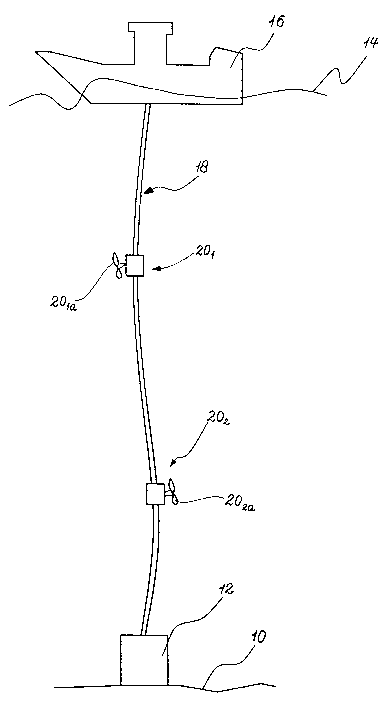
A non-limiting example of an embodiment is illustrated
schematically in the only figure of the accompanying drawing.
The figure shows a schematic side view of a surface vessel
and an item of subsea equipment, together with a riser
s extending between the surface vessel and said equipment.
In the figure, reference number 10 denotes the seabed and 12
denotes an item of subsea equipment in the form of a blowout
preventer valve.
Reference number 14 denotes the surface of the sea, while 16
io indicates a surface vessel, e.g. a drillship.
Between the surface vessel 16 and the subsea equipment 12, a
riser 18 extends in the normal fashion, following a slightly
curved, vertical course. It is normally understood that the
riser must not deviate from the desired vertical course by
~s more than three angular degrees in the area of the blowout
preventer valve.
In order to be able to maintain the riser in at least an
approximately vertical, correct position, it has in the
example of an embodiment, according to the invention, been
zo fitted with two thrusters 201 and 20z each in the form of a
motor driven positioning propeller, the actual propeller
being indicated by 20,a and 20za respectively. In order for
such a thruster to function satisfactorily for realisation of
the objective of the invention, it must be able to impart to
zs the riser 18 a thrust force that is transversely oriented
relative to the longitudinal direction of the riser, which
force is directed against the flow direction of the oceanic
current in the relevant layer of water.

CA 02402779 2002-09-18
WO 01/71153 PCT/NO00/00097
6
For illustrative purposes, the propellers 201a and 202a of the
two thrusters 201 and 202 respectively have been oriented in
opposing directions, however this represents a special case
in which two oceanic currents that are present at different
s depths have opposing directions of flow. Thus, the direction
in which the force applied by each thruster acts with regard
to the riser, must be adjustable. It is assumed that this
adjustment of the desired direction of thrust and depth
positioning is carried out in advance, however solutions may
~o also be envisaged in which the thrusters 201, 20z, for
example through the use of racks (not shown) attached to the
riser 18 and hydraulic motors (not shown) attached to the
thrusters 201, 202, are movable in the vertical plane. Such
vertical displacement, and possibly rotation, will in that
is case be controllable from the surface vessel 16.
A control system that is known per se, and which is not
shown, must be provided for each thruster and be arranged so
as to be able to vary the magnitude of the thrust of the
respective thrusters, among other things in relation to the
Zo prevailing oceanic current conditions in the relevant layer
of water.

Representative Drawing
A single figure which represents the drawing illustrating the invention.
Administrative Status

2024-08-01:As part of the Next Generation Patents (NGP) transition, the Canadian Patents Database (CPD) now contains a more detailed Event History, which replicates the Event Log of our new back-office solution.

Please note that "Inactive:" events refers to events no longer in use in our new back-office solution.

For a clearer understanding of the status of the application/patent presented on this page, the site Disclaimer , as well as the definitions for Patent , Event History , Maintenance Fee  and Payment History  should be consulted.

Event History

Description Date
Application Not Reinstated by Deadline 2006-03-20
Time Limit for Reversal Expired 2006-03-20
Inactive: Abandon-RFE+Late fee unpaid-Correspondence sent 2005-03-21
Deemed Abandoned - Failure to Respond to Maintenance Fee Notice 2005-03-21
Letter Sent 2003-03-18
Inactive: Single transfer 2003-01-28
Inactive: Courtesy letter - Evidence 2003-01-21
Inactive: Cover page published 2003-01-17
Inactive: Notice - National entry - No RFE 2003-01-15
Application Received - PCT 2002-10-22
National Entry Requirements Determined Compliant 2002-09-18
Application Published (Open to Public Inspection) 2001-09-27

Abandonment History

Abandonment Date Reason Reinstatement Date
2005-03-21

Maintenance Fee

The last payment was received on 2004-02-13

Note : If the full payment has not been received on or before the date indicated, a further fee may be required which may be one of the following

  • the reinstatement fee;
  • the late payment fee; or
  • additional fee to reverse deemed expiry.

Please refer to the CIPO Patent Fees web page to see all current fee amounts.

Fee History

Fee Type Anniversary Year Due Date Paid Date
Basic national fee - standard 2002-09-18
MF (application, 2nd anniv.) - standard 02 2002-03-20 2002-09-18
Registration of a document 2003-01-28
MF (application, 3rd anniv.) - standard 03 2003-03-20 2003-02-10
MF (application, 4th anniv.) - standard 04 2004-03-22 2004-02-13
Owners on Record

Note: Records showing the ownership history in alphabetical order.

Current Owners on Record
NATIONAL OILWELL NORWAY AS
Past Owners on Record
JON GRUDE GJEDEBO
Past Owners that do not appear in the "Owners on Record" listing will appear in other documentation within the application.
Documents

To view selected files, please enter reCAPTCHA code :


To view images, click a link in the Document Description column. To download the documents, select one or more checkboxes in the first column and then click the "Download Selected in PDF format (Zip Archive)" or the "Download Selected as Single PDF" button.

List of published and non-published patent-specific documents on the CPD .

If you have any difficulty accessing content, you can call the Client Service Centre at 1-866-997-1936 or send them an e-mail at CIPO Client Service Centre.


Document
Description 
Date
(yyyy-mm-dd) 
Number of pages   Size of Image (KB) 
Representative drawing 2002-09-18 1 6
Cover Page 2003-01-17 2 34
Abstract 2002-09-18 2 56
Drawings 2002-09-18 1 8
Description 2002-09-18 6 216
Claims 2002-09-18 1 40
Notice of National Entry 2003-01-15 1 188
Courtesy - Certificate of registration (related document(s)) 2003-03-18 1 130
Reminder - Request for Examination 2004-11-23 1 116
Courtesy - Abandonment Letter (Request for Examination) 2005-05-30 1 166
Courtesy - Abandonment Letter (Maintenance Fee) 2005-05-16 1 174
PCT 2002-09-18 8 353
Correspondence 2003-01-15 1 24
Fees 2003-02-10 1 30
Fees 2004-02-13 1 31