Language selection

Search

Patent 2402905 Summary

Third-party information liability

Some of the information on this Web page has been provided by external sources. The Government of Canada is not responsible for the accuracy, reliability or currency of the information supplied by external sources. Users wishing to rely upon this information should consult directly with the source of the information. Content provided by external sources is not subject to official languages, privacy and accessibility requirements.

Claims and Abstract availability

Any discrepancies in the text and image of the Claims and Abstract are due to differing posting times. Text of the Claims and Abstract are posted:

  • At the time the application is open to public inspection;
  • At the time of issue of the patent (grant).
(12) Patent: (11) CA 2402905
(54) English Title: VIEWING PLATFORM FOR A WIND ENERGY PLANT
(54) French Title: UNE PLATE-FORME D'OBSERVATION POUR EOLIENNE
Status: Expired and beyond the Period of Reversal
Bibliographic Data
(51) International Patent Classification (IPC):
  • A01M 31/02 (2006.01)
  • E04G 03/00 (2006.01)
  • E04G 03/24 (2006.01)
  • E04H 01/12 (2006.01)
(72) Inventors :
  • ALOYS WOBBEN, (Germany)
(73) Owners :
  • ALOYS WOBBEN
(71) Applicants :
  • ALOYS WOBBEN (Germany)
(74) Agent: OYEN WIGGS GREEN & MUTALA LLP
(74) Associate agent:
(45) Issued: 2006-07-25
(86) PCT Filing Date: 2000-11-28
(87) Open to Public Inspection: 2001-09-20
Examination requested: 2003-01-10
Availability of licence: N/A
Dedicated to the Public: N/A
(25) Language of filing: English

Patent Cooperation Treaty (PCT): Yes
(86) PCT Filing Number: PCT/EP2000/011867
(87) International Publication Number: EP2000011867
(85) National Entry: 2002-09-13

(30) Application Priority Data:
Application No. Country/Territory Date
200 04 822.8 (Germany) 2000-03-17

Abstracts

English Abstract


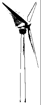
A wind power installation comprising a rotor which is coupled to a
generator within a machine housing atop a pylon, characterised in that an
observation platform is arranged below the machine housing on the pylon and is
fixed by means of a support structure to the pylon, wherein the support
structure comprises upper and lower carrier arrangements, wherein each carrier
arrangement comprises a plurality of substantially identically formed support
arms which are distributed around the periphery of the pylon, that the
observation platform substantially completely surrounds the pylon, that the
upper carrier arrangement carries a roof of the observation platform, that the
lower carrier arrangement carries a floor of the observation platform, that
the
upper and lower carrier arrangements receive holding means for windows which
are distributed over the periphery of the observation platform and permit the
user of the observation platform to have a panoramic view over the landscape.


French Abstract

L'invention concerne une éolienne comportant un rotor couplé à un générateur à l'intérieur d'une nacelle. Ces types d'éoliennes, par exemple les types E-40, E-66 de la société Enercon à Aurich, sont connus depuis longtemps. L'invention vise à améliorer les possibilités de visite d'une éolienne de façon à permettre à un plus grand nombre de personnes de visiter de telles installations. L'éolienne selon l'invention, comprenant un rotor couplé à un générateur à l'intérieur d'une nacelle, est caractérisée en ce qu'une plate-forme panoramique est placée sous la nacelle, sur la tour de l'éolienne, à laquelle elle est fixée au moyen d'une structure portante. Cette dernière est constituée d'un ensemble porteur supérieur et d'un ensemble porteur inférieur, comprenant chacun plusieurs bras de support pratiquement identiques, répartis sur la périphérie de la tour. Cette plate-forme entoure pratiquement la totalité de la tour. La structure portante supérieure supporte le toit de la plate-forme tandis que la structure portante inférieure reçoit le fond de la plate-forme. Les deux structures portantes reçoivent des fixations pour des fenêtres qui sont réparties sur la périphérie de la plate-forme et permettent à l'utilisateur de la plate-forme de bénéficier d'une vue panoramique sur la région.

Claims

Note: Claims are shown in the official language in which they were submitted.


CLAIMS
1. A wind power installation comprising a pylon and a machine
housing arranged on top of the pylon, wherein an observation platform is
arranged below the machine housing at the pylon and is fixed by means of a
support structure to the pylon, wherein the support structure comprises an
upper carrier arrangement and a lower carrier arrangement, wherein each
carrier arrangement comprises a plurality of substantially identically formed
support arms which are distributed around the periphery of the pylon, wherein
the observation platform substantially completely surrounds the pylon, wherein
the upper carrier arrangement carries a roof of the observation platform,
wherein the lower carrier arrangement carries a floor of the observation
platform, wherein the upper and the lower carrier arrangements receive holding
means for windows which are distributed over the periphery of the observation
platform and permit the user of the observation platform, in use of the
observation platform, to have a panoramic view over the landscape, wherein
the support arms of the upper carrier arrangement are longer than the support
arms of the lower carrier arrangement,
wherein the support arms are screwed and/or welded to the pylon,
wherein the pylon in the region of the observation platform comprises at least
one of steel, concrete and reinforced concrete, wherein the access to the
observation platform comprises a ladder, a stairway or an elevator within the
pylon.
2. A wind power installation as set forth in claim 1 characterised in
that the lower and the upper carrier arrangement respectively comprise twelve
support arms, wherein associated with an upper support arm vertically
therebeneath is a lower support arm.
5

3. A wind power installation as set forth in any one of claims 1 and 2
characterised in that the spacing between the observation platform and the
machine housing of the wind power installation is less than the spacing
between a rotor blade tip and a rotor blade hub.
4. A wind power installation as set forth in any one of claims 1 and 2
characterised in that the spacing of the observation platform relative to the
machine housing is greater than the spacing between a rotor blade tip and a
rotor blade hub.
5. A wind power installation as set forth in any one of claims 1
through 4 characterised in that the windows of the observation platform are so
inclined that the upper edge of the windows is further away from the pylon
than
the lower edge.
6. A wind power installation as set forth in any one of claims 1
through 5 characterised in that the observation platform is mounted rotatably
about the pylon and is rotatable preferably by a motor drive about the pylon.
7. A wind power installation as set forth in any one of claims 1
through 6 characterised in that the observation platform has acoustic sound
insulation which substantially prevents the penetration of external noise into
the
observation platform, in particular the noise produced by the wind power
installation.
8. A wind park comprising a plurality of wind power installations,
wherein one of those wind power installations is fitted with an observation
platform as set forth in any one of claims 1 through 7 and said installation
with
the observation platform is enclosed within the wind park by a plurality of
wind
power installations.
6

9. A wind park in particular as set forth in claim 8 characterised in
that the wind power installation with the observation platform is so arranged
within the wind park that the majority of wind power installations of the wind
park and preferably each wind power installation of the wind park is to be
seen
from the observation platform.
10. Use of a wind power installation with an observation platform as
set forth in any one of claims 1 through 7 as a fire observation tower.
7

Description

Note: Descriptions are shown in the official language in which they were submitted.


CA 02402905 2004-07-23
VIEWING PLATFORM FOR A WIND ENERGY PLANT
The invention concerns a wind power installation comprising a rotor which is
coupled
to a generator within a machine housing. Such wind power installations have
already long
been known, for example the wind power installations have types E-40 and E-66
from
Enercon, Aurich.
Wind power installations and in particular wind parks with a large number of
wind
power installations have in the meantime been technically developed to such an
extent that
they make a relevant contribution to electrical energy production. It is
precisely wind parks
and relatively large individual installations that impressive structures which
readily lend
themselves as the object of sightseeing tours, especially as wind power
represents an
interesting technology which arouses interest in very large numbers of people.
The object of the invention is to improve sightseeing options of a wind power
installation, in which respect more people than previously can view such wind
power
installations.
In accordance with the invention that obj ect is attained by a wind power
installation
having the features of claim 1. The advantageous development thereof is set
forth in the
appendant claims.
The wind power installation according to the invention is provided with an
observation platform which is arranged beneath the machine housing on the
pylon of the wind
power installation. The observation platform is fixed directly to the pylon
and comprises an
upper Garner arrangement comprising a plurality of support arms and a lower
carrier
arrangement, also comprising support arms. Access to the observation platform
can be by
way of ladders, stairs or elevators in or on the pylon.

CA 02402905 2002-09-13
The observation platform according to the invention is extremely
attractive for visitors to wind power installations, in particular visitors to
wind parks, because it not only permits viewing of an individual installation
or a plurality of installations from the worm's-eye view, but also guarantees
a view from approximately hub height (machine housing height) and thus,
particularly in regions without hills and mountains, a highly attractive
landscape perspective as well as the possibility of viewing the wind power
installation. In accordance with the invention, a closed structure is provided
for the observation platform, that is to say the entire observation platform
is closed by glass walls and roofs and thus a visit to the observation
platform is still pleasant even when it is very windy and very cold.
In order to have a good outlook from the observation platform it is
preferably arranged directly beneath the machine housing so that the rotor
blades move past the observation platform in operation under the effect of
wind force. It is however also certainly possible for the observation
platform to be mounted to the pylon in such a way that it is always beneath
the rotor.
The invention is described hereinafter by means of an example
illustrated in greater detail in the drawing in which:
Figure 1 shows a top view on to and a view into an observation
platform,
Figure 2 shows a view in cross-section through the support structure
of the observation platform, and
Figure 3 shows a view of a wind power installation with an
observation platform.
Figure 1 shows the pylon 1 of a wind power installation to which an
observation platform 2 is fixed. The observation platform comprises a
support structure, comprising an upper carrier arrangement 3 with a
plurality of support arms 4 and a lower carrier arrangement (see Figure 2),
also with a plurality of support arms. In this case, associated with a support
arm on the upper carrier arrangement, vertically therebeneath, is a
respective support arm of the lower carrier arrangement, and the support
arms which are disposed vertically one above the other are connected by
2

CA 02402905 2002-09-13
means of connecting portions 5. Provided between the connecting portions
are glass walls which permit a view out of the observation platform. The
lower carrier arrangement carries the floor of the observation platform
while the upper carrier arrangement carries the roof, in particular
consisting of transparent material. Adjacent support arms of the upper
carrier arrangement (like also adjacent support arms of the lower carrier
arrangement) are also connected together by connecting portions 6. The
support arms comprise a double-T-profile iron member and are screwed to
the pylon which preferably comprises steel.
Figure 2 is a view in cross-section showing the carrier structure of
the observation platform 2. The upper carrier arrangement 3 and the lower
carrier arrangement 6 can be seen here. In the illustrated example each
carrier arrangement comprises twelve support arms 4 which are distributed
uniformly around the periphery. The support arms of the upper carrier
arrangement are longer in this case (that is to say their tip is further away
from the pylon) than the length of the support arms of the lower carrier
arrangement. That makes it possible for the windows to be provided in the
observation platform in an inclined position in such a way that it is possible
for the user also to have a view directly on to the ground if the floor itself
is
not already made from transparent material, for example glass.
Access to the observation platform which embraces the entire pylon
is through an opening in the pylon wall. It is possible in that way to provide
an elevator within the pylon so that users can comfortably and conveniently
reach the observation platform with the elevator.
The size of the observation platform is such that only a limited
number of people can stay there so that the stability and the safe mounting
of the observation platform are also guaranteed at any time. To reinforce
the mounting of the support arms, the support arms can be welded to the
pylon or it is also possible to provide further holding means.
If the roof of the observation platform is made from transparent
material, for example glass, it is possible for the user of the observation
platform also to observe the machine housing and the rotor with its rotor
blades above the observation platform.
3

CA 02402905 2002-09-13
To provide better information the observation platform can also be
equipped with measuring devices which provide the user of the observation
platform with further data about the wind power installation itself or other
wind power installations. Such data can also be the wind data at various
locations of the wind power installation, as well as power data and so forth.
If such a wind power installation is disposed in a wind park it is
highly attractive for the wind power installation to be so disposed within the
wind park that all wind power installations of the wind park can be
observed from the observation platform.
The entire observation platform can be provided with sound
insulation so that external noise and in particular the noise of the wind
power installation penetrates into the observation platform only to a slight
degree, so that a conversation is also readily possible there. It will be
appreciated that it can also be provided, so that the visitor to the
observation platform enjoys conditions which are as real as possible, that
there are no sound insulating measures whatsoever, so that the wind which
whistles past at the height of the observation platform, like also the noise
of the wind power installation and the parts thereof (in particular the
generator) can be readily heard on the observation platform.
Instead of being statically fixed to the pylon the observation platform
can also be mounted rotatably about the pylon, for which purpose a motor
drive is then provided for rotating the observation platform around the
pylon.
The observation platform of the wind power installation can also be
used for fire observation purposes. In that case the structure according to
the invention represents an extremely inexpensive structure which does not
require the separate erection of a fire observation tower. As in the
meantime many wind power installations are also being set up at inland
sites, a wind power installation according to the invention permits highly
efficient fire observation in the hot season.
4

Representative Drawing
A single figure which represents the drawing illustrating the invention.
Administrative Status

2024-08-01:As part of the Next Generation Patents (NGP) transition, the Canadian Patents Database (CPD) now contains a more detailed Event History, which replicates the Event Log of our new back-office solution.

Please note that "Inactive:" events refers to events no longer in use in our new back-office solution.

For a clearer understanding of the status of the application/patent presented on this page, the site Disclaimer , as well as the definitions for Patent , Event History , Maintenance Fee  and Payment History  should be consulted.

Event History

Description Date
Time Limit for Reversal Expired 2019-11-28
Common Representative Appointed 2019-10-30
Letter Sent 2018-11-28
Inactive: IPC expired 2016-01-01
Grant by Issuance 2006-07-25
Inactive: Cover page published 2006-07-24
Inactive: Final fee received 2006-05-10
Pre-grant 2006-05-10
Notice of Allowance is Issued 2006-03-22
Letter Sent 2006-03-22
Notice of Allowance is Issued 2006-03-22
Inactive: IPC from MCD 2006-03-12
Inactive: Approved for allowance (AFA) 2006-03-09
Amendment Received - Voluntary Amendment 2005-06-23
Inactive: S.30(2) Rules - Examiner requisition 2004-12-23
Amendment Received - Voluntary Amendment 2004-07-23
Inactive: S.30(2) Rules - Examiner requisition 2004-02-02
Inactive: IPC assigned 2004-01-23
Amendment Received - Voluntary Amendment 2003-10-22
Inactive: S.30(2) Rules - Examiner requisition 2003-04-22
Letter sent 2003-03-03
Advanced Examination Determined Compliant - paragraph 84(1)(a) of the Patent Rules 2003-03-03
Letter Sent 2003-02-27
Inactive: Cover page published 2003-01-14
Inactive: Notice - National entry - No RFE 2003-01-10
Inactive: Applicant deleted 2003-01-10
Inactive: Inventor deleted 2003-01-10
Request for Examination Requirements Determined Compliant 2003-01-10
Inactive: Advanced examination (SO) fee processed 2003-01-10
All Requirements for Examination Determined Compliant 2003-01-10
Request for Examination Received 2003-01-10
Inactive: Advanced examination (SO) 2003-01-10
Application Received - PCT 2002-10-23
National Entry Requirements Determined Compliant 2002-09-13
Application Published (Open to Public Inspection) 2001-09-20

Abandonment History

There is no abandonment history.

Maintenance Fee

The last payment was received on 2005-09-21

Note : If the full payment has not been received on or before the date indicated, a further fee may be required which may be one of the following

  • the reinstatement fee;
  • the late payment fee; or
  • additional fee to reverse deemed expiry.

Patent fees are adjusted on the 1st of January every year. The amounts above are the current amounts if received by December 31 of the current year.
Please refer to the CIPO Patent Fees web page to see all current fee amounts.

Owners on Record

Note: Records showing the ownership history in alphabetical order.

Current Owners on Record
ALOYS WOBBEN
Past Owners on Record
None
Past Owners that do not appear in the "Owners on Record" listing will appear in other documentation within the application.
Documents

To view selected files, please enter reCAPTCHA code :


To view images, click a link in the Document Description column. To download the documents, select one or more checkboxes in the first column and then click the "Download Selected in PDF format (Zip Archive)" or the "Download Selected as Single PDF" button.

List of published and non-published patent-specific documents on the CPD .

If you have any difficulty accessing content, you can call the Client Service Centre at 1-866-997-1936 or send them an e-mail at CIPO Client Service Centre.


Document
Description 
Date
(yyyy-mm-dd) 
Number of pages   Size of Image (KB) 
Representative drawing 2002-09-12 1 8
Abstract 2003-10-21 1 26
Description 2003-10-21 4 198
Claims 2003-10-21 3 106
Abstract 2002-09-12 1 38
Drawings 2002-09-12 3 69
Description 2002-09-12 4 197
Claims 2002-09-12 3 102
Description 2004-07-22 4 193
Claims 2004-07-22 3 101
Claims 2005-06-22 3 92
Representative drawing 2006-07-03 1 5
Notice of National Entry 2003-01-09 1 189
Acknowledgement of Request for Examination 2003-02-26 1 185
Commissioner's Notice - Application Found Allowable 2006-03-21 1 162
Maintenance Fee Notice 2019-01-08 1 181
PCT 2002-09-12 22 740
PCT 2002-09-13 2 91
Correspondence 2006-05-09 1 31
Fees 2009-11-17 2 124