Language selection

Search

Patent 2403223 Summary

Third-party information liability

Some of the information on this Web page has been provided by external sources. The Government of Canada is not responsible for the accuracy, reliability or currency of the information supplied by external sources. Users wishing to rely upon this information should consult directly with the source of the information. Content provided by external sources is not subject to official languages, privacy and accessibility requirements.

Claims and Abstract availability

Any discrepancies in the text and image of the Claims and Abstract are due to differing posting times. Text of the Claims and Abstract are posted:

  • At the time the application is open to public inspection;
  • At the time of issue of the patent (grant).
(12) Patent Application: (11) CA 2403223
(54) English Title: MOLDING APPARATUS WITH EXTERNAL MOLD BLOCK COOLING
(54) French Title: DISPOSITIF DE MOULAGE A REFROIDISSEMENT EXTERNE DU BLOC DE MOULAGE
Status: Deemed Abandoned and Beyond the Period of Reinstatement - Pending Response to Notice of Disregarded Communication
Bibliographic Data
(51) International Patent Classification (IPC):
  • B29C 33/04 (2006.01)
  • B29C 33/36 (2006.01)
  • B29C 35/16 (2006.01)
(72) Inventors :
  • LUPKE, MANFRED A. A. (Canada)
  • LUPKE, STEFAN A. (Canada)
(73) Owners :
  • MANFRED A. A. LUPKE
  • STEFAN A. LUPKE
(71) Applicants :
  • MANFRED A. A. LUPKE (Canada)
  • STEFAN A. LUPKE (Canada)
(74) Agent: DENNISON ASSOCIATES
(74) Associate agent:
(45) Issued:
(22) Filed Date: 2002-09-11
(41) Open to Public Inspection: 2004-03-11
Examination requested: 2002-09-11
Availability of licence: N/A
Dedicated to the Public: N/A
(25) Language of filing: English

Patent Cooperation Treaty (PCT): No

(30) Application Priority Data: None

Abstracts

English Abstract


A mold block for use with other mold blocks in
forming a moving mold tunnel of a plastic molding
apparatus has front and rear surfaces which face in
direction of travel of the mold block and opposite side
surfaces between the front and rear surfaces. Each of
the side surfaces of the mold block includes a closed
sided open ended channel which extends across the side
surface to form a passage to receive a cooling medium to
be fed into the passage for cooling of the mold block.


Claims

Note: Claims are shown in the official language in which they were submitted.

-10-
THE EMBODIMENTS OF THE INVENTION IN WHICH AN EXCLUSIVE
PROPERTY OR PRIVILEGE IS CLAIMED ARE DEFINED AS FOLLOWS:
1. A mold block for use with other mold blocks in
forming a moving mold tunnel of a plastic molding
apparatus, said mold block having front and rear surfaces
which face direction of travel for the mold block and
having a first side surface between said front and rear
surfaces, said mold block including a closed sided open
ended channel which extends at least substantially across
said side surface of said mold block, said channel
forming passage to receive a cooling medium to be fed
into said passage for cooling of the mold block.
2. A mold block as claimed in Claim 1 wherein said
channel extends in a direction vertically across said
first side surface of said mold block.
3. A mold block as claimed in Claim 2 wherein said
channel has a labyrinth construction formed by a
plurality of channel parts which are reversed in flow
direction between adjacent ones of said channel parts.
4. A mold block as claimed in Claim 3 wherein said
channel parts comprise a primary channel part and at
least one secondary channel part, the primary channel
part being located adjacent the side surface of the mold
block and receiving the cooling medium from a source of
the cooling medium, the at least one secondary channel
part being located radially outwardly of the primary
channel part and receiving the cooling medium from the
primary channel part.
5. A mold block as claimed Claim 2 where said channel
has a first end opening outside of said mold block and a
second end which opens into said mold block and which is

-11-
connected to a source of a vacuum within and operating
other functions of said mold block, the cooling medium
being drawn through the channel by the source of vacuum.
6. A mold block as claimed in Claim 2 wherein said
channel has first and second ends both of which open
outside of the mold block, the cooling medium being
forced by a positive pressure source through the channel.
7. A mold block as claimed in Claim 1 wherein said
channel extends horizontally across said side surface of
said mold block.
8. A mold block as claimed in Claim 7 wherein said
channel comprises one of a plurality of channels on said
side surface of said mold block, said plurality of
channels lying side by side with one another in
horizontal rows across the side surface of said mold
blocks.
9. A mold block as claimed in Claims 2 or 8 wherein
said mold block has a second side surface provided with
another closed sided open ended channel to receive the
cooling medium.

Description

Note: Descriptions are shown in the official language in which they were submitted.


CA 02403223 2002-09-11
- 1 -
MOLDING APPARATUS WITH EXTERNAL MOLD BLOCK COOLING
FIELD OF THE INVENTION
The present invention relates to the cooling of
mold blocks in a moving mold tunnel of a plastic molding
apparatus.
BACKGROUND OF THE INVENTION
In a plastic molding apparatus it is extremely
important to provide cooling of mold blocks of a moving
mold tunnel as the mold blocks are in the product forming
stage. The cooling of the mold blocks provides
substantial benefits to the product itself.
One example of a molding apparatus using a moving
mold tunnel is a plastic pipe mold. It is known with
existing pipe molds to provide internal cooling of the
mold blocks as they move through the mold tunnel. In
some cases, this internal cooling is provided by chilled
water. Controlling the flow of the water to prevent
drippage from the molding apparatus can be quite
difficult.
Internal cooling of mold blocks is also provided
by means of a chilled gas. This necessitates specific
internal machining of the mold blocks. This is expensive
and makes it extremely difficult to retrofit the mold
blocks to include cooling capacity.
Some attempts have been made to provide external
cooling of the mold blocks while they are in the mold
tunnel. These attempts involve the flowing of cooling
air lengthwise of the mold tunnel to the outside of the
mold blocks. However, according to conventional practice

CA 02403223 2002-09-11
- 2 -
there is no way of ensuring that the cooling air is
maintained in contact with the mold blocks. It is simply
free to flow outwardly away from the mold blocks rather
than being contained at the surface of the mold blocks.
SUN~1ARY OF THE PRESENT INVENTION
The present invention relates to a method of
providing cooling to the exterior surface of a mold block
and more specifically to a mold block adapted for the
exterior cooling. The cooling method of the present
invention does not necessitate internal mold block
machining and does allow retrofitting of existing mold
blocks with the cooling features of the present
invention.
More specifically, according to the present
invention a mold block for use with other mold blocks in
forming a moving mold tunnel of a plastic molding
apparatus has front and rear surfaces which face
direction of travel for the mold block. The mold block
further has a side surface between the front and rear
surfaces of the mold block. The mold block includes a
closed sided open ended channel which extends at least
substantially across the side surface of the mold block.
The channel provides a controlled flow passage for a
cooling medium, preferably a cooling gas to be fed to and
remain in intimate contact with the mold block.
In one embodiment of the invention the channel
extends vertically of the mold block. In another
embodiment of the invention the channel extends
horizontally of the mold block.
By providing the channel along the side surface of
the mold block each mold block can be cooled individually

CA 02403223 2002-09-11
- 3 -
of every other mold block or the mold blocks can be
cooled as a group along the mold tunnel. In all cases
the cooling medium is contained in a manner to maximize
the cooling benefits of the cooling medium. Furthermore,
existing mold blocks without the cooling features of the
present invention can be retrofitted to include a side
mounted cooling channel.
BRIEF DESCRIPTION OF THE DRAWINGS
The above as well as other advantages and features
of the present invention will be described in greater
detail according to the preferred embodiments of the
present invention in which;
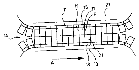
Figure 1 is a schematic view of a pipe molding
apparatus including mold blocks provided with cooling
features according to a preferred embodiment of the
present invention;
Figure 2 is an enlarged schematic view through the
moving mold tunnel of the molding apparatus of Figure 1;
Figure 3 is a front view of one of the mold blocks
from the moving mold tunnel of Figure 2;
Figure 4 is a front view of a further mold block
modified from the mold block of Figure 3 according to
another preferred embodiment of the present invention;
and
Figure 5 is a front view of a mold block according
to still a further preferred embodiment of the present
invention.
DETAILED DESCRIPTION ACCORDING TO THE PREFERRED

CA 02403223 2002-09-11
- 4 -
EMBODIMENTS OF THE PRESENT INVENTION IN WHICH:
Figure 1 shows a pipe molding apparatus generally
indicated at 1. This apparatus includes an extruder 3
which delivers molten plastic through a die 5 to a
plastic corrugator generally indicated at 7. The plastic
corrugator comprises an upper endless train 11 of mold
block sections and a lower endless train 13 of mold block
sections. The mold block sections on the upper and lower
trains come together along a moving mold tunnel 14 which
receives the molten plastic to shape a plastic pipe 9
which comes out the downstream end of the mold tunnel.
Figure 2 shows the mold block sections 17 mounted
by mold block carriers 15 to the upper train 11 of the
mold blocks. Mold block sections 21 are mounted by
carriers 19 to the lower train 13 of the corrugator. The
mold block sections from the upper and lower trains or
loops move in the direction of arrow A through the mold
tunnel 14. Each of the mold block sections as indicated
by mold block sections 17 in Figure 2 has a front face F
and a rear face R both of which face in the direction of
travel of the mold blocks through the mold tunnel.
An air plenum 23 extends along the length of the
mold tunnel. The purpose of this air plenum will be
described later in detail.
Figure 3 of the drawings shows the front face of
one of the mold blocks formed from upper mold block
section 17 and lower mold block section 21. The upper
mold block section has a parting face 18 which joins with
the parting face 22 of the lower mold block section to
form a completely closed mold block. The two mold block
sections define an interior pipe forming mold region 24.
The pipe formed in this molding region can be shaped by

CA 02403223 2002-09-11
- 5 -
either vacuum drawn through small slits in the mold block
section or by blow molding which introduces positive air
pressure to the pipe formed in the molding region 24.
Figure 3 shows that the mold block has first and
second side surfaces S to its opposite sides between the
front and rear surfaces of the mold block. A cooling
system generally indicated at 31 is fitted to each of the
side surfaces of the mold block.
In the Figure 3 embodiment cooling system 31
comprises a labyrinth channel comprising a primary
channel part 43 and secondary channel parts 47 and 51.
As can be seen in Figure 3 channel part 47 reverses in
direction relative to channel part 43 at the mouth 45
between the two channel parts. Channel 51 reverses in
direction relative to channel part 47 at the mouth 49
between the two channel parts.
The primary channel part 43 has an open mouth 41
which enters between the closed sides of channel part. 43.
One of those sides in defined by a pair of mounting
plates 33 and 34 secured directly to the side surface of
the mold block. The other side is defined by plate 35
which runs downwardly to the mouth 45 between the primary
channel part 43 and the secondary channel part 47.
The secondary channel part 47 is defined by plate
on its one side and plate 37 on its other side. Plate
30 37 terminates short of the channel mouth 49 so that the
other secondary channel part 51 is defined by plate 37 on
its one side and plate 39 on its other or outer side.
The outside secondary channel part 51 in the
35 embodiment shown in Figure 3 turns inwardly to a short
horizontally extending channel part 53 terminating with a

CA 02403223 2002-09-11
- 6 -
channel outlet mouth 55. This channel mouth opens to the
inside of the mold block and connects with vacuum lines
57 and 59 which are in turn connected with a main vacuum
line 61.
As will be seen from the description above the
labyrinth of channel parts as described comprises a
plurality of close sided open ended channel parts which
extend vertically to opposite sides of the mold block.
As earlier noted, an air plenum 23 runs along the
length of the mold block tunnel. As each of the mold
blocks moves through the tunnel it is fed with cooled air
from the plenum 23 with that cooled air being fed into
the channel labyrinth through the open mouth 41 of the
primary channel 43. This channel which is the closest
channel part to the side surface of the mold block
receives the coldest air. This is where the air has the
greatest cooling effect on the mold block.
The air although somewhat slightly warmed by the
initial cooling while moving through channel part 43 is
then reversed in direction up through channel part 47 and
further reversed in direction downwardly through channel
part 51. The air at this point although warmer than when
it initially entered channel part 43 is still cooler than
the outside air around the mold block and still has a
cooling effect on the mold block.
In the embodiment shown in Figure 3 the cooling
air is drawn by vacuum into the cooling labyrinth. This
vacuum is one which is used to control other functions of
the mold blocks such as vacuum forming of the product
and/or internal vacuum cooling of the mold block. The
vacuum as earlier noted is drawn from the main vacuum
line 61 through the channels 57 and 59 which connect

CA 02403223 2002-09-11
_ 7 _
directly to the outlet end 55 of the channel labyrinth
31.
It is to be noted from Figure 3 that the channel
labyrinth 31 is easily adapted for retrofitting to an
existing mold block not having the exterior mold cooling
features. The two plate parts 33 and 34 secured directly
to the outside side surface of the mold block. These
plate parts separate from one another for opening and
closing of the two mold block sections.
From the description above, it should be seen how
individual mold block continues to receive cooling air
which is trapped at the opposite side surfaces of the
mold block as the mold block moves through the mold
tunnel.
Figure 4 of the drawings shows a mold block formed
by an upper mold block section 65 and a lower mold block
section 67. A channel labyrinth generally indicated at 71
is mounted to each of the side surfaces of the mold block
formed by sections 65 and 67.
In this embodiment the entrance to the labyrinth
is through a mouth 75 leading to primary channel part 77.
The outlet from the labyrinth is through a channel mouth
79 from a secondary channel part 81. An internal mouth
80 is provided between the channel parts 75 and 79. The
flow of cooling air into the labyrinth therefore enters
through the mouth 75, runs along primary channel part 77
and reverses through internal channel mouth along channel
part 81. The air then exits the labyrinth at mouth 79.
In the embodiment shown in Figure 4 the air
movement through the cooling passage is provided by an
outside source of positive air pressure as opposed to the

CA 02403223 2002-09-11
g _
vacuum draw shown in the Figure 3 embodiment.
Figure 3 of the drawings shows a cooling channel
having three cooling channel parts. Figure 4 of the
drawings shows a cooling channel having two cooling
channel parts. It is to be understood that more channel
parts can be added to either of the labyrinths or either
of the labyrinths shown in Figures 3 and 4 can be
replaced with a cooling channel having a single channel
part. Furthermore, a single channel part can be operated
through vacuum or through positive air pressure. In any
event, the channel is provided directly along the side
surface of the mold block where the cooling medium e.g.,
preferably a cooling gas is trapped to provide contact
cooling of the mold block.
In the embodiments described thus far the cooling
channel including all parts of the cooling channel
extends vertically along each side face of each mold
block. This cooling channel can be closed at each of its
three sides and opened only at the ends of the cooling
channel. In this arrangement, the cooling air is
individual to each mold block.
In another aspect of the invention the cooling
channel to each side of each mold block is closed
radially of each mold block as shown in the drawings but
open to the front and back sides of each mold block.
This arrangement enables a transfer of the cooling air
from mold block to mold block along the mold tunnel.
However, in keeping with the key concept of the present
invention the air is still trapped from escaping radially
outwardly of the mold blocks.
Figure 5 of the drawings shows another preferred
feature of the present invention. More specifically,

CA 02403223 2002-09-11
- 9 -
Figure 5 shows a mold block formed by upper mold block
section 91 and lower mold block section 93. The front
face of the mold block formed by the sections is facing
outwardly in Figure 5.
Provided to the opposite sides of the mold block
are a plurality of fluid medium receiving channels 95.
These channels are bordered along their inside surfaces
by a wall 96 extending vertically of each mold block
section. Wall 96 provides a common mounting wall for
each of the channels 95.
The channels 95 are capped outwardly by a second
wall 97.
In this embodiment the channels 95 extend
horizontally i.e., from front to back of each of the mold
blocks. They are not necessarily connected with one
another but rather each of the channels receives its own
flow of cooling air. This air is provided through an
open mouth 99 which feeds to all of the channels. The
open mouth 99 is again fed from a plenum of air extending
along the length of the mold tunnel.
What is consistent between the Figure 5 embodiment
and the earlier described embodiments is the feature that
the cooling air is trapped along the side surface of the
molds blocks and is not allowed to flow outwardly away
from the mold blocks.
Although various preferred embodiments of the
present invention have been described in detail, it will
be appreciated by those skilled in the art that
variations may be made without departing from the spirit
of the invention or the scope of the appended claims.

Representative Drawing
A single figure which represents the drawing illustrating the invention.
Administrative Status

2024-08-01:As part of the Next Generation Patents (NGP) transition, the Canadian Patents Database (CPD) now contains a more detailed Event History, which replicates the Event Log of our new back-office solution.

Please note that "Inactive:" events refers to events no longer in use in our new back-office solution.

For a clearer understanding of the status of the application/patent presented on this page, the site Disclaimer , as well as the definitions for Patent , Event History , Maintenance Fee  and Payment History  should be consulted.

Event History

Description Date
Inactive: IPC deactivated 2021-10-09
Inactive: IPC removed 2019-02-22
Inactive: First IPC assigned 2019-02-22
Inactive: IPC expired 2019-01-01
Application Not Reinstated by Deadline 2006-04-28
Inactive: Dead - No reply to s.30(2) Rules requisition 2006-04-28
Inactive: IPC from MCD 2006-03-12
Deemed Abandoned - Failure to Respond to Maintenance Fee Notice 2005-09-12
Inactive: Abandoned - No reply to s.30(2) Rules requisition 2005-04-28
Inactive: S.30(2) Rules - Examiner requisition 2004-10-28
Application Published (Open to Public Inspection) 2004-03-11
Inactive: Cover page published 2004-03-10
Inactive: Office letter 2003-05-13
Inactive: IPC assigned 2002-12-19
Inactive: First IPC assigned 2002-12-19
Inactive: Correspondence - Formalities 2002-11-05
Letter Sent 2002-10-25
Inactive: Filing certificate - RFE (English) 2002-10-25
Application Received - Regular National 2002-10-25
Filing Requirements Determined Compliant 2002-10-25
All Requirements for Examination Determined Compliant 2002-09-11
Request for Examination Requirements Determined Compliant 2002-09-11

Abandonment History

Abandonment Date Reason Reinstatement Date
2005-09-12

Maintenance Fee

The last payment was received on 2004-08-20

Note : If the full payment has not been received on or before the date indicated, a further fee may be required which may be one of the following

  • the reinstatement fee;
  • the late payment fee; or
  • additional fee to reverse deemed expiry.

Please refer to the CIPO Patent Fees web page to see all current fee amounts.

Fee History

Fee Type Anniversary Year Due Date Paid Date
Application fee - standard 2002-09-11
Request for examination - standard 2002-09-11
MF (application, 2nd anniv.) - standard 02 2004-09-13 2004-08-20
Owners on Record

Note: Records showing the ownership history in alphabetical order.

Current Owners on Record
MANFRED A. A. LUPKE
STEFAN A. LUPKE
Past Owners on Record
None
Past Owners that do not appear in the "Owners on Record" listing will appear in other documentation within the application.
Documents

To view selected files, please enter reCAPTCHA code :


To view images, click a link in the Document Description column. To download the documents, select one or more checkboxes in the first column and then click the "Download Selected in PDF format (Zip Archive)" or the "Download Selected as Single PDF" button.

List of published and non-published patent-specific documents on the CPD .

If you have any difficulty accessing content, you can call the Client Service Centre at 1-866-997-1936 or send them an e-mail at CIPO Client Service Centre.


Document
Description 
Date
(yyyy-mm-dd) 
Number of pages   Size of Image (KB) 
Drawings 2002-11-05 3 66
Abstract 2002-09-11 1 15
Description 2002-09-11 9 374
Claims 2002-09-11 2 69
Representative drawing 2004-02-13 1 10
Cover Page 2004-02-13 1 36
Representative drawing 2004-03-05 1 10
Acknowledgement of Request for Examination 2002-10-25 1 176
Filing Certificate (English) 2002-10-25 1 161
Reminder of maintenance fee due 2004-05-12 1 109
Courtesy - Abandonment Letter (R30(2)) 2005-07-07 1 166
Courtesy - Abandonment Letter (Maintenance Fee) 2005-11-07 1 176
Correspondence 2002-10-25 1 18
Correspondence 2002-11-05 4 94
Correspondence 2003-05-07 1 13