Note: Descriptions are shown in the official language in which they were submitted.
CA 02403351 2002-09-16
WO 01/68510 PCT/G BOl /01159
IMPROVED STORAGE TANK ASSEMBLY
Field of the Invention
The present invention relates to an improved storage tank assembly design.
It is particuiarty applicable, but in no way limited, to a storage tank
assembly for use
in a fuel distribution system, and especially for use in a pre-fabricated,
modular fuel
dispensing system.
Background to the Invention
In a typical petrol/diesel or so-called gasoline dispensing station with an
underground fuel storage system, dispensing pumps are arranged on an island
with
the fuel storage tank(s) situated away from the island. A canopy is supported
on a
separate foundation poured on site, the island being supported on a similar
but
independent foundation. The tank(s) are sited on a slab or with "dead men",
polyester webbing bands or straps of wire rope to prevent uplift and rotation
of the
tank(s).
There are three main disadvantages of this arrangement. Firstly, multiple
excavations and foundations have to be made for the tank(s), the island(s) and
the
canopy, all of which increases cost. Secondly, due to the distance between the
tank(s) and the island(s) and therefore the pumps, the tank(s) need a deeper
excavation to cater for pipe runs. In addition, this type of set up requires
relatively
long runs of pipe that may need joints along their length. This in turn
increases the
potential for ground contamination. Lastly, the site needs to be large enough
to
accommodate these various separate components.
Above ground fuel dispensing systems are also known and one such
dispensing station is known from SE-B383707. In this case the foundation for
the
1
SUBSTITUTE SHEET (RULE 26)
CA 02403351 2002-09-16
WO O1/68510 PCT/GB01/01159
fuel station is arranged above ground. The fuel pumps and the frame structure
for
the canopy roof are mounted on top of this foundation. This arrangement with
the
above ground tank and the fuel pumps in front of it presents some problems.
Firstly,
due to the size of the foundation the fuel pumps can only be attended by the
customers from one side. Secondly, there are security aspects to be taken into
consideration. There is always the risk of explosion in the event that a
vehicle or the
like crashes into the fuel station. Furthermore, it is relatively easy for
unauthorised
personnel to gain access to the above ground fuel tank(s). Thirdly, seasonal
temperature fluctuations must be considered because the expansion of fuel in
the
tank differs significantly with the temperature.
Attempts have been made to address some of these problems. For example,
EP 0686105B1 (U-Cont Limited) describes an integral unit for the construction
of a
petrol filling station. It describes a tank, pump island and rain shelter pre-
fabricated
onto one, common foundation prior to location on the construction site. Built
into the
construction is a frame structure for the canopy roofing which is adapted to
be
supported directly on the foundation and thus the bearing loads are directed
past
and away from the fuel tank(s). As a result, the natural buoyancy of the
tank(s) still
presents problems in areas where there is a high water table or areas which
are
prone to flooding. The tank must therefore still be strapped down as in the
previously described prior art. There are further disadvantages of this
design. The
storage tank sits inside a load-bearing framework. This means that if the tank
develops a leak or has to be replaced for any reason the entire structure,
including
the foundations, has to be removed. In addition, the extent of the excavation
needed to accommodate this type of construction is significantly larger than
that
required to accommodate a conventional tank alone.
2
SUBSTITUTE SHEET (RULE 26)
CA 02403351 2009-05-01
US 5 526, 964 (Petro-First Inc) also describes a pre-fabricated modular fuel
dispensing system. In this case the system includes a foundation module with
an
underground fuel reservoir to store fuel to be dispensed and a conduit
containment
trough to house fuel supply conduits and a fuel dispensing conduit. This fuel
dispensing module includes a pump island which supports fuel dispensing
devices
and also supports a canopy roof and its supporting columns. The foundation
module, fuel dispensing module and canopy module are configured to be
integrated
into a unitised, mutually supportive structure. However, the canopy supports
can
only be located at either end of the fuel reservoir in this design. In many
circumstances, this is too restrictive to be practical, particularly in larger
filling
stations which require an extensive canopy roof.
It is an object of the present invention to overcome or at least mitigate some
or all of the problems outlined above.
Summary of the Invention
According to the present invention there is provided a storage tank assembly.
For example, a storage tank assembly comprises:-
(i) a storage tank;
(ii) support means comprising at least one load bearing reinforcement means
extending around and attached to at least a portion of the outer
circumference of the storage tank, the support means further incorporating at
least one mounting leg to enable the support means to be connected to a
canopy.
This arrangement ensures that forces are transmitted through and around
the tank and down into the foundation that the storage tank assembly is
mounted
on. It avoids the need for multiple excavations and multiple foundations and
3
CA 02403351 2002-09-16
WO 01/68510 PCT/GBOl/01159
enables a canopy roof, for exampie, to be mounted directly onto the storage
tank at
various points along its length.
Preferably the reinforcement means extends around substantially the entire
circumference of the storage tank. This arrangement provides an optimum weight
to
strength ratio and transmits forces around the whole outer circumference of
the
tank.
Preferably the support means further comprises a base frame. The base
frame provides a solid platform for the tank to rest on as well as anchoring
points to
prevent the tank from lifting or turning in use.
In a particularly preferred embodiment the tank and reinforcement means are
detachably mounted with respect to the base frame.
Preferably the reinforcement means and the base frame are connected by
means of down beam legs.
Preferably the support means further comprises a plurality of saddle supports
spaced along the length of the storage tank. Saddle supports are known per se
and
can be incorporated easily into the present invention.
Preferably the base frame further comprises one or more cross beams, each
cross beam being associated with a particular reinforcement means.
In a further preferred embodiment the saddle supports and/or cross beam(s)
are linked to one another by longitudinal connections such that, in
combination, they
form a base frame which extends substantially the whole length of the tank.
Preferably the mounting legs are supported off a reinforcement means.
Preferably mounting legs are positioned on either side of the tank.
Preferably the mounting legs on a particular reinforcement means are
positioned symmetrically about the centre line of the tank.
4
SUBSTITUTE SHEET (RULE 26)
CA 02403351 2002-09-16
WO 01 /68510 PCT/GBOI/01159
Preferably the mounting legs associated with a particular reinforcement
means are spanned by a goal post-type support and wherein the goal post-type
support incorporates a canopy-mounting bracket.
Preferably the canopy-mounting bracket is positioned above and
substantially in line with the centre of the tank.
Preferably the storage tank is a doubled skinned tank.
In a preferred embodiment the reinforcement means is attached to the inner
skin of the tank. This enables a secondary containment layer to substantially
cover
the inner skin of the tank.
In a still further preferred embodiment the reinforcement means is attached
to the inner skin by means of a doubling plate. This simplifies construction
of the
secondary containment layer.
Preferably the reinforcement means comprises a box section, and preferably
the box section reinforcement means is integrated into the secondary
containment
system.
In a particularly preferred embodiment the storage tank may incorporate
internal baffle plates aligned with the load bearing reinforcement means and
adapted to transfer load from the tank to the reinforcement means. These
internal
baffle or gusset plate structures provide additional stiffening and ensure
that loads
applied to the top of the storage tank are transmitted to and through the load
bearing reinforcement means.
Preferably the tank assembly further comprises one or more access
chambers.
Preferably the tank assembly further comprises a canopy.
Preferably the tank assembly further comprises one or more fuel dispensing
pumps. In this manner a tank, access chambers, a complete canopy including
5
SUBSTITUTE SHEET (RULE 26)
CA 02403351 2002-09-16
WO 01 /68510 PCT/GBOI/01159
canopy column supports can be delivered to site as a compiete package. It is
even
possible to include dispensing pumps and their associated electrics as part of
the
package.
Brief Description of the Drawings
The invention will now be further described, by way of example only, with
reference to the accompanying drawings in which:-
Figure 1 illustrates a cross-sectional view of a storage tank assembly
according to a
first embodiment of the present invention;
Figure 2 illustrates a diagrammatic side elevation of the storage tank
assembly
shown in Figure 1;
Figure 3 illustrates a cross-sectional view of a storage tank assembly
according to a
second embodiment of the present invention;
Figure 4 illustrates a cross-sectional view of a further embodiment;
Figures 5 and 6 illustrate top and side elevations respectively of the
assembly
shown in Figure 4;
Figure 7 shows a side elevation of a goal-post type canopy support of the type
shown in Figure 3;
Figures 8 and 9 illustrate embodiments in which the load bearing reinforcement
means extends partially rather than fully around the circumference of the
tank;
Figure 10 illustrates a tank assembly according to the present invention set
into the
ground;
Figures 11 and 12 show end and side elevations respectively of a tank with an
access chamber fitted;
Figure 13 illustrates various views of a goai post-type canopy support;
Figure 14 shows the detail of a canopy-mounting bracket and shear plate
assembly;
6
SUBSTITUTE SHEET (RULE 26)
CA 02403351 2002-09-16
WO 01/68510 PCT/GBO1/01159
Figure 15 illustrates the piping arrangement associated with a tank assembly
according to the present invention.
Description of Preferred Embodiments
Embodiments of the present invention are described below by way of
example only. These examples represent the best ways of putting the invention
into
practice that are currently known to the applicant, although they are not the
only
ways in which this could be achieved.
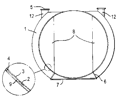
Referring to Figures 1 and 2, these illustrate a storage tank assembly
comprising a storage tank made up of an inner or primary wall 3 and an outer
or
secondary wall 4. These walls are also referred to as skins. The inner and
outer
walls are spaced apart from each other to create an interstitial space 9. The
inner
and outer tanks are sealed at the ends by convex-shaped ends 10, 11 and each
end
also consists of a double skin. Thus, the interstitial space is continuous
around
substantially the whole surface of the outer tank.
Thus far, such tanks are known in the prior art and are conventionally used
in petrol filling stations and the like for storing fuel to be dispensed.
However, the
storage tank assembly illustrated also incorporates reinforcement means 1
formed
from crescent-shaped box sections, or other structural steel sections such as
RSJ,
UB, UC or RSC sections, extending around the sides of the tank. These
structural
supports may be welded directly to the outside of the inner wall 3 and each
box
section extends around approximately one-third of the circumference of the
storage
tank. With one such structural support on either side of tank, approximately
two-
thirds of the tank is encircled in this way. The opposing steel sections are
connected at the base of the storage tank by a saddle support 7 which, as well
as
7
SUBSTITUTE SHEET (RULE 26)
CA 02403351 2002-09-16
WO 01/68510 PCT/GBOI/01159
dispersing the load transmitted through the structural support sections, forms
a rigid,
stable base for the storage tank assembly.
Each set of crescent-shaped sections incorporates a saddle support 7 and
these supports may be linked one to another by longitudinal connections or
fins
which may run substantially the whole length of the storage tank. The saddle
supports are thus formed into a rigid framework and are arranged in
substantially
parallel corresponding end alignment fashion.
In an alternative embodiment, shown in Figure 3, the reinforcement means
21 or structural stiffening extends around substantially around the whole
circumference of the tank. Thus, in comparison with the earlier embodiment,
the
structural supports, in combination with the saddle support, substantially
encircle the
tank. The reinforcement means therefore takes the form of a reinforcement
ring.
This arrangement has the advantage that the baffle plates 8 become redundant
and
can be reduced in size or eliminated entirely. There are no baffle plates
shown in
Figure 3. A substantially circular-shaped reinforcement means is inimensely
strong
and is particularly well adapted for transmitting loads around the tank.
In the context of a reinforcement means the term "structural support" has a
broad meaning. It is intended to encompass any shape of reinforcement or
structural stiffening. It includes box sections or other structural sections
made of
metal eg steel or other materials as recommended by the materials specialist.
Where the tank includes secondary containment then it is possible that the
reinforcement means/structural support may form part of the interstitial space
between primary and secondary layers. If this is the case then the structural
section
must be in the form of a fluid-tight compartment or compartments.
Importantly, the structural sections incorporate short, vertically extending
legs 12, 32 terminating in mounting plates 5, 25. These are adapted to enable
a
8
SUBSTITUTE SHEET (RULE 26)
CA 02403351 2002-09-16
NNO 01 /68510 PCT/G BOl /01159
canopy roof and its associated supporting columns, or other structures for
that
matter, to be mounted directly onto the load bearing reinforcement means box
sections. The consequent load is distributed around the tank and ultimately
onto the
base framework 6, 7, 26, 27.
Where the storage tank incorporates a secondary layer, as in the
illustrations, and where the reinforcement means is attached to the inner
skin, it will
be appreciated that this will be interrupted by structural sections 1, 21.
However, by
providing apertures 2 (see Figure 1) through both legs of the box section
fluid can
pass freely around the whole interstitial space formed between primary and
secondary skins. This is an important feature of this embodiment of the
invention
because, in effect, the box sections become part of the secondary containment
system. With the exception of the apertures 2, the box sections must be fluid
tight.
The apertures 2 preferably take the form of slots or elliptical holes. Since
the space
between the two skins is usually limited, the profile of these apertures must
also be
limited so that they do not extend proud of the outer wall of the tank.
The arrangements shown in Figures 3, 4 and 8 provide for a canopy
mounting which is located substantiaily along the mid-line of the tank. In
order to
achieve this, two mounting plates 5, 25 are located on either side of the
tank. These
mounting plates are attached to vertically extending legs 12, 32 attached
directly to
the reinforcement means 1, 21. These mounting plates 5, 25 are spanned by a
goal
post-type support 34 which in turn supports a conventional canopy mounting
bracket
35. In these examples the canopy-mounting bracket is located above and
substantially in line with the centre of the tank. That is to say it is
located at the
opposite end of an imaginary vertical diameter line starting at the lowest
point in the
tank and joining the highest point of the tank. This, however, is only one
possible
arrangement. Two canopy mounting brackets could be provided, mounted directly
9
SUBSTITUTE SHEET (RULE 26)
CA 02403351 2002-09-16
WO 01/68510 PCT/GB01/01159
on the mounting piates 5, 25. Alternatively a single canopy-mounting bracket
couid
be provided mounted off one or other of the mounting plates. In a further
alternative
a single canopy-mounting bracket could be located centrally on the
reinforcement
means.
In a further important feature of the invention, down beam legs 36, 37 are
detachably mounted to a crossbeam 26 which is part of a base framework. The
advantage of this type of construction is that the tank and its associated
reinforcement means can be detached from the base and removed for replacement
or repair as required. This flexibility is not available in known systems. A
preferred
method of installing this new type of tank assembly is described later. This
will
further explain the advantageous nature of this arrangement.
Figure 4 illustrates a rather more detailed cross-sectional view of the
embodiment described above. Figure 4 illustrates a double-skinned tank with a
reinforcement means 211 in the form of a canopy support ring fully encircling
the
tank. Restraining straps 39' secure the canopy support ring 211 to a crossbeam
261
.
This cross beam is set in concrete during installation and the restraining
straps
prevent the tank lifting if the water table rises, or from rotating.
Figures 5 and 6 illustrate a tank assembly in a completed or partially
completed state depending on how many components are to be included in the
assembly. They illustrate a multi-compartment double skinned tank 53 mounted
on
a series of cross beams 56. These cross beams are linked together by
longitudinal
connections 54. At two points along the length of the tank there are
positioned
canopy support rings 51 and 511 which encircte the tank. These rings are also
linked by longitudinal connections 54. The canopy support rings incorporate
vertically extending legs 62, which can be tapered. terminating in mounting
plates
SUBSTITUTE SHEET (RULE 26)
CA 02403351 2002-09-16
WO 01/68510 PCT/GBOI/01159
55. This provides for the type of canopy mounting arrangement shown generally
in
Figurers 3 and 4.
The location of the canopy support rings aiong the length of the tank can be
varied to suit a particular forecourt and canopy layout. Their positioning can
be
varied within quite wide limits along the length of the tank.
Access chambers 60 can be provided, normally one for each tank
compartment. Also provided are lifting chain or lifting cable eyes 65,66 so
that the
whole assembly can be lifted by crane and lowered into an excavation.
Figure 7 together with Figures 14A to D illustrate in more detail the
arrangement associated with each canopy mounting bracket. and how these relate
to the island on which fuel dispensing pumps are located.
Figures 8 and 9 show a slightly different arrangement whereby the
reinforcement means or canopy support ring 71 extends partially, rather than
fully,
around the tank. Other constructional arrangements remain the same as in
Figures
3 to 7. Whilst some of the strength and rigidity inherent in a fully circular
ring are
lost, the weight of the canopy is still distributed around and through the
tank.
There are a number of ways to attach a canopy support ring to a double
skinned tank of the type in question. In the embodiment shown in Figure 1 a n-
shaped section is tack welded around parts of the circumference of the tank.
The
steel sheets making up the secondary skin of the tank are then overlaid on the
outwardly depending limbs of the n beam and welded to these limbs in a fluid-
tight
fashion. In this arrangement the inside of what is essentially a box section
becomes
part of the secondary containment system. It is therefore essential that the
box
section arrangement is completely fluid-tight.
11
SUBSTITUTE SHEET (RULE 26)
CA 02403351 2002-09-16
WO O1/68510 PCT/GBO1/01159
In a further arrangement, a so-called doubling plate is placed around the
circumference of the tank. This plate takes the form of a steel strip whose
width is
greater than the width of the n-shaped section. The doubling plate is then
tack
weided to the inner tank. The section is laid over the doubling plate and
welded to
it. The steel sheets making up the secondary containment system are then
overlaid
on the exposed edges of the doubling plate and welded to it in a fluid-tight
fashion.
In this manner the section does not become an integral part of the secondary
containment system. This arrangement is considerably easier to manufacture.
Turning now to the method of installation. This is shown most clearly in
Figure 10. A straight-sided excavation 70 is formed to the appropriate depth.
A
layer of stabilised sand (cement/sand mix) 77 is set firm in the bottom of the
excavation. This allows the tank to be held level and allows for some
positioning.
Concrete 72 is then poured into the excavation to cover completely all the
crossbeams. At some time prior to lowering the assembly into the excavation,
usually at the works where the tank assembly is made, the cross beams are
drilled
and reinforcing bars fed through adjoining cross beams along substantially the
entire length of the tank. Reinforcing mesh is then attached over the extent
of the
reinforcing bar area. This whole base frame construction then becomes encased
in
the concrete layer 72.
A layer of pea gravel, which is relatively self-compacting, is added. To
prevent voids under the tank bottom all bedding and back-fill material must be
packed under the lower 120 section of the tank bottom. The solid lines in
Figure 10
between regions 73 and 74 approximate to this 120 angle.
Compacted fill 74 is added up to the bottom of the access chamber to fully
stabilise the tank and to allow additional pipework to be fitted at ground
level. When
12
SUBSTITUTE SHEET (RULE 26)
CA 02403351 2002-09-16
\kO 01'68510 PCT/GB01/01159
this pipework and any other work is compiete the remaining volume 75 is back-
filled
to allow fin grade to be constructed..
In the event that a tank has to be removed the various layers of back-fill 75,
74 and 73 are removed. The down beam legs 77, 78 are detached from the
crossbeam 76 and the remainder of the tank assembly can be lifted out of the
excavation for repair or replacement. Alternatively, the down beam legs can
remain
attached to the crossbeam 76 and instead the legs may be detached from the
canopy ring 71. Both arrangements have the same end result, namely that the
tank
and canopy ring can be detached from the base frame which remains in situ.
Figure 13 illustrates a typical goal post-type canopy support 80. Side
elevation 13A shows two uprights 81 and 82 and spanning cross-member 83. Feet
84, 85 on the bottom of the uprights are a mating fit with mounting plates 5,
25
shown in Figures 2, 3 and 4. The cross-member 83 supports a canopy mounting
bracket 86. Details of this canopy mounting are shown in Figure 14.
It will therefore be appreciated that the present invention also relates to a
fuel dispensing station, comprising at least one fuel tank (other tanks may be
necessary), at least one fuel pump for dispensing fuel contained in said tank
and a
pump canopy which are assembled together as an integrated unit. The present
arrangement transmits the forces from the weight of the canopy around the
tank,
and down into the foundation that is poured on site, or which may be cast in
the
factory and transported as a tank complete with concrete pads. This eliminates
the
formerly mentioned problems as follows:-
a) Reduced excavations are required as there is one foundation which is
poured after the tank is lowered and levelled in the excavation. Other
foundations may be required for extended canopy or island(s) and pump(s)
which are not handled within the invention area.
13
SUBSTITUTE SHEET (RULE 26)
CA 02403351 2002-09-16
WO 01/68510 PCT/GB01/01159
b) This arrangement eliminates the necessity for separate holding down straps
and separate installation of same.
c) The tank is now located directly below the pump and so pipe runs are
reduced.
d) As the tank is located below the island(s) the site can be smaller.
e) As the tank is now underground customers can dispense from both sides of
the island.
f) Security is enhanced due to the tank(s) being underground and access
chambers are less accessible to the public.
g) Temperature variations are reduced as tanks are underground.
The invention therefore provides in a first embodiment a storage tank
assembly for a fuel dispensing station, an example of which is shown
schematically
in Figures 1 and 2. This is installed in an excavation, which has been
backfilled to
the correct depth and levelled. The tank comprises:
= a primary skin 3
= a secondary skin 4 if required
= ends to ctose 10, 11 (shown as dished type in Figure 2).
='crescent' structures 1 including canopy supports 5, integral cradle/saddle
support 7 and longitudinal sections 6. The 'crescent' may have semi-
circular holes or slots 2 partially around the sides of the structure, when
secondary skin is required to allow flow, pressure or vacuum flow
through for leak detection to continue monitoring of the primary skin 3.
= an internal baffle/gusset structure for additional stiffening 8 if required.
This assembly is lowered into the excavation, and checked for level and
height, and then the cement foundation is poured to a predetermined depth, and
compacted. This surrounds the base of the tank and the saddle(s) 7 and the
14
SUBSTITUTE SHEET (RULE 26)
CA 02403351 2002-09-16
WO 01/68510 PCT/CBO1/01159
longitudinal fins 6, which secure and stabilise the tank. This is then left to
set, and
then the backfill material is added and compacted around the tank to a height
that
allows piping of the station to take place. The canopy can then be connected
directly onto the mounting plates 5, or through a 'goal post' structure (not
shown),
and then erected. The island(s) and pump(s) frame(s) can be fastened to assist
piping and levelling, and then the piping can be laid. When tested, the
backfill can
be added and the normal forecourt arrangements completed.
The main features of the present invention can be summarised as follows:-
A double or single walled, underground fuel storage tank which possesses
the followino additional features:
1. External circumferential reinforcement/stiffening welded directly to
primary wall of fuel tank.
2. Integral vertical legs at the top of reinforcement/stiffening to be used
for mounting structural support for future erection of forecourt canopy.
3. Integral bottom cradle/saddle supports (integral also with
circumferential reinforcement/stiffening) used to mount tank inside
underground excavation.
4. Bottom cradle/saddle supports may be linked longitudinally (along
tank length) to form, with circumferential reinforcement/stiffening and
integral vertical legs, a load bearing assembly for future erection of
forecourt canopy.
5. The possibility for reinforcement inside tank to cater for any additional
loads or to deflect any additional loads from tank to integral
supporting structure if the loads cannot be catered for in the external
reinforcement.
SUBSTITUTE SHEET (RULE 26)
CA 02403351 2002-09-16
WO 01 /68510 PCT/G BOl /01159
6. The whole assembly, ie tank, reinforcement internally, externally,
vertical legs, cradles/saddles, longitudinal connections at bottom
between circumferential sections, can be referred to as a framed,
supported fuel system, skid mounted unit or similar designation. The
frame/tank assembly will serve the purpose of holding down after
pouring of concrete foundation.
7. The ability of the tank to cater for any imposed loading from ground
bearing to canopy wind/overturning moments via the above system of
reinforcement/stiffening base frame/skid mounting.
It will be appreciated that as well as the storage tank assembly the invention
also encompasses a pre-fabricated, modular fuel dispensing system including
optionaliy a pump island, fuel pumps and canopy roof.
This invention has been described with a tank of substantially circular cross-
section. This is not essential. Any suitable cross-section can be used such as
elliptical or rectangular cross-section. The reinforcement means or canopy
support
ring will simply follow the external profile of the tank. It follows therefore
that the
term "ring" in this context is not limited to a substantially circular
annulus.
Alternative geometric cross-sections are included within the definition.
Furthermore,
the so-called "canopy support ring" need not fully encircle the tank.
It is also not necessary, although it is desirable, for the reinforcement ring
to
be attached directly to the tank. It can be attached to a doubler plate or it
can be
connected by some other means. For the purposes of this disclosure this range
of
possibilities may be encompassed in the term "directly associated" with the
tank.
16
SUBSTITUTE SHEET (RULE 26)