Language selection

Search

Patent 2403366 Summary

Third-party information liability

Some of the information on this Web page has been provided by external sources. The Government of Canada is not responsible for the accuracy, reliability or currency of the information supplied by external sources. Users wishing to rely upon this information should consult directly with the source of the information. Content provided by external sources is not subject to official languages, privacy and accessibility requirements.

Claims and Abstract availability

Any discrepancies in the text and image of the Claims and Abstract are due to differing posting times. Text of the Claims and Abstract are posted:

  • At the time the application is open to public inspection;
  • At the time of issue of the patent (grant).
(12) Patent Application: (11) CA 2403366
(54) English Title: METALLURGICAL THERMOCOUPLE
(54) French Title: THERMOCOUPLE METALLURGIQUE
Status: Deemed Abandoned and Beyond the Period of Reinstatement - Pending Response to Notice of Disregarded Communication
Bibliographic Data
(51) International Patent Classification (IPC):
(72) Inventors :
  • GRAY, ADRIAN LIONEL (South Africa)
(73) Owners :
  • TEMPERATURE MANAGEMENT SYSTEMS (PROPRIETARY) LIMITED
(71) Applicants :
  • TEMPERATURE MANAGEMENT SYSTEMS (PROPRIETARY) LIMITED (South Africa)
(74) Agent: GOWLING WLG (CANADA) LLP
(74) Associate agent:
(45) Issued:
(86) PCT Filing Date: 2000-08-16
(87) Open to Public Inspection: 2001-02-22
Examination requested: 2003-12-18
Availability of licence: N/A
Dedicated to the Public: N/A
(25) Language of filing: English

Patent Cooperation Treaty (PCT): Yes
(86) PCT Filing Number: PCT/ZA2000/000136
(87) International Publication Number: ZA2000000136
(85) National Entry: 2002-02-08

(30) Application Priority Data:
Application No. Country/Territory Date
99/5203 (South Africa) 1999-08-16

Abstracts

English Abstract


This invention concerns a thermocouple which is protected by an outer sheath
consisting of inner and outer tubes with the annular space filled with low
temperature sintering refractory material which is preferably beaded before
filling in the space and in which the outer tube is constricted to compact the
material. The refractory material will include borosilicate and boric acid
powder.


French Abstract

L'invention concerne un thermocouple protégé par une gaine protectrice, constituée des tubes intérieur et extérieur formant un espace annulaire rempli d'un matériau réfractaire fritté à basse température, de préférence sous forme des billes, avant de remplir l'espace, ledit tube extérieur étant étranglé afin de comprimer le matériau. Ce matériau réfractaire comprend du borosilicate et de la poudre d'acide borique.

Claims

Note: Claims are shown in the official language in which they were submitted.

-7-
CLAIMS
1. A thermocouple comprising a sensing tip in electrical connection with a
mineral insulated thermocouple cable characterised in that additional
external shielding is provided by a low temperature sintering refractory
material including particulate borosilicate and boric acid powder.
2. A thermocouple as claimed in claim 1 characterised in that the shielding is
in the form of a sheath having inner and outer metal tubes constricted over
a filler of low temperature sintering refractory material.
3. A thermocouple as claimed in claim 2 in which the outer tube is
mechanically constricted to compact the filler.
4. A thermocouple as claimed in claim 3 in which the constriction is effected
by
drawing, swaging or rolling.
5. A thermocouple as claimed in claim 1 in which the borosilicate comprises
between 6% and 90% by weight of the refractory material.
6. A thermocouple as claimed in claim 5 in which the boric acid comprises
about 3% to 5% by weight of the refractory material.
7. A thermocouple as claimed in claim 5 or 6 in which the boric acid content
of
the refractory material is about one half of the borosilicate content.
8. A thermocouple as claimed in any one of claims 2 to 7 in which the tubes of
the sheath are stainless steel.
9. A thermocouple as claimed in any one of claims 2 to 8 in which the
refractory material is predried at a temperature of between 135° and
150 °C.
10. A thermocouple as claimed in claim 9 in which the refractory material is
at
least partially sintered before the thermocouple is used.

-8-
11. A thermocouple as claimed in any one of claims 2 to 10 in which the
refractory material is beaded before being formed into the sheath.
12. A thermocouple as claimed in any one of the preceding claims in which the
tip is formed from a thermocouple cable with a negative metal tube housing
a positive wire embedded in a low temperature sintering material as defined
in any one of claims 4 to 7 above.
13. A thermocouple as claimed in any of the preceding claims 1 to 11 in which
the tip is formed by providing a hot junction from the wires of the
thermocouple cable and supported by a sheath as above defined with both
tubes and the refractory formed to cap the hot junction.
14. A thermocouple as claimed in any one of claims 2 to 13 in which the outer
tube of the sheath is annealed after the constriction process and the
refractory material at least partially sintered during the annealing process.
15. A method of shielding a thermocouple comprising locating beads of suitably
bound refractory material between an inner metal tube and an outer metal
tube and reducing the sheath down to a predetermined size by drawing
swaging or rolling during which process the beaded refractory material is
compacted between the inner tube and the outer tube.
16. A thermocouple substantially as described and illustrated in Fig 1 or Fig
2 of
the accompanying drawings.

Description

Note: Descriptions are shown in the official language in which they were submitted.


CA 02403366 2002-02-08
WO 01/13438 PCT/ZA00/00136
-1-
METALLURGICAL THERMOCOUPLE
FIELD OF THE INVENTION
This invention relates to thermocouples and more particularly to thermocouples
for use in determining the temperature of molten metals.
BACKGROUND TO THE INVENTION
Many kinds of thermocouples have been designed and used for use in the
metallurgical industry. In general in the melting and casting processes for
the
production of primary and secondary aluminium the use of so called "Marshall
Tip Thermocouple" has become fairly standard practice. In the baking process
of carbon anodes for the production of aluminium the use of wire and bead or
mineral insulated thermocouples protected by suitable metallic sheaths has
become the norm.
In the ferrous metal industry platinum rhodium type thermocouples are used
because the temperatures of molten steel are generally greater than those at
which some of the components of the thermocouple used in the non-ferrous
industry melt. It is difficult to provide insulation of the platinum rhodium
element
at molten steel temperatures for any length of time and insulation which will
enable repeated use of the thermocouple is also difficult to provide.
Consequently in the interests of economy, the thermocouple for this industry
has
been designed to protect the thermoelement for a maximum of about 4 seconds
of immersion time, which is sufficient to obtain a single measurement.

CA 02403366 2002-02-08
WO 01/13438 PCT/ZA00/00136
-2
Such thermocouples incorporate the smallest amount of the required materials,
and where practical, the lowest cost materials in order to render the device
expendable after only a single immersion into molten iron or steel.
Thus with an overriding cost consideration different thermocouples have been
s developed to meet the particular requirements of particular applications.
There remains however the basic requirements for all thermocouples which is
the
integrity of the temperature measurement obtained. To achieve this it is
necessary that the measuring probe be protected against electrical
conductivity
of its immediate protection material and further that a barrier of sufficient
mechanical strength be provided against the inherently corrosive attack from
the
in situ environment in which the thermocouple is to be used.
OBJECT OF THE INVENTION
As stated the kind of thermocouple used in any application is driven by cost
effectiveness. All of the thermocouples referred to suffer some or other
disadvantage as a result of cost and it is the object of the present invention
to
15 provide a thermocouple which with minor modification can be used in the
ferrous
and non-ferrous industries and which can be made at a high cost effectiveness.
SUMMARY OF THE INVENTION
According to this invention there is provided a thermocouple comprising a
sensing tip and electrical connection with a mineral insulated thermocouple
cable
characterised in that the shielding is provided by a low temperature sintering
2o refractory material.
Further features of this invention provide for the thermocouple cable to be
types
K and N for non-ferrous metals or type W, W3, W5 and molybdenum rhenium for
ferrous metals.
Still further features of this invention provide for the shielding to be in
the form of
a sheath having inner and outer metal tubes over a filler of low temperature
sintering refractory material and for the tubes to be drawn down, swaged or
rolled to compact the filler between them and for a conventional binder
material

CA 02403366 2002-02-08
WO 01/13438 PCT/ZA00/00136
-3
to be added to the refractory material to give it the required green strength
when
the refractory material is beaded before introduction between the tubes.
The invention also provides for the refractory material to include parxiculate
borosilicate and boric acid powder, for the borosilicate to comprise between
6%
by weight of the total refractory material, for the boric acid to comprise
about 3%
to 5% by weight of the total refractory material and for the boric acid
content of
the refractory material to be about one half that of the borosilicate content.
Still further features of this invention provide for the inner and outer tubes
of the
sheath to be of stainless steel.
The invention provides a method of shielding a thermocouple comprising
locating
beads of suitably bound refractory material between an inner metal tube and an
outer metal tube and reducing the sheath down to a predetermined size by
drawing swaging or rolling during which process the beaded refractory material
is
compacted between the inner tube and the outer tube.
15 A further feature of this method provides for the reduced sheath to be
subsequently annealed and the refractory material to be at least partially
sintered
simultaneously with the annealing of the sheath.
Yet further features of this invention provide for the tip to be provided by
the
dissimilar metal wires of the mineral insulated thermocouple cables providing
a
2o hot junction for the thermocouple with the wires embedded in magnesium
oxide
and this latter supported by a sheath as above defined or by a tube of the
same
metal as one wire of the cable housing the other wire of the cable to form the
thermocouple tip with the wire embedded in a low sintering refractory
material.
It is to be understood that where reference is made to metal tubes or wires of
2s thermocouple cable materials being negative and positive Type K or Type W
metals this polarity may be reversed. Further the terms "shield" and
"shielding"
are used to signify both thermal and electrical insulation.
BRIEF DESCRIPTION OF THE DRAWINGS
A preferred embodiment of this invention is described below with reference to
the
accompanying drawing in which

CA 02403366 2002-02-08
WO 01/13438 PCT/ZA00/00136
-4
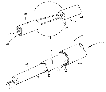
FIG 1 is an oblique view of one form of thermocouple; and
FIG 2 is a section through the tip of an alternative form of thermocouple.
DETAILED DESCRIPTION WITH REFERENCE TO THE DRAWINGS
As illustrated the thermocouple (1 ) is made from a length of conventional
mineral
insulated thermocouple cable (2). This comprises an outer casing (3) of
stainless steel around a magnesium oxide insulating body (4). The thermocouple
is a Type K thermocouple connected to an operating tip (5) having the negative
wire welded to a negative Type K tube (6) which extends around the extended
Type K positive wire (7). A low temperature sintering refractory material (8)
is
packed in the tube (6) around the wire (7).
o As mentioned above the Type K tube may form the positive connection and the
wire the negative connection for the thermocouple tip.
The connection between the mineral insulated thermocouple cable (2) and the
thermocouple tip (5) is located within a suitable metallic oversleeve (8)
having
further low sintering refractory insulation (9) around the cable (2) and tip
(5) and
within the oversleeve (8).
To provide sufficient physical strength as well as further insulation a sheath
(10)
having inner and outer tubes (11 ) and (12) is provided. The annular space
between tubes (11 ) and (12) is first packed with beaded low temperature
sintering refractory (13). The outer tube is then drawn down over the
refractory
2o material crushing the beads to reduce the porosity and also increasing the
physical green strength of the sheath.
The outer tube may be annealed after the drawing operation and the refractory
material at least partially sintered during this annealing process. It has
been
found advantageous to pre-dry the refractory material before use to a
temperature of between 135°and 150°C.
This material may be sintered during in situ use but is preferably at least
partially
presintered by heating before use and maintained under conditions mitigating
the
ingress of moisture.

CA 02403366 2002-02-08
WO 01/13438 PCT/ZA00/00136
-5
It has been found that a very suitable refractory material can be obtained by
the
addition of crushed borosilicate and boric acid powder in a proportion by
weight
of about 2 to 1 to any refractory material. Preferably the borosilicate will
comprise between 6% and 10% of the weight of the composite refractory
material, most preferably about 8%. The applicant has found that this mixture
precipitates a reaction at only ~ 780° C which is very similar to that
of
conventional sintering in which the surface of the aggregate particles soften
and
the particles fuse together to form a more dense mass. It is assumed that the
borosilicate, which has a melting point of about 780° C, provides the
soft surface
0 on each particle, but only in the presence of boric acid. Once formed, it no
longer melts at the same temperature. The result is a dense body that does not
lose its bond even at temperatures in excess of 1000 °C.
Once sintered, the ingress of atmospheric moisture, which must occur because
it
is still porous, appears to have no effect on the electrical conductivity of
such a
body. This is a decided advantage in the manufacture of thermocouples where
the electrical insulation of conductors at elevated temperatures has always
represented a significant problem.
This thermocouple responds instantly when immersed into molten metal, or any
electrically conductive compound which bridges the two conductor ends. This
2o provides temperature measurement of liquids as well as for solids to be
obtained
with the same thermocouple.
It will be appreciated that the thermocouple can be made in an acceptably cost
effective manner.
The thermocouple above described is that which will be used for non-ferrous
metals. For ferrous metals the Type W or molybdenum rhenium thermocouple
cable and tip will be used.
Fig 2 illustrates an alternative form of thermocouple.
In this form the hot junction (15) is formed by baring the ends of the wires
(16)
(17) of the thermocouple and fitting a cap (18) over this junction. The end of
3o the cable is inserted through the sheath (19) which has its end shaped to
close
together to form an outer cap (20) from the outer tube, a continuous layer of
low
temperature sintering refractory material and the closed inner tube.

CA 02403366 2002-02-08
WO 01/13438 PCT/ZA00/00136
-6
This thermocouple may be satisfactorily used where instantaneous temperatures
are not necessary and they can be used to obtain continuous temperature
measurements. Even should the outer tube become eroded shielding is still
afforded by the sintered refractory material.
Thermocouples for both ferrous and non-ferrous material can thus be provided
with a high degree of shielding for both instantaneous and continuous
temperature recordings.

Representative Drawing
A single figure which represents the drawing illustrating the invention.
Administrative Status

2024-08-01:As part of the Next Generation Patents (NGP) transition, the Canadian Patents Database (CPD) now contains a more detailed Event History, which replicates the Event Log of our new back-office solution.

Please note that "Inactive:" events refers to events no longer in use in our new back-office solution.

For a clearer understanding of the status of the application/patent presented on this page, the site Disclaimer , as well as the definitions for Patent , Event History , Maintenance Fee  and Payment History  should be consulted.

Event History

Description Date
Inactive: IPC expired 2023-01-01
Application Not Reinstated by Deadline 2007-08-16
Time Limit for Reversal Expired 2007-08-16
Deemed Abandoned - Failure to Respond to Maintenance Fee Notice 2006-08-16
Amendment Received - Voluntary Amendment 2004-04-01
Letter Sent 2004-01-07
All Requirements for Examination Determined Compliant 2003-12-18
Request for Examination Received 2003-12-18
Request for Examination Requirements Determined Compliant 2003-12-18
Letter Sent 2002-12-02
Inactive: Cover page published 2002-11-21
Inactive: Notice - National entry - No RFE 2002-11-15
Application Received - PCT 2002-10-25
Inactive: Single transfer 2002-04-15
National Entry Requirements Determined Compliant 2002-02-08
Application Published (Open to Public Inspection) 2001-02-22

Abandonment History

Abandonment Date Reason Reinstatement Date
2006-08-16

Maintenance Fee

The last payment was received on 2005-07-19

Note : If the full payment has not been received on or before the date indicated, a further fee may be required which may be one of the following

  • the reinstatement fee;
  • the late payment fee; or
  • additional fee to reverse deemed expiry.

Patent fees are adjusted on the 1st of January every year. The amounts above are the current amounts if received by December 31 of the current year.
Please refer to the CIPO Patent Fees web page to see all current fee amounts.

Fee History

Fee Type Anniversary Year Due Date Paid Date
Basic national fee - standard 2002-02-08
MF (application, 2nd anniv.) - standard 02 2002-08-16 2002-02-08
Registration of a document 2002-04-15
MF (application, 3rd anniv.) - standard 03 2003-08-18 2003-06-19
Request for examination - standard 2003-12-18
MF (application, 4th anniv.) - standard 04 2004-08-16 2004-07-21
MF (application, 5th anniv.) - standard 05 2005-08-16 2005-07-19
Owners on Record

Note: Records showing the ownership history in alphabetical order.

Current Owners on Record
TEMPERATURE MANAGEMENT SYSTEMS (PROPRIETARY) LIMITED
Past Owners on Record
ADRIAN LIONEL GRAY
Past Owners that do not appear in the "Owners on Record" listing will appear in other documentation within the application.
Documents

To view selected files, please enter reCAPTCHA code :


To view images, click a link in the Document Description column (Temporarily unavailable). To download the documents, select one or more checkboxes in the first column and then click the "Download Selected in PDF format (Zip Archive)" or the "Download Selected as Single PDF" button.

List of published and non-published patent-specific documents on the CPD .

If you have any difficulty accessing content, you can call the Client Service Centre at 1-866-997-1936 or send them an e-mail at CIPO Client Service Centre.

({010=All Documents, 020=As Filed, 030=As Open to Public Inspection, 040=At Issuance, 050=Examination, 060=Incoming Correspondence, 070=Miscellaneous, 080=Outgoing Correspondence, 090=Payment})


Document
Description 
Date
(yyyy-mm-dd) 
Number of pages   Size of Image (KB) 
Representative drawing 2002-11-18 1 8
Claims 2002-02-07 2 74
Abstract 2002-02-07 2 65
Drawings 2002-02-07 1 18
Description 2002-02-07 6 244
Notice of National Entry 2002-11-14 1 192
Courtesy - Certificate of registration (related document(s)) 2002-12-01 1 106
Acknowledgement of Request for Examination 2004-01-06 1 188
Courtesy - Abandonment Letter (Maintenance Fee) 2006-10-10 1 175
PCT 2002-02-07 15 566