Language selection

Search

Patent 2403564 Summary

Third-party information liability

Some of the information on this Web page has been provided by external sources. The Government of Canada is not responsible for the accuracy, reliability or currency of the information supplied by external sources. Users wishing to rely upon this information should consult directly with the source of the information. Content provided by external sources is not subject to official languages, privacy and accessibility requirements.

Claims and Abstract availability

Any discrepancies in the text and image of the Claims and Abstract are due to differing posting times. Text of the Claims and Abstract are posted:

  • At the time the application is open to public inspection;
  • At the time of issue of the patent (grant).
(12) Patent: (11) CA 2403564
(54) English Title: METHOD AND APPARATUS FOR MANUFACTURING CEMENT CLINKER FROM PARTICULATE CEMENT RAW MATERIAL
(54) French Title: PROCEDE ET APPAREIL DE FABRICATION DE CIMENT NON BROYE A PARTIR DE MATIERES PREMIERES A BASE DE CIMENT PARTICULAIRE
Status: Expired and beyond the Period of Reversal
Bibliographic Data
(51) International Patent Classification (IPC):
  • C04B 07/43 (2006.01)
  • C04B 07/60 (2006.01)
  • F27B 07/20 (2006.01)
  • F27D 13/00 (2006.01)
(72) Inventors :
  • HUNDEBOL, SOREN (Denmark)
(73) Owners :
  • F.L. SMIDTH & CO. A/S
(71) Applicants :
  • F.L. SMIDTH & CO. A/S (Denmark)
(74) Agent: BORDEN LADNER GERVAIS LLP
(74) Associate agent:
(45) Issued: 2010-03-23
(86) PCT Filing Date: 2001-01-19
(87) Open to Public Inspection: 2001-10-04
Examination requested: 2005-08-26
Availability of licence: N/A
Dedicated to the Public: N/A
(25) Language of filing: English

Patent Cooperation Treaty (PCT): Yes
(86) PCT Filing Number: PCT/IB2001/000054
(87) International Publication Number: IB2001000054
(85) National Entry: 2002-09-18

(30) Application Priority Data:
Application No. Country/Territory Date
PA200000531 (Denmark) 2000-03-30

Abstracts

English Abstract


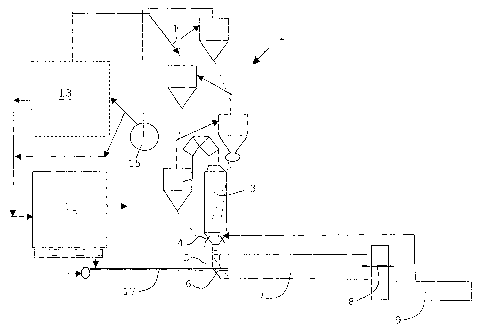
A description is made of a method as well as an apparatus for manufacturing
cement clinker from particulate cement
raw material by which method fresh raw material is preheated and possibly
precalcined in a suspension preheater (1, 3) by heat
exchange with hot exhaust gases, and preheated and possibly precalcined
material is finally calcined and burned into clinker in a
rotary kiln (7), hot clinker from the rotary kiln is cooled in a cooler (9)
and dust is separated from the exhaust gases from the preheater
in a filter arrangement (11). The method and the apparatus are peculiar in
that dust from the filter arrangement (11) is introduced into
the material inlet end of the rotary kiln (7) in a direction which is contrary
to the flow direction of the kiln gases.Hereby is obtained
a significant reduction of coatings on the walls of the riser duct.


French Abstract

L'invention concerne un procédé et un appareil de fabrication de ciment non broyé à partir de matières premières à base de ciment particulaire. Une matière première fraîche est préchauffée et éventuellement précalcinée dans un préchauffeur de suspension (1, 3) par échange thermique avec des gaz d'échappement chauds. Une matière préchauffée et éventuellement précalcinée est finalement calcinée et brûlée dans un four rotatif (7) pour donner du ciment non broyé. Le ciment non broyé chaud sortant du four rotatif est refroidi dans un refroidisseur (9) et la poussière est séparée des gaz d'échappement provenant du préchauffeur dans un arrangement de filtres (11). Le procédé et l'appareil de l'invention sont particuliers en ce que la poussière émanant de l'arrangement de filtres (11) est introduite par l'extrémité d'admission de la matière du four rotatif (7), dans un sens opposé au sens d'écoulement des gaz du four rotatif. On obtient ainsi une réduction considérable des enduits sur les parois de la conduite montante.

Claims

Note: Claims are shown in the official language in which they were submitted.


CLAIMS:
1. A method for manufacturing cement clinker from particulate cement raw
material which method comprises preheating the raw material in a suspension
preheater subject to heat exchange with hot exhaust gases,
calcining and burning the preheated material into clinker in a rotary kiln,
cooling off the clinker in a cooler and separating dust from exhaust gases
from
the preheater in a filter arrangement,
wherein dust from the filter arrangement is introduced into a material inlet
end of the rotary kiln in a direction which is contrary to the flow direction
of the kiln
gases.
2. A method according to claim 1 wherein the raw material is both preheated
and precalcined in the suspension preheater.
3. A method according to claim 1 or 2, wherein the entire filter dust volume
from the filter arrangement is introduced into the material inlet end of the
rotary
kiln in a direction which is contrary to the flow direction of the kiln gases.
4. A method according to claim 1, 2 or 3, wherein the filter dust is injected
into
the rotary kiln by means of pressurized gas.
5. A method according to any one of claims 1 to 4, wherein cold raw material
or
flyash is introduced simultaneously with the filter dust.
6. A plant for carrying out the method according to claim 1 comprising a multi-
stage suspension preheater, a calciner with a plurality of burners, a kiln
riser duct,
a smoke chamber, a rotary kiln with a burner, a clinker cooler and a filter
arrangement, wherein the plant further comprises means for introducing dust
from
the filter arrangement into a material inlet end of the rotary kiln in a
direction
7

which is contrary to the flow direction of the kiln gases.
7. A plant according to claim 6, wherein said means for introducing dust
comprises a lance which is terminated in the smoke chamber of the rotary kiln
or
in the rotary kiln itself, and which extends substantially parallel to the
longitudinal
axis of the rotary kiln.
8

Description

Note: Descriptions are shown in the official language in which they were submitted.


CA 02403564 2003-01-10
METHOD AND APPARATUS FOR,MANUFACTURING CEMENT
CLINKER FROM PARTICULATE CEMENT RAW MATERIAL
The present invention relates to a mettiod for manufacturing cement clinker
from
particulate cement raw material, by which method fresti raw material is
preheated and possibly precalcined in a suspension preheater subject to heat
exchange with hot exhaust gases, preheated and possibly precalcined material
is finally calcined and burned into clinker in a rotary kiln, tiot clinker
from the
rotary kiln is cooled off in a cooler and dust is separated from the exhaust
gases
from the preheater in a filter arrangement. The invention also relates to an
apparatus for carrying out the method according to the invention.
Zo Methods and apparatuses of the aforementioned kind are known.
Essentially all cement raw material mixtures contain at least small quantities
of
Cl, K, Na and S, or such elements are added with the input fuel. In the
burning
zone of the kiln, there will be an evaporation of the various combinations of
such
elements, e.g. KCI, NaCI and KOH, whereas the sulphur will be gaseous in the
form of SOZ. At the cold end of the rotary kiln and in the smoke chamber or
kiln
riser duct there may be a condensation of various salts which will be present
in
the molten state given the prevailing temperatures of 900-1100 C. Formation of
sulphates may also occur. The salts act as a binder for the dust which will
inevitably be present, and massive coatings may be formed, with attendant risk
of blockage in the kiln riser duct. Removement of the coatings may necessitate
suspension of operation, and the lining may be damaged either due to a
reaction
with the coatings or as a result of mechanical damage sustained during the
clean-up operation.
Up to this point in time, it has been common practice to introduce the
preheated
raw material into the kiln riser duct immediately after the discharge of
exhaust
gases from the rotary kiln since this would ensure that the salts are captured
on
the substantial stirface of the raw rnaterial instead of on the walls.
However, it
may be difficult to achieve distribution of the preheated raw rnaterial in the
exhaust gases across the entire cross-sectional area of the kiln riser duct.
The
reason for this is that the raw material is fed, via a downpipe, from the next-
to-
1

CA 02403564 2003-01-10
lowermost cyclone, thus preventing it from attaining the velocity which is
necessary to ensure distribution across the entire cross-sectional area which
may have a width of several metres.
From US patent No. 4.002.420 and US patent No. 4,108.593 methods and
apparatuses are known where hot raw material is extracted from the next-to-
lowermost cyclone stage of the cyclone preheater and is introduced into the
exhaust gases in the material inlet end of the kiln. Hereby is obtained a
lowering
of the temperature of the kiln gases, and thus certain condensation of
lo undesirable vapours, such as alkali, chlorine and sulphur vapours, thereby
reducing ttie problem of coatings in the kiln nser duct. However, the achieved
reduction of coatings has proved to be insufficient. This may be ascribable to
several factors. One explanation could be that the temperature is not reduced
to
sufficient extent and not with the speed required to ensure condensation of
the
1"3 vapours on the raw material particles in the exhaust gases instead of on
the
walls of the riser duct. Another explanation could be that the distribution of
the
raw material does not take place in sufficient degree of homogeneity across
the
cross-sectional area of kiln and/or that the specific surface area of the raw
material is insufficient.
A further general disadvantage of using preheated raw meal is that it will
often
contain salts in condensed form, and, at the prevailir-g temperatures, such
salts
may cause the particles to form lumps, thereby reducing the effective surface
area for capturing the salts contained in the kiln gases.
In the future, coatings in the kiln riser duct are expected to be a major
problem
because of the increase in the thermal loading of the kilns, while, at the
same
time, the kilns are shortened so that they can be supported by two piers
instead
of three.
The present invention seeks to provide a method as well as an apparatus for
manufacturing cement clinker by means of which the
2
..
., , .,.:.. ...:,,,. u...

CA 02403564 2003-01-10
aforementioned problems in terms of coatings in the kiln riser duct are
substantially reduced.
This is achieved by a method of the kind mentioned in the introduction, and
being
distinguished in that dust from the filter arrangement is introduced into the
material inlet end of the rotary kiln in a direction which is contrary to the
flow
direction of the kiln gases. The temperature of the filter dust is typically
less than
300 C and may be appropriately injected with the aid of pressurized gas into
the
material inlet end of the rotary kiln using means comprising a iartice which
terminates in the smoke chamber of the rotary kiln or in the rotary kiln
itself, and
extending substantially parallel to the longitudinal axis of the rotary kiln.
According to the present invention there is provided a method for
manufacturing
cement clinker from particulate cement raw material which method comprises
preheating the raw material in a suspension preheater subject to heat exchange
with hot exhaust gases, calcining and burning the preheated material into
clinker
in a rotary kiln, cooling off the clinker in a cooler and separating dust from
exhaust
gases from the preheater in a filter arrangement, wherein dust from the filter
arrangement is introduced into a material inlet end of the rotary kiln in a
direction
which is contrary to the flow direction of the kiln gases.
Hereby is obtained a significant reduction of coatings on the walls of the
riser
duct. The underlying causes is partly that the temperature of the filter dust
is
lower than that of the preheated raw material, thereby allowing it to absorb a
greater amount of condensation heat, and partly that the filter dust
constitutes the
finest fraction of the raw material, which means that it has a substantial
surface
area, and partly that the filter dust is injected in a direction which is
contrary to the
flow direction of the kiln gases, ensuring even distribution in the kiln gases
across
the entire cross-section of the kiln.
3
_ ... ... . . .......~. ._ -.~,.. ~..,...._ . , .... ...~

CA 02403564 2003-01-10
Up to this point in time, it has been standard practice to blend the filter
dust into
the raw rnaterial mixture prior to its introduction into the preheater. By
extracting
at least some of the filter dust and introducing it into the material inlet
end of the
rotary kiln as proposed according to the present irivention will lead to a
moderate
reduction in the efficiency of the heat exchange process in the preheater.
However, this immediate disadvaritage is compensated by the fact that the raw
material will attain better powder properties in the cyclones when the content
of
filter dust is reduced. As a result, there will be a smaller internal dust
circulation in
the preheater, thus enhancing the efficiency of the preheater, and downtime
due
to cyclone blockages is also expected to decrease. Furthermore, the loading of
the filter in terms of tonnes of dust per hour to be collected by the filter
will be
3a
... r . , M:;: .

CA 02403564 2002-09-18
WO 01/72654 PCT/1B01/00054
reduced, generating savings as far as the dust conveying devices are
concerned.
According to the invention, it amy be preferred to utilize the entire filter
dust
volume and not just a partial volume as a means of combatting coatings by
injecting it into the material inlet end of the rotary kiln. An important spin-
off
benefit is thus achieved. Thus, by injecting the filter dust deep within the
kiln
system it will easier to control the clinker chemistry. Ordinarily, the
composition of
the filter dust exhibits deviations in relation to the rest of the raw
material, and
Zo may, for example, have an excessive lime content, for example up to 200 in
LSF.
If the filter dust is returned to the raw material silo as previously
practised, it will
be necessary to ensure effective blending, with the primary aim being to
maintain
a raw material composition deviating somewhat from that which is necessary for
the clinker. However, if it is preferred to inject the entire filter dust
volume into the
kiln, the composition of raw material needs only to be adjusted to extent
where it
deviates slightly - corresponding to the ash content in the fuels - from the
desired clinker chemistry. In this context, it is a foregone conclusion that
the raw
mill plant comprises means for separating the cement raw materials from the
exhaust gases which are subsequently vented to the filter arrangement for
final
2 o dedusting. Whenever the filter arrangement is also used for separating the
cement raw materials, it is preferred, to maximum practicable extent, that the
finest filter fraction(s) be used for injection into the rotary kiln.
According to the present invention, it will be possible to introduce cold raw
material and/or flyash simultaneously with the filter dust.
The invention will now be explained in further details with reference to the
drawing, being diagrammatical, and its only figure shows a plant according to
the
invention for manufacturing cement.
The figure depicts a plant for manufacturing cement which comprises a multi-
stage suspension preheater 1, a calciner 3, which is fed with fuel via a
number of
4

CA 02403564 2002-09-18
WO 01/72654 PCT/1B01/00054
burners 4 and combustion air via a kiln riser duct 5 and a smoke chamber 6, a
rotary kiln 7, which is fed with fuel via a burner 8, a clinker cooler 9 and a
filter
arrangement 11.
Raw material from an unspecified mill department 13 is introduced into the
preheater 1 at F. From here it is conducted in counter-flow to the hot exhaust
gases from the rotary kiln 7 down through the preheater 1 and the calciner 3.
From the separating cyclone of the calciner 3 the calcined raw material is
directed to the rotary kiln 7 in which it is burned into cement clinker which
is
1o subsequently cooled in the cooler 9. The kiln gases travel in the opposite
direction from the cooler 9 through the rotary kiln 7 in which it is heated
and
continues up through the smoke chamber 6, the kiln riser duct 5, the calciner
4
and the preheater 1, and it is drawn through the kiln system by means of a fan
15. During the preheating process, it is inevitable that a portion,
particularly the
is finest part of the raw materials, is not effectively separated in the
cyclones of the
preheater, instead being entrained in the exhaust gases, and, via the fan 15
and
possibly the mill department, ending up in the filter arrangement 11.
To eliminate the problem mentioned in the introduction in terms of coatings in
the
2 o kiln riser chamber 5, it is proposed according to the invention to
introduce dust
from the filter arrangement 11 into the material inlet end of the rotary kiln
7. The
filter dust may be appropriately injected with the aid of pressurized gas into
the
material inlet end of the rotary kiln 7 by means of a lance 17 which is
terminated
in the smoke chamber 6 of the rotary kiln or in the rotary kiln 7 itself, 'and
25 extending substantially parallel to the longitudinal axis of the rotary
kiln.
So, during the operation of the plant according to the invention dust from the
filter
arrangement 11 is injected into the kiln 7 in counterflow to the kiln gases.
Normally, the dust will be cooled down to a temperature of less than 300 C and
30 often as low as 100 to 150 C in the filter arrangement 11, and,
furthermore, it will
be present in an amount sufficient to ensure proper cooling of the kiln gases
in
the material inlet end of the rotary kiin 7. The injection of the fiiter dust
may be
5

CA 02403564 2002-09-18
WO 01/72654 PCT/1B01/00054
controlled in order to obtain the optimum cooling of the kiln gases depending
on
which salts are present in the gases. The injection of the filter dust entails
that
the temperature of the kiln gases in the material inlet end of the kiln 7 may
be
cooled down from the range 900 to 1200 C to a range about 830 to 850 C, which
s is the decarbonization temperature of the main material component calcium
carbonate, thus resulting in the condensatiori of the salts on the surface of
the
fine filter dust particles.
The invention has been field-tested at an operating cement plant and as a
result
1 o of the test the need to perform clean-out work in the riser duct 5 was
reduced
from once every 8 hours to once a week.
6

Representative Drawing
A single figure which represents the drawing illustrating the invention.
Administrative Status

2024-08-01:As part of the Next Generation Patents (NGP) transition, the Canadian Patents Database (CPD) now contains a more detailed Event History, which replicates the Event Log of our new back-office solution.

Please note that "Inactive:" events refers to events no longer in use in our new back-office solution.

For a clearer understanding of the status of the application/patent presented on this page, the site Disclaimer , as well as the definitions for Patent , Event History , Maintenance Fee  and Payment History  should be consulted.

Event History

Description Date
Time Limit for Reversal Expired 2013-01-21
Letter Sent 2012-01-19
Grant by Issuance 2010-03-23
Inactive: Cover page published 2010-03-22
Pre-grant 2009-11-12
Inactive: Final fee received 2009-11-12
Letter Sent 2009-10-05
Notice of Allowance is Issued 2009-10-05
Inactive: Approved for allowance (AFA) 2009-09-23
Amendment Received - Voluntary Amendment 2009-01-13
Inactive: S.30(2) Rules - Examiner requisition 2008-07-28
Inactive: S.29 Rules - Examiner requisition 2008-07-28
Letter Sent 2005-09-19
Request for Examination Requirements Determined Compliant 2005-08-26
All Requirements for Examination Determined Compliant 2005-08-26
Request for Examination Received 2005-08-26
Inactive: Cover page published 2003-01-16
Letter Sent 2003-01-14
Inactive: Notice - National entry - No RFE 2003-01-14
Amendment Received - Voluntary Amendment 2003-01-10
Application Received - PCT 2002-10-28
National Entry Requirements Determined Compliant 2002-09-18
Application Published (Open to Public Inspection) 2001-10-04

Abandonment History

There is no abandonment history.

Maintenance Fee

The last payment was received on 2009-12-23

Note : If the full payment has not been received on or before the date indicated, a further fee may be required which may be one of the following

  • the reinstatement fee;
  • the late payment fee; or
  • additional fee to reverse deemed expiry.

Patent fees are adjusted on the 1st of January every year. The amounts above are the current amounts if received by December 31 of the current year.
Please refer to the CIPO Patent Fees web page to see all current fee amounts.

Owners on Record

Note: Records showing the ownership history in alphabetical order.

Current Owners on Record
F.L. SMIDTH & CO. A/S
Past Owners on Record
SOREN HUNDEBOL
Past Owners that do not appear in the "Owners on Record" listing will appear in other documentation within the application.
Documents

To view selected files, please enter reCAPTCHA code :


To view images, click a link in the Document Description column. To download the documents, select one or more checkboxes in the first column and then click the "Download Selected in PDF format (Zip Archive)" or the "Download Selected as Single PDF" button.

List of published and non-published patent-specific documents on the CPD .

If you have any difficulty accessing content, you can call the Client Service Centre at 1-866-997-1936 or send them an e-mail at CIPO Client Service Centre.


Document
Description 
Date
(yyyy-mm-dd) 
Number of pages   Size of Image (KB) 
Representative drawing 2002-09-17 1 10
Claims 2002-09-17 2 56
Abstract 2002-09-17 1 60
Drawings 2002-09-17 1 13
Description 2002-09-17 6 305
Description 2003-01-09 7 329
Claims 2003-01-09 2 55
Representative drawing 2010-02-22 1 9
Notice of National Entry 2003-01-13 1 189
Courtesy - Certificate of registration (related document(s)) 2003-01-13 1 107
Acknowledgement of Request for Examination 2005-09-18 1 177
Commissioner's Notice - Application Found Allowable 2009-10-04 1 162
Maintenance Fee Notice 2012-02-29 1 170
PCT 2002-09-17 9 367
Correspondence 2009-11-11 1 33