Language selection

Search

Patent 2404018 Summary

Third-party information liability

Some of the information on this Web page has been provided by external sources. The Government of Canada is not responsible for the accuracy, reliability or currency of the information supplied by external sources. Users wishing to rely upon this information should consult directly with the source of the information. Content provided by external sources is not subject to official languages, privacy and accessibility requirements.

Claims and Abstract availability

Any discrepancies in the text and image of the Claims and Abstract are due to differing posting times. Text of the Claims and Abstract are posted:

  • At the time the application is open to public inspection;
  • At the time of issue of the patent (grant).
(12) Patent Application: (11) CA 2404018
(54) English Title: LIFT AXLE SUSPENSION
(54) French Title: SUSPENSION A ESSIEU RELEVABLE
Status: Withdrawn
Bibliographic Data
(51) International Patent Classification (IPC):
  • B60G 17/04 (2006.01)
  • B60G 5/00 (2006.01)
  • B60G 17/005 (2006.01)
  • B60G 17/052 (2006.01)
(72) Inventors :
  • YAKIMISHYN, KELLY WILLIAM (Canada)
(73) Owners :
  • KELLY WILLIAM YAKIMISHYN
(71) Applicants :
  • KELLY WILLIAM YAKIMISHYN (Canada)
(74) Agent: DOUGLAS B. THOMPSONTHOMPSON, DOUGLAS B.
(74) Associate agent:
(45) Issued:
(22) Filed Date: 2002-09-18
(41) Open to Public Inspection: 2004-03-18
Examination requested: 2006-09-15
Availability of licence: N/A
Dedicated to the Public: N/A
(25) Language of filing: English

Patent Cooperation Treaty (PCT): No

(30) Application Priority Data: None

Abstracts

English Abstract


A lift axle suspension includes an axle and a first
suspension air bag acting one of directly or indirectly in a
downward direction upon the axle. A lever is provided having
a first end, a second end, and a fulcrum selectively
positioned between the first end and the second end. The
first end is linked to the axle. A second lift air bag acts
in a downward direction upon the second end of the lever.
This causes the lever to pivot about the fulcrum such that
the first end of the lever, which is linked to the axle, is
raised. An air diverter selectively supplies air to either
the first suspension air bag to lower the axle or the second
lift air bag to raise the axle.


Claims

Note: Claims are shown in the official language in which they were submitted.

6
THE EMBODIMENTS OF THE INVENTION IN WHICH AN EXCLUSIVE
PROPERTY OR PRIVILEGE IS CLAIMED ARE DEFINED AS FOLLOWS:
1. A lift axle suspension, comprising:
an axle:
a first suspension air bag acting one of directly or
indirectly in a downward direction upon the axle;
a lever having a first end, a second end, and a
selectively positioned fulcrum between the first end and the
second end, the first end being linked to the axle;
a second lift air bag acting in a downward direction
upon the second end of the lever, thereby causing the lever
to pivot about the fulcrum such that the first end of the
lever which is linked to the axle is raised; and
means for selectively supplying air to either the first
suspension air bag to lower the axle or the second lift air
bag to raise the axle.
2. The lift axle suspension as defined in Claim 1, wherein
the first end of the lever is linked to the axle by an
adjustable sling.
3. The lift axle suspension as defined in Claim 1, wherein
the means for selectively supplying air to either the first
suspension air bag to lower the axle or the second lift air
bag to raise the axle is automatic.
4. The lift axle suspension as defined in Claim 3, wherein
the means for selectively supplying air is determined by air
pressure.
5. The lift axle suspension as defined in Claim 1, wherein
the axle is secured to a pivoting arm and the first
suspension air bag acts upon the axle via the pivoting
linkagearm.

7
6. A lift axle suspension, comprising:
a pivoting arm having a pivotal attachment end and a
remote end;
an axle secured to the remote end of the pivoting arm;
a first suspension air bag acting in a downward
direction upon the axle via the pivoting arm;
a lever having a first end, a second end, and a fulcrum
selectively positioned between the first end and the second
end, the first end being linked to the axle by an adjustable
sling;
a second lift air bag acting in a downward direction
upon the second end of the lever, thereby causing the lever
to pivot about the fulcrum such that the first end of the
lever which is linked to the axle is raised;
an air supply tank for supplying air via connection
hoses;
a load leveler valve for maintaining the level of the
vehicle;
an air diverter for selectively diverting air from the
air supply tank to either the first suspension air bag to
lower the axle or the second lift air bag to raise the axle;
and
an air regulator for regulating the pressure of air in
the connection hoses, and the selected one of the first
suspension air bag or the second lift air bag.
7. The lift axle suspension as defined in Claim 6, wherein
the air diverter acts upon air pressure to automatically
selectively divert air to the first suspension air bag or the
second lift air bag.

Description

Note: Descriptions are shown in the official language in which they were submitted.


CA 02404018 2002-09-18
1
TITLE OF THE INVENTION:
Lift Axle Suspension
FIELD OF THE INVENTION
The present invention relates to a lift axle suspension.
BACKGROUND OF THE INVENTION
There are numerous examples of lift axle suspensions in
the patent literature, including: United States Patents
3,201,141 (Bernstein (1965); 4,000,913 (Gibson 1977);
4,256,326 (Cantrell et al 1981); 5,403,031 (Gottschalk et al
1995); 5,549,322 (Hauri 1996); 5,655,788 (Peaker 1997) and
6,416,069 (Ramsey 2002).
The use of a lift axle suspension enables a driver of a
vehicle to lift one or more axles in order to selectively
transfer more weight to the tires that remain on the ground.
This may be done when the vehicle is loaded in order to
increase traction or provide more controlled braking. This
may be done when the vehicle is not loaded in order to save
tire wear.
SLIb~IARY OF THE INVENTION
The present invention is an alternative lift axle
suspension that is believed to provide advantages by virtue
of its relative simplicity.
According to the present invention there is provided a
lift axle suspension that includes a pivoting arm, an axle
and a first suspension air bag acting one of directly or
indirectly in a downward direction upon the axle. A lever is
provided having a first end, a second end, and a fulcrum
positioned between the first end and the second end. The
first end is linked to the axle. A second lift air bag acts
in a downward direction upon the second end of the lever.

CA 02404018 2002-09-18
2
This causes the lever to pivot about the fulcrum such that
the first end of the lever, which is linked to the axle, is
raised. Means is provided for selectively supplying air to
either the first suspension air bag to lower the axle or the
second lift air bag to raise the axle.
The above described lift axle suspension is
characterized by the use of a second air bag to exert a force
upon a lever causing the lever to pivot about its fulcrum and
lift the axle. It provides a distinct advantage over spring
biased systems which have an inherent imbalance in weight
distribution as a result of the action of the biasing spring.
BRIEF DESCRIPTION OF THE DRA~nIINGS
These and other features of the invention will become
more apparent from the following description in which
reference is made to the appended drawings, the drawings are
for the purpose of illustration only and are not intended to
in any way limit the scope of the invention to the particular
embodiment or embodiments shown, wherein:
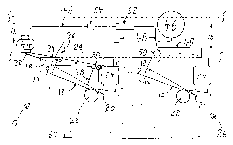
FIGURE 1 is a side elevation view of a lift axle
assembly constructed in accordance with the teachings of the
present invention, with the axle in a lowered position.
FIGURE 2 is a detail, partial side elevation view of the
fulcrum and first end of a lever as illustrated in FIGURE 1.
FIGURE 3 is a side elevation view of the lift axle
assembly illustrated in FIGURE 1. with the axle in a raised
position.
DETAI?~ED DESCRIPTION OF THE PREFRRRED EL~ODII~NT
The preferred embodiment, a lift axle suspension
generally identified by reference numeral 10, will now be

CA 02404018 2002-09-18
3
described with reference to FIGURES 1 through 3.
Structure and Relationship of Parts:
Referring to FIGURE 1, pivot arm 12 having pivotal end
14 that is pivotally attached to vehicle frame 16 by pivot
arm bracket 18. Remote end with adapter 20 is attached to
axle with wheels 22 and is actuated by first suspension air
bag 24 shown in extended mode. All elements 12 through 24
are shown as basic lift axle suspension 26. Preferred
embodiment 10 comprises lever 28 having a first end 30 and
second end 32 which rotates about fulcrum 34 which is
attached to frame 16 by lever bracket 36. An adjustable
sling 38 adapts first end 30 to axle with wheel 22.
Referring to FIGURE 2, lever 28 is further adapted with a
plurality of adjustably positioned fulcrum points 40 and a
sling adjusting mechanism 42. Referring to FIGURE 1, second
end 32 is actuated by second lift air bag 44 shown in
deflation mode. Air supply 46 provides pressure through
connection hoses 48. Pressurized air is channelled through
load leveler valve 50 to air diverter 52 and regulator 54.
Referring to FIGURE 3. axle with wheels 22 is shown in
the elevated position relative to any other axle with wheels
at ground level 56. Second lift air bag 44 is now shown in
extension mode and first suspension air bag 24 is now shown
in deflation mode.
Operation:
The use and operation of a lift axle suspension
generally identified by reference numeral 10, will now be
described with reference to FIGURES 1 through 3. The weight
and contact height of select axles with wheels 22 in
multiple, tandem-axle type vehicles may be changed by
changing the settings of load leveler valve 50, air diverter

CA 02404018 2002-09-18
4
52 and regulator 54. Depending upon the need, air will be
diverted to second lift air bag 44 which in turn actuates
second end 32 of lever 28 causing lever 28 to rotate about
the fulcrum 34 and, in turn, lift first end 30. First end 30
then exerts upward pressure on adjustable sling 38, lifting
axle with wheel 22 which, in turn, lifts remote end with
adapter 20 which is now able to place first suspension air
bag 24 in deflation mode due to the release of pressure
allowed by regulator 54. The result is an elevated wheel
position relative to ground level 56 such that the tires on
axles with wheels 22 that are part of lift axle suspensions
10 are conserved.
Further, should the need to adapt the lift axle
suspension 10 to a different vehicle, an operator may select
one of adjustably positioned fulcrum points 40 and adjust the
sling by operating sling adjustment mechanism 42.
The operation of the above described lift axle
suspension can be manual or automatic. Some jurisdictions do
not allow operators of multiple, tandem-axle type vehicles to
manually operate a lift axle suspension at his or her own
discretion. The reason that laws were passed in such
juridictions is due to abuses in the past, where operators
were exceeding legal load limits. The lift axle suspension,
as illustrated in FIGURES 1 through 3, may be actuated by
means of an automatic system having predetermined settings.
This is accomplished by having the divertor automatically
make a selected diversion in response to air pressure. When
air pressure is below a preset level, the axle is lifted.
When air pressure is above a preset level, the axle is
lowered.
In this patent document, the word "comprising" is used
in its non-limiting sense to mean that items following the
word are included, but items not specifically mentioned are

CA 02404018 2002-09-18
not excluded. A reference to an element by the indefinite
article "a" does not exclude the possibility that more than
one of the element is present, unless the context clearly
requires that there be one and only one of the elements.
5
It will be apparent to one skilled in the art that
modifications may be made to the illustrated embodiment
without departing from the spirit and scope of the invention
as hereinafter defined in the Claims.

Representative Drawing
A single figure which represents the drawing illustrating the invention.
Administrative Status

2024-08-01:As part of the Next Generation Patents (NGP) transition, the Canadian Patents Database (CPD) now contains a more detailed Event History, which replicates the Event Log of our new back-office solution.

Please note that "Inactive:" events refers to events no longer in use in our new back-office solution.

For a clearer understanding of the status of the application/patent presented on this page, the site Disclaimer , as well as the definitions for Patent , Event History , Maintenance Fee  and Payment History  should be consulted.

Event History

Description Date
Inactive: Withdraw application 2010-12-15
Deemed Abandoned - Failure to Respond to Maintenance Fee Notice 2010-09-20
Deemed Abandoned - Conditions for Grant Determined Not Compliant 2010-02-01
Notice of Allowance is Issued 2009-07-30
Letter Sent 2009-07-30
Notice of Allowance is Issued 2009-07-30
Inactive: Approved for allowance (AFA) 2009-07-16
Amendment Received - Voluntary Amendment 2009-02-12
Inactive: S.30(2) Rules - Examiner requisition 2008-08-12
Revocation of Agent Requirements Determined Compliant 2007-09-24
Inactive: Office letter 2007-09-24
Appointment of Agent Requirements Determined Compliant 2007-09-24
Revocation of Agent Request 2007-09-07
Appointment of Agent Request 2007-09-07
Small Entity Declaration Determined Compliant 2007-09-07
Amendment Received - Voluntary Amendment 2006-10-13
Amendment Received - Voluntary Amendment 2006-10-11
Letter Sent 2006-09-20
Request for Examination Received 2006-09-15
Request for Examination Requirements Determined Compliant 2006-09-15
All Requirements for Examination Determined Compliant 2006-09-15
Inactive: IPC from MCD 2006-03-12
Application Published (Open to Public Inspection) 2004-03-18
Inactive: Cover page published 2004-03-18
Inactive: First IPC assigned 2002-11-20
Inactive: Filing certificate - No RFE (English) 2002-10-31
Filing Requirements Determined Compliant 2002-10-31
Application Received - Regular National 2002-10-30

Abandonment History

Abandonment Date Reason Reinstatement Date
2010-09-20
2010-02-01

Maintenance Fee

The last payment was received on 2009-08-21

Note : If the full payment has not been received on or before the date indicated, a further fee may be required which may be one of the following

  • the reinstatement fee;
  • the late payment fee; or
  • additional fee to reverse deemed expiry.

Please refer to the CIPO Patent Fees web page to see all current fee amounts.

Fee History

Fee Type Anniversary Year Due Date Paid Date
Application fee - small 2002-09-18
MF (application, 2nd anniv.) - small 02 2004-09-20 2004-08-20
MF (application, 3rd anniv.) - small 03 2005-09-19 2005-08-19
Request for examination - small 2006-09-15
MF (application, 4th anniv.) - small 04 2006-09-18 2006-09-15
MF (application, 5th anniv.) - small 05 2007-09-18 2007-09-07
MF (application, 6th anniv.) - small 06 2008-09-18 2008-09-05
MF (application, 7th anniv.) - small 07 2009-09-18 2009-08-21
Owners on Record

Note: Records showing the ownership history in alphabetical order.

Current Owners on Record
KELLY WILLIAM YAKIMISHYN
Past Owners on Record
None
Past Owners that do not appear in the "Owners on Record" listing will appear in other documentation within the application.
Documents

To view selected files, please enter reCAPTCHA code :


To view images, click a link in the Document Description column. To download the documents, select one or more checkboxes in the first column and then click the "Download Selected in PDF format (Zip Archive)" or the "Download Selected as Single PDF" button.

List of published and non-published patent-specific documents on the CPD .

If you have any difficulty accessing content, you can call the Client Service Centre at 1-866-997-1936 or send them an e-mail at CIPO Client Service Centre.


Document
Description 
Date
(yyyy-mm-dd) 
Number of pages   Size of Image (KB) 
Representative drawing 2003-01-20 1 12
Description 2002-09-18 5 188
Abstract 2002-09-18 1 19
Claims 2002-09-18 2 74
Drawings 2002-09-18 3 49
Cover Page 2004-02-19 1 39
Description 2006-10-11 5 182
Claims 2006-10-11 3 89
Drawings 2006-10-11 3 45
Description 2006-10-13 5 181
Claims 2006-10-13 3 89
Drawings 2006-10-13 3 45
Claims 2009-02-12 3 91
Filing Certificate (English) 2002-10-31 1 161
Reminder of maintenance fee due 2004-05-19 1 109
Acknowledgement of Request for Examination 2006-09-20 1 176
Commissioner's Notice - Application Found Allowable 2009-07-30 1 161
Courtesy - Abandonment Letter (NOA) 2010-04-26 1 164
Courtesy - Abandonment Letter (Maintenance Fee) 2010-11-15 1 172
Fees 2004-08-20 1 28
Fees 2005-08-19 1 25
Fees 2006-09-15 1 34
Correspondence 2007-09-07 2 60
Fees 2007-09-07 2 74
Correspondence 2007-09-24 1 13
Correspondence 2007-09-24 1 16
Fees 2008-09-05 1 29
Fees 2009-08-21 1 28
Correspondence 2010-12-15 2 44
Correspondence 2010-12-15 1 30
Correspondence 2010-12-29 1 8