Language selection

Search

Patent 2404198 Summary

Third-party information liability

Some of the information on this Web page has been provided by external sources. The Government of Canada is not responsible for the accuracy, reliability or currency of the information supplied by external sources. Users wishing to rely upon this information should consult directly with the source of the information. Content provided by external sources is not subject to official languages, privacy and accessibility requirements.

Claims and Abstract availability

Any discrepancies in the text and image of the Claims and Abstract are due to differing posting times. Text of the Claims and Abstract are posted:

  • At the time the application is open to public inspection;
  • At the time of issue of the patent (grant).
(12) Patent: (11) CA 2404198
(54) English Title: RECREATIONAL VEHICLE FOLDABLE DECK
(54) French Title: PLATE-FORME PLIANTE DE VEHICULE DE PLAISANCE
Status: Expired and beyond the Period of Reversal
Bibliographic Data
(51) International Patent Classification (IPC):
  • B60P 03/37 (2006.01)
  • B60P 03/36 (2006.01)
(72) Inventors :
  • BENZ, DENNIS CLAUDE (Canada)
  • FORTIN, MAURICE ARTHUR (Canada)
  • FORTIN, YVAN AIME (Canada)
(73) Owners :
  • DENNIS CLAUDE BENZ
  • MAURICE ARTHUR FORTIN
  • YVAN AIME FORTIN
(71) Applicants :
  • DENNIS CLAUDE BENZ (Canada)
  • MAURICE ARTHUR FORTIN (Canada)
  • YVAN AIME FORTIN (Canada)
(74) Agent: NATHAN V. WOODRUFFWOODRUFF, NATHAN V.
(74) Associate agent:
(45) Issued: 2011-03-15
(22) Filed Date: 2002-09-20
(41) Open to Public Inspection: 2004-03-20
Examination requested: 2007-09-17
Availability of licence: N/A
Dedicated to the Public: N/A
(25) Language of filing: English

Patent Cooperation Treaty (PCT): No

(30) Application Priority Data: None

Abstracts

English Abstract

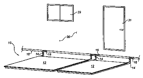
A recreational vehicle foldable deck includes supports adapted for attachment to a structural frame of a recreational vehicle. "L" shaped members are provided. A first end of each of the "L" shaped members is fixedly secured in spaced relation to the platform. A second end of the "L" shaped members is pivotally secured to one of the supports. This enables the platform to be pivotally movable from a substantially vertical stored position parallel to the one side of the recreational vehicle to a substantially horizontal operative position resting at a ground surface.


French Abstract

Un plancher de carrosserie repliable comprend des supports adaptés pour être fixés à un châssis de véhicule de plaisance. Pour se faire, des éléments en L sont fournis. La première extrémité de chacun des éléments en L est fixée à demeure à une certaine distance de la plate-forme. La seconde extrémité des éléments en L est fixée de manière à pivoter par rapport à l'un des supports. Ainsi, la plate-forme peut pivoter, d'une position de rangement quasi verticale par rapport à l'un des côtés du véhicule récréatif, jusqu'à une position d'utilisation quasi horizontale au bas du véhicule.

Claims

Note: Claims are shown in the official language in which they were submitted.


8
THE EMBODIMENTS OF THE INVENTION IN WHICH AN EXLCUSIVE
PROPERTY OR PRIVILEGE IS CLAIMED ARE DEFINED AS FOLLOWS:
1. A recreational vehicle foldable deck, comprising:
at least two supports fixedly attached to a structural frame of a
recreational vehicle;
a platform having a top and an underside;
at least two "L" shaped members, each having a first end and a second
end;
the first end of each of the at least two "L" shaped members being
fixedly secured to the platform in spaced relation; and
the second end of each of the at least two "L" shaped members being
pivotally secured to one of the at least two supports, such that the platform
is
pivotally movable from a substantially vertical stored position parallel to
the
one side of the recreational vehicle to a substantially horizontal operative
position resting at a ground surface.
2. The recreational vehicle foldable deck as defined in Claim 1, wherein one
of
the at least two supports or the at least two "L" shaped members have several
attachment points, thereby permitting adjustment to maintain the platform
close
to the ground surface when in the operative position and close to the one side
of
the recreational vehicle when in the stored position.
3. The recreational vehicle foldable deck as defined in Claim 1, wherein
the platform is a framework covered by a see-through mesh covering, such
that persons are able to see through windows on the recreational vehicle
and air can pass through the platform to utility vents when the platform is in

9
the stored position.
4. The recreation vehicle foldable deck as defined in Claim
1, wherein the platform is segmented into at least two
segments, the segments being independently movable between
the operative position and the stored position, such that
access may be obtained to a door on the recreational vehicle
by lowering only one of the at least two segments to the
operative position.
5. The recreational vehicle foldable deck as defined in Claim
4, wherein there are several segments, the size and weight of
the segments being selected to enable the segments to be
pivoted and manually lifted from the operative position to
the stored position.
6. The recreational vehicle foldable deck as defined in
Claim 4, wherein the segments have tension springs, biasing
the segments into the stored position, thereby reducing the
amount of force required to manually lift the segments from
the operative position to the stored position.
7.The recreational vehicle foldable deck as defined in Claim
1, wherein at least one spring-loaded latch is provided to
latch the platform in the stored position.
8. The recreational vehicle foldable deck as defined in Claim
1, wherein at least one locking pin extends through at least
one of the supports and at least one of the " L" shaped
members to lock the platform in the stored position.

9. A recreational vehicle foldable deck, comprising:
supports adapted for attachment to a structural frame
along one side of a recreational vehicle, each of the
supports having several apertures;
a platform having a top, an underside and segmented into
at least two segments;
" L" shaped members, each having a first end, a second
end and several apertures;
the first end of each of the " L" shaped members being
fixedly secured in spaced relation to one of the segments of
the platform, there being at least two " L" shaped members
for each of the segments; and
the second end of each of the " L" shaped members being
pivotally secured to one of the supports, such that each
segment of the platform is pivotally movable from a
substantially vertical stored position parallel to the one
side of the recreational vehicle to a substantially
horizontal operative position resting at a ground surface,
each of the " L" shaped members being pivotally secured to
the supports by pivot pins extending through a selected one
of the apertures in one of the supports and a selected one of
the apertures in one of the " L" shaped members, the
selection of the respective apertures in the supports and
" L" shaped members thereby permitting adjustment to maintain
the segment of the platform close to the ground surface when
in the operative position and close to the one side of the
recreational vehicle when in the stored position, the
segments being independently movable between the operative
position and the stored position, such that access may be
obtained to a door on the recreational vehicle by lowering
only one of the at least two segments to the operative
position, each segment consisting of a framework covered by a
see-through mesh covering, such that persons are able to see
through windows on the recreational vehicle and air can pass

11
through the segments to utility vents when the segments of
the platform are in the stored position, the size and weight
of the segments being selected to enable the segments to be
pivoted and manually lifted from the operative position to
the stored position, the segments having tension springs
biasing the segments into the stored position, thereby
reducing the amount of force required to manually lift the
segments from the operative position to the stored position;
a spring loaded latch being provided to latch the
platform in a stored position and provision being made to
lock the platform in the stored position by extending locking
pin through one of the apertures in one of the supports and
one of the apertures in one of the " L" shaped members.

Description

Note: Descriptions are shown in the official language in which they were submitted.


CA 02404198 2002-09-20
1
TITLE OF THE INVENTION:
Recreational Vehicle Foldable Deck
FIE7~D OF THE INVENTION
The present invention relates to a deck that is secured
to a recreational vehicle for movement between a
substantially horizontal operative position and a
substantially vertical stored position.
BACKGROUND OF THE INVENTION
United States Patent 5,417,468 (Baumgartner et al)
discloses a recreational vehicle foldable deck. The foldable
deck of Baumgartner et al consists of a rectangular platform
1:o pivotally secured along a bottom edge of the recreational
vehicle. The platform is pivotally movable between a
substantially horizontal operative position and a
substantially vertical stored position. When the platform is
in the operative position, the platform is elevated on a
plane which is approximately even with the height of the
wheel axles. This distance, of roughly 12 inches from the
ground, is accommodated by having support members pivotally
attached along a remote edge of the platform. An elevated
platform of this nature presents a potential hazard as, in
the absence of a guard rail, persons may fall from the
platform.
SUN~1ARY OF THE INVENTION
What is required is a recreational vehicle foldable deck
in which the risk of persons falling from the platform is
reduced.
According to the present invention there is provided a
recreational vehicle foldable deck which includes at least

CA 02404198 2002-09-20
2
two supports adapted for attachment to a structural frame
along one side of a recreational vehicle. A platform is
provided having a top and an underside and is adapted with at
least two " L" shaped members. The " L" shaped members have
a first end and a second end. The first end of each of the
" L" shaped members is fixedly secured in spaced relation to
the platform. The second end of each of the " L" shaped
members is pivotally secured to one of the supports. This
enables the platform to be pivotally movable from a
substantially vertical stored position parallel to the one
side of the recreational vehicle to a substantially
horizontal operative position resting at a ground surface.
With the recreational vehicle foldable deck, as
described above, the platform is always resting on'or
immediately above the ground surface.
Although beneficial resu7_ts may be obtained through the
use of the recreational vehicle foldable deck, as described
above, the height of recreational vehicles varies. Even more
beneficial results may, therefore, be obtained when either
the supports or the " L" shaped members has several
attachment points. By selection of attachment points, an
adjustment may be made to maintain the platform close to the
ground surface when in the operative position and close to
the one side of the recreational vehicle when in the stored
position.
Although beneficial results may be obtained through the
use of the recreational vehicle foldable deck, as described
above, it is preferred that th.e platform be in the form of a
framework covered by a see-through mesh covering. This
enables persons to see through windows on the recreational
vehicle and air can pass through the platform to utility

CA 02404198 2002-09-20
3
vents when the platform in the stored position.
Although beneficial results may be obtained through the
use of the recreation vehicle foldable deck, as described
above, it is preferred that the platform be segmented into
two or more segments each of which is independently movable
between the operative position and the stored position. This
enables access to be obtained to a door on the recreational
vehicle by lowering only one of the segments to the operative
position. It is preferred that the size and weight of the
segments be selected to enable the segments to be pivoted and
manually lifted from the operative position to the stored
position. It is also preferred that the segments have
tension springs biasing the segments into the stored
position. The biasing force of. the springs serves to reduce
the amount of force required t:o manually lift the segments
from the operative position to the stored position.
Although beneficial results may be obtained through the
use of the recreational vehicle foldable deck, as described
above, it is preferred that some means be provided to secure
the platform in the stored po:~ition. In the description that
follows two such means will be described. A spring-loaded
latch is described which serves to latch the platform in the
2~ stored position. In addition, a locking pin may be extended
through the supports and the 'y L" shaped members to lock the
platform in the stored position.
BRIEF DESCRIPTION OF THE DRAWINGS
These and other features of the invention will become
more apparent from the following description in which
reference is made to the appended drawings, the drawings are
for the purpose of illustration only and are not intended to

CA 02404198 2002-09-20
4
in any way limit the scope of the invention to the particular
embodiment or embodiments shown, wherein:
FIGURE 1 is a perspective view of a recreational vehicle
foldable deck with multiple segments shown in an operative
position constructed in accordance with the teachings of the
present invention.
FIGURE 2 is a side elevation view of the recreational
vehicle foldable deck illustrated in FIGURE 1 in an operative
position.
FIGURE 3 is a side elevation view of the recreational
vehicle foldable deck illustrated in FIGURE 1 in a stored
position.
FIGURE 4 is a side elevation view of the recreational
vehicle foldable deck illustrated in FIGURE 1, equipped with
a biasing spring and positioned in an operative position.
FIGURE 5 is a top elevation view of one of the segments
of the recreational vehicle foldable deck illustrated in
FIGURE 1.
FIGURE 6 is a bottom elevation view of one of the
segments of the recreational vehicle foldable deck
illustrated in FIGURE 1.
DETAILED DESCRIPTION OF THE PREFERRED EMBODIMENT
The preferred embodiment, a recreational vehicle
foldable deck generally identified by reference numeral 10,
will now be described with reference to FIGURES 1 through 6.
Structure and Relationship of Parts:
Referring to FIGURE l, foldable deck 10 has a platform
which is segmented into a two or more segments 12. Segmented
platform 12 is attached to " L" shaped members 14 which are
pivotally attached to supports 16. Supports 16 are, in turn,
fixedly attached to frame 18 of one side of recreational

CA 02404198 2002-09-20
vehicle 20. Each one of segmented platforms 12 is pivotally
movable between a substantially horizontal operative position
illustrated in FIGURE 2 and a substantially vertical stored
position illustrated in FIGURE 3. Referring to FIGURE 2~ " L
5 shaped member 14 has a first end 22 and a second end 24.
First end 22 is fixedly attached to segmented platform 12.
Second end 24 is adapted with a plurality of attachment
points 26. Support 16 is similarly adapted with a second
plurality of attachment points 28. Each of " L" shaped
members 14 is pivotally secured to supports 16 by pivot pins
25 extending through a selected one o.f apertures 28 in
supports 16 and a selected one of apertures 26 in " L" shaped
members 14. The selection of the respective apertures 28 and
26 in supports 16 and " L" shaped members, respectively,
permits adjustment to maintain platform segment 12 close to
the ground surface when in the operative position as
illustrated in FIGURE 2 and close to the one side of the
recreational vehicle 20 when in the stored position, as
illustrated in FIGURE 3. Referring to FIGURE 2, second end 24
is shown substantially right angle to support 16 when
segmented platform 12 is in the substantially horizontal
operative position with an underside 30 of segmented platform
12 oriented downwards toward ground surface 32. Referring to
FIGURE 3~ second end 24 is shown substantially parallel with
support 16 when segmented platform 12 is in a substantially
vertical stored position with a top 34 of segmented platform
12 oriented towards one side of recreational vehicle 20. A
spring loaded latch mechanism 38 positioned along a
peripheral edge of segmented platform 12 serves to secure
segmented platform 12 in the substantially vertical stored
position. When recreational vehicle 20 is going to be
travelling on a highway, a locking pin 36 can be inserted
apertures in " L" shaped member 14 and support 16 to further
secure segmented platform 12 .Ln a substantially vertical

CA 02404198 2002-09-20
6
stored position. The apertures which receive locking pin 36
are best illustrated in FIGURE 2. those apertures being
apertures 27 on ~~ L" shaped member 14 and apertures 29 on
supports 16. Referring to FIGURE 4. ~~ L'~ shaped member 14
may optionally be equipped with a tension spring 40, which
acts against support 16. Referring to FIGURE 5. it is
preferred that top 34 of segmented platform 12 be covered
with a metal lattice work of see-through mesh 42. Referring
to FIGURE 6. underside 30 of segmented platform 12 has
framework 44 and spring-loaded latch assembly 38.
Operation:
The use and operation cf recreational vehicle foldable
deck 10 will now be described with reference to FIGURES 1
through 6. Referring to FIGURE 1, recreational vehicle
foldable deck 10 may be lowered to a substantially horizontal
operative position as shown wherein each segment of segmented
platform 12 is oriented substantially below the level of
frame 18. Referring to FIGURES 2 and 3, users, by
selectively adjusting the pivotal attachment via plurality of
attachment points 26 or second plurality of attachment points
28, may orient underside 30 and framework 44 of segmented
deck 12 to a substantially close position relative to ground
surface 32. Further, users. may lift any segment of the
segmented platform 12 and place each segmented platform 12 in
a substantially vertical storage position. Referring to
FIGURE 4. the raising of segmented platform may, optionally,
be assisted by tensioning spring 40. Referring to FIGURE 3~
when in the substantially vertical stored position, foldable
deck 10 is secured in position with spring loaded latch
assembly 38. Prior to highway travel, locking pin 36 may be
placed in position as an addit=ional safety precaution.
It will be apparent to one skilled in the art from a

CA 02404198 2002-09-20
7
review of FIGURE 1. the advantage that the described
segmented platform provides. Having the segments
independently movable between the operative position and the
stored position enables access to be obtained to a door 31 on
recreational vehicle 2G by lowering only one of the platform
segments 12 to the operative position. Having the platform
segmented reduces the size and weight of each of the
individual segments, enabling them be manually pivoted and
lifted from the operative position to the stored position.
By having each segment consisting of a framework covered by a
see-through mesh covering, persons are able to see through
windows 33 on recreational vehicle 20 and air can pass
through each of platform segments 12 to utility vents and the
like when the platform segments 20 are in the stored
position.
In this patent document, the word "comprising" is used
in its non-limiting sense to mean that items following the
word are included, but items not specifically mentioned are
not excluded. A reference t=o an element by the indefinite
article "a" does not exclude the possibility that more than
one of the element is present, unless the context clearly
requires that there be one and only one of the elements.
It will be apparent to one skilled in the art that
modifications may be made to the illustrated embodiment
without departing from the spirit and scope of the invention
as hereinafter defined in the Claims.

Representative Drawing
A single figure which represents the drawing illustrating the invention.
Administrative Status

2024-08-01:As part of the Next Generation Patents (NGP) transition, the Canadian Patents Database (CPD) now contains a more detailed Event History, which replicates the Event Log of our new back-office solution.

Please note that "Inactive:" events refers to events no longer in use in our new back-office solution.

For a clearer understanding of the status of the application/patent presented on this page, the site Disclaimer , as well as the definitions for Patent , Event History , Maintenance Fee  and Payment History  should be consulted.

Event History

Description Date
Time Limit for Reversal Expired 2013-09-20
Letter Sent 2012-09-20
Appointment of Agent Requirements Determined Compliant 2011-04-26
Inactive: Office letter 2011-04-26
Revocation of Agent Requirements Determined Compliant 2011-04-26
Grant by Issuance 2011-03-15
Inactive: Cover page published 2011-03-14
Pre-grant 2010-12-20
Inactive: Final fee received 2010-12-20
Notice of Allowance is Issued 2010-06-23
Letter Sent 2010-06-23
Notice of Allowance is Issued 2010-06-23
Inactive: Approved for allowance (AFA) 2010-06-17
Amendment Received - Voluntary Amendment 2010-02-19
Inactive: S.30(2) Rules - Examiner requisition 2009-09-02
Letter Sent 2007-10-30
Revocation of Agent Requirements Determined Compliant 2007-10-26
Appointment of Agent Requirements Determined Compliant 2007-10-26
Inactive: Office letter 2007-10-26
Small Entity Declaration Determined Compliant 2007-10-17
Revocation of Agent Request 2007-10-17
Appointment of Agent Request 2007-10-17
Inactive: <RFE date> RFE removed 2007-09-25
Inactive: Office letter 2007-09-25
Inactive: Adhoc Request Documented 2007-09-25
Appointment of Agent Request 2007-09-17
Request for Examination Requirements Determined Compliant 2007-09-17
All Requirements for Examination Determined Compliant 2007-09-17
Revocation of Agent Request 2007-09-17
Request for Examination Received 2007-09-17
Inactive: IPC from MCD 2006-03-12
Application Published (Open to Public Inspection) 2004-03-20
Inactive: Cover page published 2004-03-19
Inactive: First IPC assigned 2002-11-21
Inactive: Filing certificate - No RFE (English) 2002-11-01
Application Received - Regular National 2002-10-31
Small Entity Declaration Determined Compliant 2002-09-20

Abandonment History

There is no abandonment history.

Maintenance Fee

The last payment was received on 2010-09-17

Note : If the full payment has not been received on or before the date indicated, a further fee may be required which may be one of the following

  • the reinstatement fee;
  • the late payment fee; or
  • additional fee to reverse deemed expiry.

Patent fees are adjusted on the 1st of January every year. The amounts above are the current amounts if received by December 31 of the current year.
Please refer to the CIPO Patent Fees web page to see all current fee amounts.

Fee History

Fee Type Anniversary Year Due Date Paid Date
Application fee - small 2002-09-20
MF (application, 2nd anniv.) - small 02 2004-09-20 2004-08-20
MF (application, 3rd anniv.) - small 03 2005-09-20 2005-09-09
MF (application, 4th anniv.) - small 04 2006-09-20 2006-09-12
MF (application, 5th anniv.) - small 05 2007-09-20 2007-09-17
Request for examination - small 2007-09-17
MF (application, 6th anniv.) - small 06 2008-09-22 2008-09-02
MF (application, 7th anniv.) - small 07 2009-09-21 2009-09-16
MF (application, 8th anniv.) - small 08 2010-09-20 2010-09-17
Final fee - small 2010-12-20
MF (patent, 9th anniv.) - small 2011-09-20 2011-09-12
Owners on Record

Note: Records showing the ownership history in alphabetical order.

Current Owners on Record
DENNIS CLAUDE BENZ
MAURICE ARTHUR FORTIN
YVAN AIME FORTIN
Past Owners on Record
None
Past Owners that do not appear in the "Owners on Record" listing will appear in other documentation within the application.
Documents

To view selected files, please enter reCAPTCHA code :


To view images, click a link in the Document Description column. To download the documents, select one or more checkboxes in the first column and then click the "Download Selected in PDF format (Zip Archive)" or the "Download Selected as Single PDF" button.

List of published and non-published patent-specific documents on the CPD .

If you have any difficulty accessing content, you can call the Client Service Centre at 1-866-997-1936 or send them an e-mail at CIPO Client Service Centre.


Document
Description 
Date
(yyyy-mm-dd) 
Number of pages   Size of Image (KB) 
Description 2002-09-19 7 311
Abstract 2002-09-19 1 18
Claims 2002-09-19 4 151
Drawings 2002-09-19 5 125
Representative drawing 2004-03-07 1 11
Claims 2010-02-18 4 148
Drawings 2010-02-18 5 122
Representative drawing 2011-02-07 1 12
Filing Certificate (English) 2002-10-31 1 161
Reminder of maintenance fee due 2004-05-24 1 109
Reminder - Request for Examination 2007-05-22 1 118
Acknowledgement of Request for Examination 2007-10-29 1 177
Commissioner's Notice - Application Found Allowable 2010-06-22 1 164
Maintenance Fee Notice 2012-10-31 1 171
Fees 2004-08-19 1 30
Fees 2005-09-08 1 29
Fees 2006-09-11 1 26
Correspondence 2007-09-16 3 70
Fees 2007-09-16 2 72
Correspondence 2007-09-24 1 16
Correspondence 2007-10-16 3 59
Correspondence 2007-10-25 1 15
Correspondence 2007-10-25 1 17
Fees 2008-09-01 1 28
Fees 2009-09-15 1 28
Fees 2010-09-16 1 199
Correspondence 2010-12-19 1 26
Correspondence 2011-03-30 3 158
Correspondence 2011-04-25 1 13
Correspondence 2011-04-25 1 16