Language selection

Search

Patent 2404215 Summary

Third-party information liability

Some of the information on this Web page has been provided by external sources. The Government of Canada is not responsible for the accuracy, reliability or currency of the information supplied by external sources. Users wishing to rely upon this information should consult directly with the source of the information. Content provided by external sources is not subject to official languages, privacy and accessibility requirements.

Claims and Abstract availability

Any discrepancies in the text and image of the Claims and Abstract are due to differing posting times. Text of the Claims and Abstract are posted:

  • At the time the application is open to public inspection;
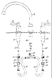
  • At the time of issue of the patent (grant).
(12) Patent: (11) CA 2404215
(54) English Title: QUICK CONNECT/DISCONNECT WATER FAUCET CONDUIT ASSEMBLY
(54) French Title: TUBES A RACCORDS RAPIDES POUR ROBINET A EAU
Status: Deemed expired
Bibliographic Data
(51) International Patent Classification (IPC):
  • F16K 27/00 (2006.01)
  • E03C 1/04 (2006.01)
(72) Inventors :
  • BURNS, LEONARD J. (United States of America)
  • MASCARI, NICHOLAS A. (United States of America)
  • ZUMMERSCH, MARTIN (United States of America)
(73) Owners :
  • MOEN INCORPORATED (United States of America)
(71) Applicants :
  • MOEN INCORPORATED (United States of America)
(74) Agent: NORTON ROSE FULBRIGHT CANADA LLP/S.E.N.C.R.L., S.R.L.
(74) Associate agent:
(45) Issued: 2011-02-01
(22) Filed Date: 2002-09-20
(41) Open to Public Inspection: 2003-03-28
Examination requested: 2007-09-14
Availability of licence: N/A
(25) Language of filing: English

Patent Cooperation Treaty (PCT): No

(30) Application Priority Data:
Application No. Country/Territory Date
09/967,020 United States of America 2001-09-28

Abstracts

English Abstract

A quick connect/disconnect faucet water conduit assembly includes at least one valve body and a spout nipple. There is a water tube extending from the valve body and a water tube extending from the spout nipple. A conduit has first and second terminations and there is a quick connect adapter attached to each of the first and second terminations. There are cooperating elements on each of the tubes and the quick connect adapters for locking the tubes to the adapters to thereby attach the valve body to the spout nipple.


French Abstract

Un ensemble de tubes à raccords rapides pour robinet d'eau comprend au moins un corps de robinet et un raccord de bec. Un tube est muni d'une première et d'une deuxième extrémités et un raccord rapide est fixé à chacune des première et deuxième extrémités. Des éléments coopérant sont montés sur chacun des tubes et des raccords rapides pour verrouiller les tubes sur les raccords et pour ainsi fixer le corps du robinet au raccord du bec.

Claims

Note: Claims are shown in the official language in which they were submitted.


CLAIMS

The embodiments of the invention in which an exclusive property or privilege
is
claimed are as follows:

1. A quick connect/disconnect faucet water conduit assembly including at least
one
valve body and a spout nipple, a water tube extending from said valve body and
a water tube
extending from said spout nipple,

a conduit having first and second terminations, a quick connect adapter
attached to each
of said first and second terminations, and cooperating means on each of said
tubes and each of
said quick connect adapters for removably locking each tube to an adapter to
thereby attach
said conduit between said spout nipple and said valve body.

2. The faucet water conduit assembly of claim 1 wherein said cooperating means
includes an interlocking element on each tube, and a movable clip located in
each quick
connect adapter.

3. The faucet water conduit assembly of claim 2 wherein the interlocking
element on
each tube includes a shoulder formed thereon.


6


4. The faucet water conduit assembly of claim 2 wherein each clip is
positioned within
and movable within a chamber in each quick connect adapter.

5. The faucet water conduit assembly of claim 4 wherein each clip includes a
pair of
flexible arms permitting said clip to move inwardly and outwardly of said
chamber.

6. The faucet water conduit assembly of claim 5 wherein the arms and each clip
are
joined by an arcuate portion of said clip, with said clip having an interior
locking portion
formed and positioned to interlock with a shoulder on a tube.

7. The faucet water conduit assembly of claim 3 wherein each quick connect
adapter
has an annular recess, spaced from its chamber, with said shoulder being
positioned in said
recess to hold said tube within said quick connect adapter.

8. The faucet water conduit assembly of claim 1 further including a second
valve body
having a water tube extending therefrom, a second conduit having first and
second
terminations, a quick connect adapter attached to a first termination of said
second conduit and
cooperating means on the tube of said second valve body and the quick connect
adapter on the
first termination of said second conduit for removably locking the tube of
said second valve
body to the quick connect adapter at the first termination of said second
conduit.


7


9. The faucet water conduit assembly of claim 8 including a fixture supporting
the
quick connect adapter for said spout nipple, said fixture having means thereon
for mounting
terminations of said first and second conduits to connect both valve bodies to
said spout nipple.

10. The faucet water conduit assembly of claim 9 wherein said fixture includes
a body
having first and second inlets and an outlet, with the inlets being attached
to said first and
second conduits and the outlet supporting the quick connect adapter for said
spout nipple.

11. The faucet water conduit assembly of claim 10 wherein each of said
conduits
includes a hose having a flexible end thereon, the inlets of said fixture
valve body each having
a projection which extends into the flexible ends of said hoses, with the
inlets including means
for attaching the fixture body to the flexible end of the hoses.


8

Description

Note: Descriptions are shown in the official language in which they were submitted.


CA 02404215 2002-09-20
1018-0737.01
QUICK CONNECT/DISCONNECT WATER
FAUCET CONDUIT ASSEMBLY
The Field of the Invention
[0001] The present invention relates to a quick connect/disconnect faucet
water conduit
assembly which facilitates the connection between a spout nipple and the valve
bodies which
control the flow of water to the spout nipple. Present practice in the
installation of faucets,
particularly kitchen faucets, which require a below deck water connection
between the valve
bodies and the spout nipple, necessitates a mechanical connection at each end
of a water
conduit. These may be soldered connections, or they may use a nut and a
threaded end on the
valve body. Either type of connection is time consuming and requires the
installer to spend a
considerable period beneath the sink deck.
[0002] The present invention provides a hose assembly which has a quick
connect/disconnect adapter at each end thereof. The adapters are seal.ingly
attached to the
hose, which may be flexible, and cooperate and interlock with a tube which
extends down from
the valve body and the spout nipple. The installer need only snap the quick
connect adapter
onto the end of the water tube from the valve body and the water tube from
spout nipple and
the installation is complete. The hose may be disconnected by manipulating the
clip on the
adapter if there is a necessity to change out the valve body or the spout
nipple.

CA 02404215 2002-09-20
Summary of the Invention
[0003] The present invention relates to a faucet water conduit assembly which
may be
quickly connected and disconnected to a valve body and a spout nipple.
[0004] A primary purpose of the invention is to provide a water conduit
assembly which
utilizes quick connect adapters to form a watertight connection between one or
more valve
bodies and a spout nipple.
[0005] Another purpose of the invention is to provide a water conduit assembly
for the use
described utilizing quick connect adapters which cooperate and interlock with
a tube which
extends outwardly from a faucet spout nipple and a faucet valve body.
[0006] Other purposes will appear in the ensuing specification, drawings and
claims.
Brief Description of the Drawings
[0007] The invention is illustrated diagrammatically in the following drawings
wherein:
[0008] Fig. 1 is a diagrammatic illustration of a kitchen faucet assembly and
the water
conduit connections therebetween;
[0009] Fig. 2 is an exploded view of the hose connection between any one of
the faucet
fixtures shown in Fig. 1;
[0010] Fig. 3 is a top plan view of the quick connect adapter; and
[0011] Fig. 4 is an enlarged view illustrating the connection between the
adapter and the
water tube from a valve body or spout nipple.
Description of the Preferred Embodiment
[0012] Fig. 1 illustrates a typical kitchen faucet installation. There are
control handles 10
and 12 on each side of a faucet spout 14. Each of the handles 10 and 12 has a
valve body
2

CA 02404215 2002-09-20
indicated at 16 and 18, respectively, and the spout 14 has a spout nipple 20.
Suitable valve
cartridges, such as the MOEN 1224, may be positioned within the valve bodies.
As is well
known in the art, the handles control the flow of water from hot and cold
water supplies to the
spout nipple from which the water is discharged through the spout. The present
invention is
specifically concerned with the water connections between the valve bodies and
the spout
nipple.
[0013] Each of the valve bodies 16 and 18 has an inlet water conduit 22 and 24
extending
downwardly therefrom, with each terminating in a connector 26 and 28,
respectively. The
valve bodies in turn each have a water outlet tube 30 and 32 at the end
thereof. Similarly, the
spout nipple body 20 has a tube 34 extending downwardly therefrom. The tubes
30, 32 and 34
and their connection to the hose assembly is illustrated in more detail in
Figs. 2-4.
[0014] Also illustrated in Fig. 1 are a pair of water conduits or hoses 36 and
38. The hose
38 is connected between a spout nipple fitting 40 arid a valve body fitting 42
and the hose 36 is
connected between the spout nipple fitting 40 and the valve body fitting 44.
Figs. 2-4
represent and illustrate the connection between a water tube, whether it be
any one of tubes 30,
32 and 34, and the valve body fittings 40, 42 and 44.
[0015 Focusing first on the connection between the hose and the valve body
fitting,
indicated at 42 in Fig. 2, the fitting may be made of a suitable plastic and
has a cylindrical
portion 46 having an outwardly extending barbed projection 48. The barbed
projection 48
extends within a flexible portion 50 of the hose 36. There is a seal ring 52
on the barbed
projection, and as shown, this will cause an expansion area 54 in the flexible
hose portion 50.
This provides a seal between the fitting and the hose. The barbs 56 function
to secure the
3

CA 02404215 2002-09-20
fitting to the hose. The combination of the barbed projection and seal
provides a sealed
secured connection between the hose and the fitting.
[0016] The tube 30 carries a shoulder 58 which will interlock with the quick
connector
indicated generally at 60. The fitting 42 has a chamber 62 which will receive
the tube 30, as
indicated in Fig. 4. The chamber has a recess 64 which receives the seal 66
which forms a
seal between the tube and the fitting. The shoulder 58 will be received in a
second recess 68
adjacent the upper end of the chamber 62 when the tube is fully inserted into
the fitting.
[0017] The fitting 42 includes a second chamber 70 within which is positioned
a clip 72
which locks the tube within the fitting. The spring clip is movable back and
forth within the
chamber 70 to effect an interlock with the tube 30 and the shoulder 58. The
spring clip 72 has
a pair of arms 74 connected together by a body portion 76, with the spring
clip including a
further portion 78 which bears directly against the tube 30 in the fully
connected position of
Fig. 4.
[0018] The clip 72 is movable within the chamber 70 and to effect a connection
between the
tube and the fitting, the clip will be in the extended position of Fig. 2. The
tube 30 will be
inserted until the shoulder 58 bottoms and is positioned within the recess 68.
The clip 72 is
then moved inwardly from the Fig. 2 position to the Fig. 4 position, in which
case the clip
overlies the upper end of the shoulder 58, as illustrated in the drawings, to
firmly hold the tube
30 within the fitting. If it is desired to disconnect the hose from either the
valve body or the
spout nipple, the arms 74 will be squeezed together, allowing the clip to be
moved from the
Fig. 4 position to the Fig. 2 position, which permits removal of the tube 30.
[0019] Of importance in the invention is the ability to quickly connect the
water conduits
4

CA 02404215 2002-09-20
between valve bodies and the spout nipple without the installer requiring an
excessive amount
of time beneath the sink deck. The valve bodies and the spout nipple may be
installed from
above the sink deck and easily fastened in such position. The only
installation which then must
be made from beneath the deck is to attach the hose assembly between the valve
body tubes
and the tube connecting to the spout nipple. Although the invention is shown
herein as having
a single water conduit assembly which affects all connections, in some
applications it may be
desirable to have separate hose connections between the hot water supply valve
body and the
spout nipple, and a second hose which extends between the spout nipple and the
cold water
valve body. What is important is the quick disconnect assembly which permits a
rapid seal-
tight and secure connection with an audible snap between the various fixtures
of the plumbing
installation.
[0020] Whereas the preferred form of the invention has been shown and
described herein, it
should be realized that there may be many modifications, substitutions and
alterations thereto.

Representative Drawing
A single figure which represents the drawing illustrating the invention.
Administrative Status

For a clearer understanding of the status of the application/patent presented on this page, the site Disclaimer , as well as the definitions for Patent , Administrative Status , Maintenance Fee  and Payment History  should be consulted.

Administrative Status

Title Date
Forecasted Issue Date 2011-02-01
(22) Filed 2002-09-20
(41) Open to Public Inspection 2003-03-28
Examination Requested 2007-09-14
(45) Issued 2011-02-01
Deemed Expired 2020-09-21

Abandonment History

There is no abandonment history.

Payment History

Fee Type Anniversary Year Due Date Amount Paid Paid Date
Registration of a document - section 124 $100.00 2002-09-20
Application Fee $300.00 2002-09-20
Maintenance Fee - Application - New Act 2 2004-09-20 $100.00 2004-09-08
Maintenance Fee - Application - New Act 3 2005-09-20 $100.00 2005-08-31
Maintenance Fee - Application - New Act 4 2006-09-20 $100.00 2006-09-06
Maintenance Fee - Application - New Act 5 2007-09-20 $200.00 2007-09-05
Request for Examination $800.00 2007-09-14
Maintenance Fee - Application - New Act 6 2008-09-22 $200.00 2008-09-05
Maintenance Fee - Application - New Act 7 2009-09-21 $200.00 2009-09-04
Maintenance Fee - Application - New Act 8 2010-09-20 $200.00 2010-09-07
Final Fee $300.00 2010-11-08
Maintenance Fee - Patent - New Act 9 2011-09-20 $200.00 2011-08-30
Maintenance Fee - Patent - New Act 10 2012-09-20 $250.00 2012-08-30
Maintenance Fee - Patent - New Act 11 2013-09-20 $250.00 2013-09-09
Maintenance Fee - Patent - New Act 12 2014-09-22 $250.00 2014-09-15
Maintenance Fee - Patent - New Act 13 2015-09-21 $250.00 2015-09-14
Maintenance Fee - Patent - New Act 14 2016-09-20 $250.00 2016-09-19
Maintenance Fee - Patent - New Act 15 2017-09-20 $450.00 2017-09-18
Maintenance Fee - Patent - New Act 16 2018-09-20 $450.00 2018-09-17
Owners on Record

Note: Records showing the ownership history in alphabetical order.

Current Owners on Record
MOEN INCORPORATED
Past Owners on Record
BURNS, LEONARD J.
MASCARI, NICHOLAS A.
ZUMMERSCH, MARTIN
Past Owners that do not appear in the "Owners on Record" listing will appear in other documentation within the application.
Documents

To view selected files, please enter reCAPTCHA code :


To view images, click a link in the Document Description column. To download the documents, select one or more checkboxes in the first column and then click the "Download Selected in PDF format (Zip Archive)" or the "Download Selected as Single PDF" button.

List of published and non-published patent-specific documents on the CPD .

If you have any difficulty accessing content, you can call the Client Service Centre at 1-866-997-1936 or send them an e-mail at CIPO Client Service Centre.


Document
Description 
Date
(yyyy-mm-dd) 
Number of pages   Size of Image (KB) 
Representative Drawing 2002-11-22 1 8
Cover Page 2003-03-04 1 35
Description 2002-09-20 5 194
Abstract 2002-09-20 1 14
Claims 2002-09-20 3 80
Drawings 2002-09-20 2 60
Claims 2009-12-10 2 72
Representative Drawing 2011-01-11 1 9
Cover Page 2011-01-11 2 39
Assignment 2002-09-20 6 237
Correspondence 2004-11-03 4 122
Correspondence 2004-11-19 1 3
Correspondence 2004-11-19 1 4
Prosecution-Amendment 2007-09-14 1 42
Prosecution-Amendment 2009-06-11 3 84
Prosecution-Amendment 2009-12-10 4 141
Correspondence 2010-11-08 2 68