Note: Descriptions are shown in the official language in which they were submitted.
CA 02404249 2002-09-20
WO 01/70396 PCT/USO1/09051
PHOTOLYTIG AND PHOTOCATALYTIC REACTION ENHANCEMENT DEVICE
TECHNICAL FIELD
Ultraviolet (UV) reaction chambers are typically employed in the ultra-
purification
of water as well as in the conditioning of other fluids generally. Such
"sanitization" or
"disinfection" processes typically entail microbial destruction, total organic
content
(TOC) reduction, and ozone destruction. In the absence of a catalyst, these
reactions
are commonly referred to as photolytic reactions. Carried out in the presence
of a
catalyst, these reactions are known as photocatalytic reactions.
Photocatalytic reactions are heterogeneous or homogenous chemical reactions
that take place on semiconductor surfaces in the presence of an energy source
sufficient to overcome the Energy Gap of the semiconductor material to promote
electron and hole mobility within the valence and conductance bands of the
semiconductor material. Mobile electrons and holes react with chemical species
in
fluids to promote desirable alterations of those chemical species. Classical
reactions
take place in aqueous solutions where the semiconductor material produces
hydroxyl
and peroxide species to mineralize organic compounds to carbon dioxide, water,
and
inorganic acids. These "redox" reactions reduce metals from an oxidized state
to a
metallic form which are then absorbed onto a porous catalyst surface. In a
much
broader sense, such chemical processes are useful for the treatment or
"conditioning"
?0 of fluids.
The subject invention relates generally to treatment of fluids via both
photolytic
and photocatalytic reactions, and to a method and apparatus for the
enhancement of
said fluid treatment, in particular. More specifically, the subject invention
relates to a
novel substrate capable of insertion into existing UV reaction chambers to
enhance
?5 photolytic reactivity, and to the selection and application of
photocatalytic materials onto
said substrate to enhance photocatalytic reactivity.
BACKGROUND ART
Photocatalysis belongs to the family of Advanced Oxidation Processes (AOP)
that utilize an oxidant species to break carbon bonds with other carbon atoms,
30 nitrogen, chlorine, sulfur, fluorine and other elements. The array of
species that
have been affected by photocatalysis in laboratory studies include, inter
alia, simple
organic compounds, chlorinated organic compounds, petroleum products,
municipal
CA 02404249 2002-09-20
WO 01/70396 PCT/USO1/09051
wastewater, metal-containing photographic by-products, bacteria and viruses.
AOPs can either use an oxidant alone, or may be used in conjunction with a
catalyst to promote its desired effect. Common stand-alone AOPs for the
purpose
of treating aqueous fluids are ozonation and combustion. Catalytic AOPs
include
hydrogen peroxide and a metal in the presence of ultraviolet (UV) light to
promote
hydroxyl radicals. This combination is commonly referred to as Fenton's
Reagent.
UV, at times, is considered an AOP. There are documented processes that
utilize
UV with ozone, or with hydrogen peroxide for the purpose of treating water and
wastewater for organic destruction and disinfection.
Photocatalysis is an AOP based on a solid semiconductor material that is
bombarded with UV radiation to excite the electrons and holes within the
semiconductor material to produce oxidation-reduction (redox) reactions.
Two methods of photocatalysis have been suggested in literature. The first
concerns the formation of free radicals. Electron-hole pairs migrate to the
surface
of the catalyst and react with hydroxyl ions (OH-) and dissolved oxygen (OZ)
to form
hydroxyl radicals (0H~) in solution. Hydroxyl radicals then react with organic
substrates in the fluid to oxidize them. Hydroxyl radicals have the highest
oxidizing
strength of common oxidizing species such as ozone, peroxide, and chlorine-
based
compounds.
The second method, a method most widely confirmed, is similar with electron,
hole and hydroxyl reactions, but they take place on the catalyst surface with
the
absorbed organic species. As discussed, there are redox reactions taking
place.
At the anodic area (oxidizing) of the catalyst, holes are reacting with water
to create
hydroxyl radicals, and the organic species and their intermediate products. At
the
cathodic area (reducing) of the catalyst, the electrons are reacting with the
oxygen
to reduce it to the superoxide species, which in turn reacts with holes to
assist in the
organic matter oxidation. Precious metals that are metallized to the
semiconductor
(in areas not illuminated) aid in the reducing reactions at the cathodic area.
It has
also been shown in literature that precious metals act as oxidizers when in
the
illuminated area of the catalyst.
The art is often described in terms of either a suspended/slurried
photocatalyst or a fixed photocatalyst. Suspended catalysts are those
utilizing fine
particles of a semiconductor material, generally to increase catalyst surface
area.
2
CA 02404249 2002-09-20
WO 01/70396 PCT/USO1/09051
US Patent 5,589,678 (Butters, et al) provides a description of photocatalytic
slurries.
Suspended catalysts are limited to maximum concentrations in the fluid since
they
(1 ) increase turbidity, (2) absorb light, and (3) refract light, thus
decreasing overall
UV transmission in an illuminated reactor.
Fixed catalysts, to which the subject invention are directed, employ a
singular
or multi-pieced support or substrate to which the photocatalyst is applied.
Fixed
catalysts have been perceived as having less overall catalyst surface area
then
suspended catalysts, but do not require removal and recovery of the suspended
catalyst particles. An example of a fixed catalyst support design is presented
in US
Patent 5,790,934 (Say et al). The Say invention utilizes multiple fins located
in a
radial or longitudinal arrangement and suffers from various shortcomings and
limitations. First, the fixed substrate fins are situate at a certain distance
away from
the UV source. Reactivity is greatest in close proximity to the light source
and
decreases with distance. Also, the apparatus may not be inserted into existing
UV
chambers, nor allow for cleaning of the UV sources without removing the
apparatus.
US Patent 5,126,111 (AI-Ekabi et al) provides a fiberglass mesh design,
however, again it is located at a distance away from the UV source, cannot be
inserted into commercial UV chambers, nor compress and expand to allow for UV
source cleaning. Further, this invention requires the UV spectra to be in the
range
of 340-360 nm that is outside the capability of standard bulb designs, i.e.
185 nm
and 254 nm. Other mesh designs are illustrated in US Patent 4,892,712
(Robertson
et al) and US Patent 5,766,455 (Berman et al). Neither of these designs allow
for
close contact with the source or permit compression and expansion within a
standard UV chamber.
Some fixed catalyst substrates have been proposed to increase overall
catalyst surface area through catalyst absorption onto silica gel, zeolites,
carbon
black, and porous metals, however, the micropores of these fixed catalysts may
not
allow sufficient illumination to penetrate for efficient catalyst activation.
Also, these
materials are packed into a reactor where proper illumination of some surfaces
of
a majority of the catalysts may not be accomplished.
U.S. Patent 5,501,801 (Zhang, et al) illustrates the use of silica gel and
zeolite
substrates as photocatalytic supports.
Another fixed substrate design is the use of titanium metal pieces (rods,
3
CA 02404249 2005-04-07
spheres, beads, chunks, and the like) that are oxidized to form the desired
titanium
dioxide layer. As discussed in U.S. Patent 5,868,924 (Nachtman, et al) and
U.S.
Patent 5,395,552 (Melanson, et al), titanium metal, or its alloys, are
inserted into a
UV chamber along the length of the UV source, at a distance away from the UV
source.
A replaceable coated cartridge is ~>resented in U.S. Patent 5,736,055
(Cooper) that provides a design for a replacE:able piece in a photocatalytic
reactor
that combines a flexible photocatalytic surface with a rigid base. Again, the
inner
photocatalytic surfaces of the cartridge art: at a distance away from the UV
sources) and are not readily adjustable I:o facilitate maintenance of the UV
source(s).
Based on the above prior art, there has clearly been demonstrated an effort
to enhance photocatalysis through, among other things, development of novel
fixed-catalyst substrates. As will become apparent upon review of the detailed
description below, Applicant has developed a new and improved fixed-catalyst
substrate with several advantages heretofore unobserved.
Another means of enhancing photocatalytic reactivity involves the use of
various oxidants, reducing agents and pH control agents. U.S. Patents
5,126,111
(AI-Ekabi, et al), 5,779,912 (Gonzalez-Marlin, et al), 5,863,491 (Wang), and
5,554,300 (Butters, et al) discuss the use of oxidants or reducing agents, or
both, to
promote photocatalytic reactions. Oxidizing and reducing agents act as hole
and
electron scavengers, respectively, to preclude electron-hole recombination
that
reduces photocatalytic efficiency. pH control agents are introduced to shift
the
reduction potential of the fluid to selectively oxidize/reduce targeted
chemical
species.
The method of injection of such agents into fluid treatment processes has
been presented as general in nature, namely the injection into a fluid stream
upstream of a reactor and the provision of sufficient motive force to allow
mass
transport to the catalyst surface. As previously mentioned, the photocatalytic
reactions have been commonly observed to occur at the catalyst surface. It is
therefore desirable to provide a photocatalytic reaction enhancement device
which
allows injection of an oxidant, reducing agE;nt, or pH control agent, alone,
or in
combination with one another in direct proximity of the photocatalyst
surfaces)
4
CA 02404249 2002-09-20
WO 01/70396 PCT/USO1/09051
for purposes of increasing fluid treatment efficiency. The subject invention
is capable
of enhancing photocatalytic reactivity through the employment of such means.
SUMMARY OF THE INVENTION
The subject invention relates to the selection and application of
photocatalytic
materials as an adherent coating onto a novel substrate for subsequent use in
existing
UV reaction chambers for the enhancement of fluid treatment processes. The
photocatalytic reaction enhancement device of the subject invention comprises
in
general, a catalyst coated, fluid permeable fixed-substrate material
preferably
constructed of either pure or alloyed form of titanium or tungsten that is
oxidized or
anodized to form a titanium dioxide or tungsten oxide layer, respectively, or
a corrosion-
resistant metal alloy that can be coated with a photocatalyst. In another
preferred
embodiment, the substrate may be a glass, polymeric or ceramic composition
adapted
with micropores, channels, or conduits to allow for injection and receipt of
oxidizing,
reducing and/or pH agents.
The catalyst itself will be of semiconductor material such as Ti02, W03,
Fe203,
or titanate-based materials compatible with the process and may be metallized.
Methods of applying the catalyst to the substrate surface are also disclosed.
The novel structure and configuration of the substrate each serve to optimize
both photocatalyst surface area and turbulence of the target fluid medium
within the
maximum UV illumination area of the reaction chamber, thereby enhancing
photocatalytic reactivity when the surface of the substrate is subjected to a
light source
containing UV spectra in the 100 - 400 nm wavelength band. The fixed-catalyst
substrate is generally comprised of a length of mesh or cloth-like material
which, in the
preferred embodiment is folded or "pleated" in accordion-like fashion. A
plurality of
panels are created by the folding, each being adapted with a centrally located
aperture
for slidable reception of the UV light source there through. The edges of each
aperture
may be optionally modified with a special coating to prevent damage to the
scratch-
prone outer surface of the UV source as well as actually clean the surface
through
manual contraction and extension of the accordion-like substrate.
Alternatively, a UV
transmissive sleeve may be employed between the UV source surface and the
subject
invention. The subject device may be removably installed within conventional
and more
novel, commercially available UV chambers without modification thereof or the
use of
invasive mounting means.
5
CA 02404249 2005-04-07
Use of subject apparatus within an existing UV chamber increases its fluid
treatment efficiency, predictably by at least 25%, without any other process
or
hardware modifications. The subject invention also increases efficiency of
other
treatment means downstream of the reaction vessel. More particularly, ion
exchange
resin systems are frequently placed downsream of UV chambers in water ultra-
purification systems. Ion exchange resin performance is a function of
temperature;
as temperature increases, performance clecreases. In the upstream reaction
chamber, UV light produces heat which increases the temperature of the treated
water. When the subject apparatus is used within existing UV chambers, less
energy
is required to perform a desired level of treatment. The energy requirement is
reduced through either a reduction in the number or intensity of UV sources,
or both.
Because the effluent temperature within the upstream UV chamber is lowered,
the
efficiency of the downstream ion exchange re:~in system is increased.
There has thus been outlined, rather broadly, the more important features of
the invention in order that the detailed description thereof that follows may
be better
understood, and in order that the present contribution to the art may be
better
appreciated. There are, of course, additional features of the invention that
will be
described hereinafter and which will form the subject matter of the claims
appended
hereto. In this respect, before explaining at least one embodiment of the
invention in
detail, it is to be understood that the invention is not limited in its
application to the
details of construction and to the arrangements of the components set forth in
the
following description or illustrated in the drawings. The invention is capable
of other
embodiments and of being practiced and carried out in various ways. Also, it
is to be
understood that the phraseology and terminology employed herein are for the
purpose of description and should not be regarded as limiting. As such, those
skilled
in the art will appreciate that the conception, upon which this disclosure is
based,
may readily be utilized as a basis for the designing of other structures,
methods and
systems for carrying out the several purf~oses of the present invention. It is
important, therefore, that the claims be regarded as including such equivalent
constructions insofar as they do not depart from the spirit and scope of the
present
invention.
Further, the purpose of the foregoing abstract is to enable the U.S. Patent
and
Trademark Office and the public generally, and especially the scientists,
engineers
and
6
CA 02404249 2005-04-07
practitioners in the art who are not familiar with patent or legal terms or
phraseology,
to determine quickly from a cursory inspection the nature and essence of the
technical disclosure of the application. The abstract is neither intended to
define the
invention of the application, which is measurE:d by the claims, nor is it
intended to be
limiting as to the scope of the invention in any way.
It is, therefore, a primary object of the subject invention to provide a
device
capable of enhancing photocatalytic reaction;~ within a reaction chamber by
situating
the catalyst substrate material as close to the illumination source as
possible.
It is another primary object of the invention to provide a photolytic reaction
enhancement device adapted for use in a light reaction chamber containing at
least
one light source. The enhancement device ~:omprises a plurality of fluid
permeable
panels hingedly connected to one another in series and in accordion-like
fashion.
Each of the panels has at least one aperture for the slidable reception of the
light
source there through. The plurality of panel:~ is capable of orientation at an
infinite
number of angles relative to the light source to direct greater volumes of
fluid within
the chamber in close proximity to the light :source where reactivity is the
greatest.
The plurality of panels together is capable of contraction and extension along
the
length of the light source.
It is another primary object of the subject invention to provide a device
capable of enhancing photocatalytic reactions within a reaction chamber by
exposing the maximum catalyst surface area possible to illumination.
ft is another object of the subject invE:ntion to accomplish the above tasks
through both the structural design of the ~~atalyst substrate component of the
subject device as well as through its overall configuration relative to the UV
source.
Another important object of the subject: invention is to accomplish the above
tasks without sacrificing fluid flow rate through 'or motive force within the
reaction
chamber, or impeding system performance vi<~ fouling.
It is also an object of the present invention to provide a method and device
capable of enhancing photolytic and photocatalytic reactions which are
practical for
industrial applications without the utilization of more expensive, non-
standard UV
chambers and which provide for in-service cleaning of UV sources.
It is another object of the present invention to provide a relatively
inexpensive, but efficient device capable of enhancing photolytic and
photocatalytic
reactions within a variety of commercially available reaction chambers.
7
CA 02404249 2005-04-07
Still another object of the present imiention is to provide a photolytic and
photocatalytic reaction enhancement device capable of easy insertion within
existing UV reaction chambers without invasive installation means or
modification
of the chamber.
Yet another object of the present invention is to provide a photocatalytic
reaction enhancement device which allows injection of an oxidant, reducing
agent,
or pH control agent, alone, or in combination with one another, in direct
proximity of
the photocatalyst surfaces) for purposes of increasing fluid treatment
efficiency.
These together with other objects of the invention, along with the various
features of novelty which characterize the invention, are pointed out with
particularity in the claims annexed to and forming a part of this disclosure.
For a
better understanding of the invention, its ;advantages and the specific
objects
attained by its uses, reference should be had to the accompanying drawings and
descriptive matter in which there is illustrated preferred embodiments of the
invention.
BRIEF DESCRIPTION OF THE DRAWINGS
The invention will be better understood and objects other than those set forth
above will become apparent when consider~ition is given to the following
detailed
description thereof. Such description makes. reference to the annexed drawings
wherein:
FIG. 1 is an exploded view of the apparatus illustrating how it is placed
together and inserted into a conventional UV reaction chamber.
FIGS. 2A - 2D are plan views of the substrate panels illustrating circular,
square, multi-angular and rectangular embodiments, respectively.
FIG. 3A is a perspective view of them subject apparatus in its contracted
configuration as installed over a UV source which in turn is contained within
a
conventional UV reaction chamber, portions cf which are illustrated in phantom
and
cut-away view to better depict the invention.
FIG. 3B is a perspective view of the invention in its extended configuration.
FIG. 4 is a sectional side view of the subject apparatus installed within a
conventional UV reaction chamber and illustrating the path of incoming fluid
and
how it comes into contact with the subject device.
8
CA 02404249 2005-04-07
FIG. 5 is a cross-sectional view of a F~orous catalyst substrate having pores
to distribute oxidant, reducing agent or pH control agents which are injected
onto
the substrate surface.
FIG. 6A and 6B are cross-sectional views of the subject apparatus modified
with turbulence enhancement members.
BEST MODE FOR CARRYING OUT THE INVENTION
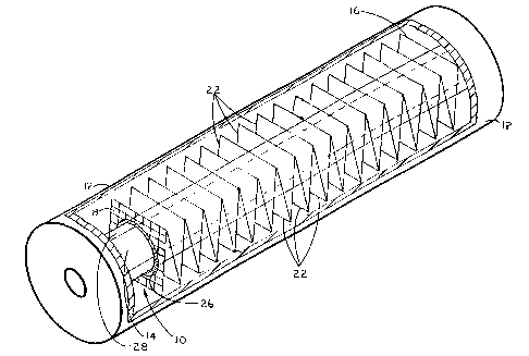
Reference is now made to Figure 1 wherein the subject photocatalytic
reaction enhancement device is depicted and designated generally by reference
numeral 10. The subject device 10 is intended for installation within a
conventional
UV reaction
8a
CA 02404249 2002-09-20
WO 01/70396 PCT/USO1/09051
chamber 12 which houses a UV source 14. The UV light sources applicable to
this
invention are, among others, low-pressure and medium pressure bulbs, broad-
band
pulsed zenon; narrow-band excimer, pulsed electric field, black light and
fluorescent
light that provide an UV spectra in the 100-400 nm range. In the instant case,
UV
source 14 is a UV bulb. The subject apparatus is uniquely designed to be
removably
installed into conventional and other existing UV reaction chambers without
modification
thereof and without the use of invasive mounting means. Neither chamber 12 nor
UV
source 14 form a part of the invention.
The photocatalytic reaction enhancement device of the subject invention
comprises in general, a length of catalyst coated, fluid permeable fixed-
substrate
material 16. With regard to its composition, any or combinations of a metal,
ceramic,
glass or polymeric material are appropriate. There are two preferred
compositions.
The first is a metallic substrate that is either pure or alloyed form of
titanium or tungsten
that is oxidized or anodized to form a titanium dioxide or tungsten oxide
layer,
respectively, or a corrosion-resistant metal alloy that can be coated with the
photocatalyst. Examples of corrosion resistant metals include aluminum,
stainless steel
(300 and 400 series), nickel, tantalum, titanium and zirconium.
The second preferred composition is a glass, polymer or ceramic composition
modified with micropores, channels, or conduits to allow for fluid injection
(Figure 6).
When an oxidizing, reducing agent, or pH control agent supply is connected to
the
apparatus, the agent can be introduced at the photocatalytic surface to
provide more
efficient mass transfer and chemical reactions. Also, a glass, ceramic or
other UV
transmissible substrate 16 allows for light diffraction throughout its
geometry to provide
additional UV transmission to the catalyst surfaces, thus enhancing the
photocatalytic
reactions. Typical oxidants are air, oxygen, ozone and persulfate. Reducing
agents
can be organic solutions/gases or metal-containing solutions/gases. Preferred
reducing
agents are organic based acids that provide the reducing capability of metals
in the
redox reactions, while lowering pH in the solution.
The novel structure and configuration of the substrate each serve to optimize
both photocatalyst surface area and turbulence of the target fluid medium
within the
maximum UV illumination area of the reaction chamber, thereby enhancing
photocatalytic reactivity when the surface of the substrate is subjected to a
light source
9
CA 02404249 2005-04-07
containing UV spectra in the 100 - 400 nm w;3velength band. Structurally,
substrate
16 may be a plain, twill, or micron woven mesh, a filter cloth, extended metal
grating, perforated panels or an aggregate of chopped fibers impregnated in a
polymer, ceramic, or glass. The preferred morphologies are the plain or twill
weaves because their grid-like mesh stru~~ture is conducive to more uniform
application of the photocatalytic coating composition, and their relatively
large open
areas maximize UV illumination within the chamber 12 while minimizing
inorganic
and organic matter fouling. The permeable nature of substrate 16 causes
changes
in fluid dynamics to induce turbulence within the illumination area of the
chamber.
Increased turbulence promotes better mass; transfer of the species in the bulk
medium being treated onto the substrate surface, thus allowing for more
intimate
contact with the catalyst, but does not induce pressure drop or induce fouling
of the
apparatus due to the relatively large open areas of the substrate. Preferred
mesh
sizes range from USS 4x4 to 400x400. The design may also include alternating
mesh sizes to induce better mass transfer or to enhance structural support.
With regard to overall configuration, :substrate 16 is cut to an application-
specific length and then folded in accordion-like fashion to form a plurality
of panels
18 connected in series. Each panel 18 is adapted with at least one aperture 20
for
the slidable reception of UV source 14 there through. Accordingly, each
aperture 20
is sized to snugly accommodate the diameter of the UV source. Some reaction
chambers use more than one light sourcf~ (i.e. multiple bulbs). It should be
appreciated that each panel may include muli:iple apertures to receive the
multiple
light sources there through. For instance, if a chamber employs four UV bulbs,
each panel 18 may have four corresponding apertures 20 oriented to receive the
bulbs.
Each panel 18 has top and bottom edges 22 created by the folding which
serve as hinges to permit slidable adjustment of the substrate along the
length of
UV source 14. As indicated above, substrate 16 may be comprised of a variety
of
materials. In some instances, the composition may be too rigid or brittle to
permit
folding. In such instances, individual panels 18 may be formed by cutting and
then
joined to one another via hinge or other connection means. Alternatively, the
panels
may remain independent of one another and incrementally or randomly spaced
along the length of the UV source. Some applications of the subject device may
call
for a more rigid
CA 02404249 2002-09-20
WO 01/70396 PCT/USO1/09051
composition. For instance, a more rigid composition may be desired,
particularly with
high fluid velocities that would otherwise distort the substrate's shape or
disturb its
positioning relative to the UV source. A more flexible composition may be
preferred to
facilitate cleaning of the UV source while in-service (see below).
Each panel 18 can be cut, molded or otherwise shaped into any geometric
configuration that either fits the contour of the interior surface 24 of UV
chamber 12, or
produces the best efficiency of mass transfer. Examples are depicted in
Figures 2A
through 2D and include a circle, a square, polyhedron and rectangle,
respectively.
Each panel 18 of substrate 16 may be shaped with a different geometry to
accommodate irregular interior surfaces of UV chambers such as those which
employ
internal baffles (not shown). The longest distance d of each panel 18 should
be slightly
less then the interior diameter of the UV chamber to avoid physical contact
between the
two since said surfaces may be prone to scratching.
Referring once again to Figure 1, the edges of each aperture 20 may be
optionally modified with a collar 26 to prevent damage to the scratch-prone
outer
surface of the UV source as well as to actually clean the surface as described
in greater
detail below. Alternatively, a UV transmissive sleeve 28 may be employed
between the
surface of UV source 14 and the subject invention.
Collars 26 are constructed of a glass, composite, or polymeric material that
is
preferably UV, photocatalytic, and heat resistant, while not inducing
sufficient friction
to cause abrading of sleeve 28 or UV source 14. Examples include teflon, PVDF,
acrylic and silica. The material should also preferably provide for UV
transmission.
Collars 26 may also act as cleaning tools that produce a "squeegee-like"
effect as they
ride along the length of UV source 14 or sleeve 28 during manual contraction
and
extension of substrate 16. As collars 26 travel across the UV source surface,
they
loosen scaling and organic material build-up.
Sleeve 28 may be a continuous design along the entire length of the apparatus,
or constructed of smaller individual pieces. The materials of construction of
the sleeve
should allow at least 85% UV transmission, particularly in the range of 100-
400 nm.
The materials should also be heat and UV resistant. Example materials are
quartz
glass, silica glass or silicon dioxide, polyvinlydiene (PVDF), and acrylic.
11
CA 02404249 2002-09-20
WO 01/70396 PCT/USO1/09051
Figures 3A and 3B depict the subject device 10 in contracted and extended
configurations, respectively. It may by readily appreciated that surface area
of
substrate 16 is proportionate to the number of panels present over a given
length of the
UV source. Surface area increases as the number of panels over said length
increases. Over-contraction ofthe accordion-like substrate, however, may
impede fluid
flow through the system. Additionally, over-contraction will reduces
penetration of UV
light onto the front and back surfaces of each panel 18. It is therefore
desirable that
each panel 18 be oriented for maximum penetration of UV light onto its
surfaces. A
range of approximately six to ten (6-10) panels per linear inch of UV source
is preferred.
Alternatively, proper panel orientation may be determined relative to the UV
source
surface. Angles approximating 55-80 degrees relative to the UV surface are
preferred
(Figure 3B) although this range may vary t 10 degrees.
Referring now to Figure 4, a main objective of the subject device is to
increase
catalyst surface area in the locale of the highest available UV illumination
intensity
(closest to the bulb or other UV source). The structure and configuration of
substrate
16 also assist mass transport of the chemical species in the fluid to catalyst
surface due
to induced turbulence caused by fluid flow interruptions. While not intended
to be a
detailed depiction of the fluid dynamics within the chamber 12, Figure 4 does
generally
illustrate the path of fluid flow therein. The angulated configuration of
substrate 16 acts
to "pull" fluid in towards the surface of UV source 14 where light intensity
is believed to
be the greatest. Internal baffles 30 may also assist in this regard and
increase
turbulence. Organic material build-up on UV sources) 14 should be minimized by
the
subject device. Because catalyst-treated substrate 16 is directly proximate to
UV
sources) 14, reactivity (elimination) of the organic material on the source is
enhanced.
As should readily be apparent, the use of substrate 16 alone (without a
catalyst) will
also enhance photolytic reactivity.
Attention now being invited to Figures 6A and 6B, substrate 16 may be further
modified to provide increased turbulence within the chamber, beyond that
provided by
the permeable structure of the substrate and its angulated configuration. A
plurality of
turbulence enhancement means 32 are attached to or integrally formed with
substrate
' 16. These curved or bent extension arms project outwardly from the
substrate's edges
to cause swirling effects that direct fluid from the outer edges of the
reactor into its
12
CA 02404249 2002-09-20
WO 01/70396 PCT/USO1/09051
middle, in closer proximity to UV source 14, thereby mimicking a static mixer.
Turbulence enhancement means 32 may be situated within the same plane as the
panel from which they extend and/or may be bent forward or rearward out of
plane.
The object is to facilitate "pulling" of fluid towards the surface of the UV
sources)
where their energy levels are the highest.
The catalyst formulation is based on a semiconductor material whose Energy
Gap, Eg, is within the range of typical UV spectra, namely between 100-400 nm.
The
catalyst will be of a semiconductor material such as Ti02, ZnO, W03, CdS,
Fe203,
MnOZ, Ce02, CuO, or various titanate-based compounds compatible with the
process
(RTi03 compounds where R is Sr, Ba, Ca, AI or Mg) and may be metallized with
any
individual or combination of the following metals, Pt, Pd, Au, Ag, Re, Rh, Ru,
Fe, Cu,
Bi, Ta, Ti, Ni, Mn, V, Cr, Y, Sr, Li, Co, Nb, Mo, Zn, Sn, Sb or Al. These
metals enhance
the photocatalytic reactions by either reducing or oxidizing species to their
desired form
such as, for example, reducing oxygen to peroxides. In addition to, or as an
alternative
to metallizing the semiconductor, the catalyst may also be doped with any
individual or
combination of f-Transition elements of the Lanthanide or Actinide series such
as Ce,
La, Nd and Gd to stimulate the redox reactions.
The preferred combination of photocatalyst is comprised of titanium dioxide
(Ti02), platinum (Pt), cerium (Ce), and lanthanum (La). When Ti02 is selected,
its
composition should be 50% orgreater concentration of anatase titanium dioxide
crystal,
preferably 70-100%, with the balance either rutile and/or amorphous. The
preferred Pt,
Ce, and La concentrations are 1-5 wt.%, 1-5 wt.% and 1-5 wt.%, respectively.
Pt has
extensive reference to photocatalytic doping. Ce has been studied as a
catalyst for
non-photocatalytic reactions, but in this instance, it provides another metal
for oxidation
reactions. The purpose of the La is to enrich the oxygenating capability of
Ce.
Coating of the substrate with the catalysts) may be performed by several
methods customary in the art, such as by low-temperature sol-gel followed by
calcination or drying, or both, chemical or physical vapor deposition methods
(CVD and
PVD, respectively), chemical vapor infiltration method, low-temperature DC
reactive
sputtering method, anodization of pure titanium or its alloys, direct
oxidation of titanium
or tungsten metals or their alloys through heating in oxygenated environments,
or
through irradiation of organic or aqueous precursors with UV light. Three
preferred
methods are described in greater detail below.
13
CA 02404249 2005-04-07
The first preferred method is low temperature reactive RF magnetron
sputtering, a form of PVD, that has not bef;n detailed in previous patents,
most
probably due to the limitations on its technology. Recent improvements allow
for
more controlled coatings that are applied in a cylindrical versus a planar
cathode.
The process parameters associated with magnetron sputtering can be controlled
to
form different morphologies that cannot be attained through the sol-gel or
other
methods common in the art. A desired morphology is columnar versus a porous
surface. A columnar surface has repeating "cells" of the catalyst of finite
depths.
This is important to the surface reactions :since the pore diffusion
resistance is
reduced. Also, the coating is more evenly dispersed since the substrate
receives
atoms as opposed to particles of the target material. In addition, targets
comprised
of dopant materials can be sputtered onto them substrate after achieving the
desired
semiconductor film to provide the desired composition.
The second method is low-temperature sol-gel process followed by drying.
This method is discussed in U.S. Patent No. 5,501,801 issued to Zhang et al.
The
Pt, Ce, and La can be photo-reduced (Reference US Patent No. 4,303,486, Bard
et
al) onto the resulting sol-gel produced titanic, Note that the Bard et al
patent does
not discuss Ce or La. Pt can be supplied as any aqueous or crystalline form.
The
Ce and La can be supplied in their respective solution or crystalline forms.
Preferred forms are acetate, sulfate, nitrate or chloride.
The third preferred method is irradiation of a fluid composition containing
one or all of the photocatalytic constituents, i.e. Ti02, Pt, Ce or La. This
method is
provided in US Patent 5,593,737 (Meinzer et al). An apparatus is subjected to
a
conditioned solution containing titanium dioxide powder and UV illumination to
form
the titanium dioxide layer onto the apparatus surface. This patent discusses
only
titanium dioxide. The subject method involves either commercially produced
Ti02
powders or sol-gel formed Ti02 powders that are doped with Pt, Ce, and La via
photoreduction as previously addressed. The Ti02 powders are preferred to be
70-
100% anatase with the balance rutile or amorphous, or both. In addition, the
subject method uses the standard UV chamk~er to allow for in-situ coating
without
the need for separate equipment for coatinci application. In addition, the
subject
apparatus may be re-coated (re-generated) in-situ after a designated period
without
the need to be removed from the UV chamber.
14
CA 02404249 2002-09-20
WO 01/70396 PCT/USO1/09051
Although the present invention has been described with reference to the
particular embodiments herein set forth, it is understood that the present
disclosure has
been made only by way of example and that numerous changes in details of
construction may be resorted to without departing from the spirit and scope of
the
invention. Thus, the scope of the invention should not be limited by the
foregoing
specifications, but rather only by the scope of the claims appended hereto.