Note: Descriptions are shown in the official language in which they were submitted.
CA 02404294 2002-09-23
WO 01/73146 PCT/USO1/08933
-1-
CEMENTED CARBIDE TOOL AND METHOD OF MAKING
CROSS-REFERENCE TO EARLIER PATENT APPLICATION
This patent application is a continuation-in-
part to pending United States Patent Application Serial
No. 09/543,710 filed on March '24, 2000 for a CEMENTED
CARBIDE TOOL AND METHOD OF MAKING by Liu et al.
FIELD OF THE INVENTION
The invention pertains to a method of making
a cemented carbide cutting tool, as well as the
cemented carbide cutting tool itself.
BACKGROUND OF THE INVENTION
There are cemented carbide (e. g., tungsten
carbide-based materials with a cobalt binder) cutting
inserts that exhibit a surface zone of non-stratified
binder enrichment such as disclosed in U.S. Patent No.
4,610,931 (and U.S. Reissue Patent No. 34,180) to
Nemeth et al. and U.S. Patent No. 5,955,186 to Grab.
U.S. Patent No. 4,548,786 to Yohe discloses a
process for making a cemented carbide cutting insert
with surface binder enrichment wherein a dewaxed blank
that does not contain nitrogen is exposed during the
heating process to an atmosphere with a nitrogen
partial pressure. PCT Patent Publication No. 98/16665
to Lindskog et al. discloses a cemented carbide cutting
insert with surface binder enrichment which uses a
nitrogen atmosphere for a part of the process.
European Patent No. 0 569 696 to Uchino et al. pertains
to a cemented carbide cutting insert that contains
zirconium and/or hafnium and has a zone of surface
binder enrichment underneath the cutting edge.
European Patent No. 0 603 143 to Gustafson et al.
discloses a method for producing a coated cemented
carbide with a zone of stratified binder enrichment
that includes sintering a compacted body containing
CA 02404294 2002-09-23
WO 01/73146 PCT/USO1/08933
-2-
nitrogen in an inert atmosphere (or a vacuum) followed
by a cooling at a specific rate.
Kennametal KC850 grade coated cutting insert
(KC850 is a registered trademark of Kennametal Inc. of
Latrobe, Pennsylvania, USA, for cutting inserts) has a
zone of stratified binder enrichment. The Nemeth et
al. article entitled "The Microstructural Features and
Cutting Performance of the High Edge Strength
Kennametal Grade KC850", Proceedings of Tenth Plansee
Seminar, Reutte, Tyrol, Austria, Metalwerke Plansee
A.G. (1981), pages 613-627 describes the Kennametal
KC850 grade cutting insert. The article by Kobori et
al. entitled "Binder Enriched Mayer Formed Near the
Surface of Cemented Carbide", Funtai oyobi Funtai
Yakin, Vol. 34, No. 3, pages 129-132 (1987) describes
stratified binder enrichment.
Other articles discuss the occurrence of a
zone of binder enrichment in cemented carbides. These
articles include Schwarzkopf et al., "Kinetics of
Compositional Modification of (W,Ti)C-WC-Co Alloy
Surfaces", Materials Science and Engineering, A105/106
(1988) pages 225-231, Gustafson et al., "Binder-Phase
Enrichment by Dissolution of Cubic Carbides", Int. J.
of Refractory Metals & Hard Materials, 12 (1993-1994),
pages 129-136, Suzuki et al., "The B-Free Layer Formed
Near the Surface of Sintered WC-B-Co Alloy Containing
Nitrogen", Nippon Kinzoku Gakkaishi, Vol. 45, No. 1
(1981), pages 95-99, and Suzuki et al., "The B-Free
Layer Formed Near the Surface of Vacuum-Sintered WC-B-
Co Alloys Containing Nitrogen", Transactions of the
Japan Institute of Metals, Vol. 22, No. 11 (1981),
pages 758-764.
While some of the above articles, patents and
products disclose or comprise cutting inserts that
exhibit adequate performance, there remains a need to
develop processes that produce products (and the
products themselves) that have better properties. In
CA 02404294 2002-09-23
WO 01/73146 PCT/USO1/08933
-3-
this regard, it would be desirable to provide a process
(and the resultant product) that sinters the blank in
an atmosphere most always having at least a partial
pressure so as to be able to control the depth of the
zone of binder enrichment. Such a process would
provide for an optimum balance between the edge
strength and the deformation resistance of the
substrate. Such a process would also provide for
excellent consistency in the depth of the zone of
binder enrichment for the parts throughout.a heat.
It would also be desirable to provide a
process, as well as the resultant product, wherein
there is no carbon precipitation in the zone of binder
enrichment, especially in a substrate that. has a core
porosity of greater than C00 according to ASTM
Designation B276-91 (Reapproved 1996). The absence of
such carbon precipitation would enhance the adhesion of
the coating to the substrate.
It would be advantageous to provide an as-
sintered cemented carbide that exhibits a surface zone
of non-stratified binder enrichment (or essentially
non-stratified binder enrichment which means that most
of the binder enrichment is of the non-stratified type
with a slight (or small) amount of stratified binder
enrichment) wherein there is enhanced solid-solution
hardening. In this regard, a cemented (cobalt)
tungsten carbide substrate that has nitrogen atoms
present at the interstices of the cobalt atoms
facilitates solid-solution hardening. The enhancement
of solid-solution hardening is especially true for a
substrate that with a bulk region that exhibits a
porosity of greater than C00 according to ASTM
Designation B276-91 (Reapproved 1996). In such a case,
the atomic radius of nitrogen (about 0.75 Angstroms)is
smaller than the atomic radius of carbon (about 0.91
Angstroms).
CA 02404294 2002-09-23
WO 01/73146 PCT/USO1/08933
-4-
It would be advantageous for applying a
coating, and especially a coating that contains
nitrogen (e. g., titanium nitride or titanium
carbonitride), directly on the surface of a substrate
that contains nitrogen. In the case of the application
of a coating of titanium nitride on the surface of a
substrate that has bulk region with a porosity of not
greater than C00 according to ASTM Designation B276-91
(Reapproved 1996), the presence of nitrogen would
promote nucleation of titanium nitride. In the case of
the application of titanium carbonitride to the surface
of a substrate with a bulk region exhibiting a porosity
of greater than C00 according to ASTM Designation B276-
91 (Reapproved 1996), the presence of carbon and
nitrogen would help promote the nucleation of titanium
carbonitride.
It is believed that with the presence of
additional nitrogen in the cobalt binder for a cemented
(cobalt) tungsten carbide substrate that has a surface
zone of cobalt enrichment, there is an increase in the
chemical affinity between the substrate and a nitrogen-
containing coating, such as, for example, titanium
nitride or titanium carbonitride. It is believed that
such an increase in the chemical affinity should lead
to an increase in the adhesion of the coating to the
substrate.
It is believed that an increase in the
availability of nitrogen in the cobalt near the surface
of the substrate should reduce the potential for the
formation of a brittle eta phase at the interface
between the coating and the substrate. The reduction
in the potential to form eta phase permits the use of
substrates that have lower carbon contents.
It is believed that a higher nitrogen content
in the substrate should also result in a decrease in
the grains size of the tungsten carbide. An increase
in the N/(C+N) content should lead to a decrease in the
CA 02404294 2002-09-23
WO 01/73146 PCT/USO1/08933
-5-
grain size of the tungsten carbide. The tungsten
carbide phase content in the microstructure should
increase to a maximum as the N/(C+N) ratio increases.
It can thus be seen that there is a belief
that it would be advantageous to provide an as-sintered
cemented (cobalt) tungsten carbide substrate that has a
higher nitrogen content. The higher nitrogen content
should increase adhesion strength between the coating
(especially a coating such as titanium nitride and
titanium carbonitride) and the substrate. The higher
nitrogen content in the cobalt binder near the surface
of the substrate should reduce the potential for the
formation of brittle eta phase at the coating-substrate
interface. The higher nitrogen content should decrease
the grain size of the tungsten carbide.
Typically, it has been necessary to use
different compositions of the starting powder to
produce either an as-sintered substrate that exhibits a
surface zone of binder enrichment or an as-sintered
substrate in which there is an absence of a surface
zone of binder enrichment. As can be appreciated,
there is an increase in the cost associated with
storing (and/or making) two or more different
compositions of starting powder as compared with the
cost of storing (and/or making) only one composition of
starting powder. From a production viewpoint, it would
advantageous to provide a process that would utilize a
single starting powder composition to selectively
produce either an as-sintered substrate of a commercial
quality with a surface zone of binder enrichment or an
as-sintered substrate of a commercial quality that does
not have a surface zone of binder enrichment.
SUMMARY OF THE INVENTION
In one form, the invention is a coated
cutting insert that includes a tungsten carbide-based
substrate with rake and flank surfaces and a cutting
CA 02404294 2002-09-23
WO 01/73146 PCT/USO1/08933
-6-
edge at their intersection. The substrate, which has a
porosity rating according to ASTM Designation B276-91
(Reapproved 1996) of greater than C00, has a surface
zone of non-stratified binder enrichment that does not
exhibit any carbon precipitation. There is a coating
on at least a part of the substrate.
In another form thereof, the invention is a
method of making a coated tungsten carbide-based
cutting insert wherein starting powders are mixed,
pressed into a green blank which is then dewaxed. The
dewaxed blank is subjected to a sinter heating step, a
sinter holding step and a controlled cooling step
wherein all of these steps occur in their entirety in
an atmosphere that has a partial pressure and for at
least a part of the duration of the sinter heating step
and the sinter holding step the atmosphere contains a
nitrogen partial pressure. The as-sintered substrate
is then coated with one or more layers.
In still another form thereof, the invention
is a cemented (cobalt) tungsten carbide-based substrate
made by sintering a mass of compacted powders in an
atmosphere that contains at least a partial pressure.
The substrate has rake and flanks surfaces that have a
cutting edge at their intersection. The substrate has
a zone of non-stratified cobalt enrichment that is
adjacent to and extends inwardly from the cutting edge
and at least one of the rake and flank surfaces toward
the bulk substrate, which has a porosity of greater
than C00. The zone of cobalt enrichment does not
exhibit any carbon precipitation and has a maximum
cobalt content between about 125 and about 300 percent
of the bulk cobalt content.
Iri yet another form thereof, the invention is
a made by sintering a compacted mass of starting
powders in an atmosphere having at least a partial
pressure wherein the starting powders containing the
following components: cobalt, tungsten, carbon,
CA 02404294 2002-09-23
WO 01/73146 PCT/USO1/08933
_7_
titanium, niobium and tantalum, the substrate
comprising: a peripheral surface defined by a rake
surface, a flank surface, and a cutting edge at the
intersection of the rake and flank surfaces the
substrate having a zone of non-stratified cobalt
enrichment beginning adjacent to and extending inwardly
from the cutting edge and at least one of the rake
surface and the flank surface toward a bulk region, the
bulk region having a porosity according to ASTM
Designation B276-91 (Reapproved 1996) of greater than
C00; the zone of cobalt enrichment being at least
partially depleted of the solid solution carbides
and/or solid solution carbonitrides; the zone of cobalt
enrichment not exhibiting any carbon precipitation and
the zone of cobalt enrichment having a cobalt content
between about 125 percent and about 300 percent of the
cobalt content of the bulk region.
In still another form thereof, the invention
is a coated cutting insert that comprises a
substantially fully dense substrate made by sintering a
compacted mass of starting powders in an atmosphere
containing a nitrogen partial pressure. The starting
powders include the following components: a binder
selected from one or more of cobalt, nickel, iron and
their alloys wherein the binder is present between
about 3 weight percent and about 12 weight percent, up
to about 95 weight percent tungsten, up to about 7
weight percent carbon, and up to about 13 weight
percent of one or more of the following components:
titanium, tantalum, niobium, hafnium, zirconium, and
vanadium. The substrate has a rake surface and a flank
surface, and there is a cutting edge being at the
intersection of the rake and flank surfaces. The
substrate has a zone of non-stratified binder
enrichment of a generally uniform depth beginning
adjacent to and extending inwardly from the cutting
edge and at least one of the rake surface and the flank
CA 02404294 2002-09-23
WO 01/73146 PCT/USO1/08933
-g_
surface toward a bulk region. The zone of binder
enrichment has a high nitrogen content, and the bulk
region of the substrate has a high nitrogen content.
There is a coating,on the cutting edge and at least a
portion of one or both of the rake surface and the
flank surface of the substrate.
In another form thereof, the invention is a
method of making a coated cemented carbide cutting
insert comprising the steps of: blending starting
powders to form a starting powder mixture wherein the
powders contain the following components: a binder
selected from one or more of cobalt, nickel, iron and
their alloys, tungsten, carbon, and one or more of the
following: titanium, tantalum, niobium, hafnium,
zirconium, and vanadium pressing the starting powder
mixture to form a green cutting insert blank; dewaxing
the green cutting insert blank to form a dewaxed
cutting insert blank; sinter heating the dewaxed
cutting insert blank from about the maximum dewaxing
temperature to at least a pore closure temperature in
an atmosphere having a first nitrogen partial pressure
for substantially the entire sinter heating step so as
to form a pre-sintered cutting insert blanks sinter
holding the pre-sintered cutting insert blank at a
sinter hold temperature in an atmosphere having a
second nitrogen partial pressure for substantially the
entire sinter holding step to form a sintered cutting
insert blank wherein~the second nitrogen partial
pressure is greater than the first nitrogen partial
pressures cooling the sintered cutting insert blank
from the sintering temperature to a target temperature
below the eutectic temperature so as to form an as-
sintered cutting insert substrate having a peripheral
surface with a zone of non-stratified binder enrichment
beginning adjacent to and extending inwardly toward a
bulk region of the substrates and coating the as-
sintered cutting insert substrate with a coating
CA 02404294 2002-09-23
WO 01/73146 PCT/USO1/08933
-9-
comprising one or more layers including a base layer on
the surface of the substrate, and the base layer
comprising a material containing nitrogen.
In still yet another form thereof, the
invention is a method of selectively making either as
as-sintered substrate that exhibits a surface zone of
binder enrichment or an as-sintered substrate that does
not exhibit a surface zone of binder enrichment, the
method comprising the steps of: blending starting
powders with an effective amount of nitrogen being
absent and containing a binder alloy selected from one
or more of cobalt, nickel, iron and their alloys,
tungsten, carbon, and one or more of the following:
titanium, tantalum, niobium, hafnium, zirconium, and
vanadium pressing the starting powder mixture to form
a green cutting insert blank;~dewaxing the green
cutting insert blank to form a dewaxed cutting insert
blank; sinter heating the dewaxed cutting insert blank
from the maximum dewaxing temperature to at least a
pore closure temperature in an atmosphere having a
first nitrogen partial pressure for substantially all
of the entire sinter heating step so as to form a pre-
sintered cutting insert blanks sinter holding the pre-
sintered cutting insert blank at a sinter hold
temperature in an atmosphere having a second nitrogen
partial pressure for substantially the entire sinter
holding step as to form a sintered cutting insert blank
and wherein the second nitrogen partial pressure may
selectively be either greater than equal to or less
than the first nitrogen partial pressure; cooling the
sintered cutting insert blank from the sintering
temperature to a target temperature below the eutectic
temperature so as to form an as-sintered cutting insert
substrate wherein when the second nitrogen partial
pressure is greater then the first nitrogen partial
pressure the as-sintered cutting insert substrate does
not exhibit a surface zone of binder enrichment and
CA 02404294 2002-09-23
WO 01/73146 PCT/USO1/08933
-10-
when second nitrogen partial pressure is equal to or
less than the first nitrogen partial pressure the as-
sintered cutting insert substrate exhibits a surface
zone of binder enrichment; and coating the as-sintered
cutting insert substrate with a coating comprising one
or more layers.
BRIEF DESCRIPTION OF THE DRAWINGS
The following is a brief description of the
drawings which form a part of this patent application:
FIG. 1 is an isometric view of a specific
embodiment of an SPGN 432 style of cutting insert;
FIG. 2 is a cross-sectional view of the
cutting insert of FIG. 1 taken along section line 2-2
of FIG. 1;
FIG. 3 is an isometric view of a specific
embodiment of an SNG 433 style of cutting insert;
FIG. 4 is a cross-sectional view of the
cutting insert of FIG. 3 taken along section line 4-4
of FIG. 3;
FIG. 5 is a cobalt profile showing the cobalt
concentration relative to the bulk cobalt concentration
as measured by an energy dispersive x-ray line scan
analysis (EDX) technique at selected distances in
micrometers from the peripheral surface of the as-
sintered cutting insert substrate made according to
Example No. 1 hereof;
FIG. 6 is a photomicrograph (at a
magnification of 1500X) showing the microstructure near
the surface of the as-sintered cutting insert substrate
made according to Example 1 hereof; and
FIG. 7 is a photomicrograph (at a
magnification of 1500X) showing the microstructure near
the surface of the as-sintered cutting insert substrate
made according to Example No. 6 hereof;
FIG. 8 is a photomicrograph (at a
magnification of 1200 X) showing the microstructure at
CA 02404294 2002-09-23
WO 01/73146 PCT/USO1/08933
-11-
the corner of an as-sintered cutting insert substrate
made according to Example 1;
FIG. 9 is a photomicrograph, which has a
distance indicator of 10 micrometers showing the
microstructure near the surface of the as-sintered
cutting insert substrate made according to Example
X207-1. hereof:
FIG. 10 is a photomicrograph, which has a
distance indicator of 10 micrometers showing the
microstructure near the surface of the as-sintered
cutting insert substrate made according to Example
X207-2 hereof and
FIG. 11 a photomicrograph, which has a
distance indicator of 10 micrometers showing the
microstructure near the surface of the as-sintered
cutting insert substrate made according to Example
X207-3 hereof.
DETAILED DESCRIPTION OF THE INVENTION
Referring to the drawing figures, FIG. 1
illustrates a specific embodiment of an indexable
cutting insert generally designated as 20. Cutting
insert 20 has cutting edges 22 at the juncture (or
intersection) of the rake face 24 and the flank faces
26. Although the cutting insert shown in FIG. 1 is an
SPGN 432 style of cutting insert with a honed cutting
edge, applicants contemplate that the present invention
includes other styles of cutting inserts with or
without honed cutting edges.
As illustrated in FIG. 2, the two basic
components of the cutting insert 20 are the substrate
30 and the coating 32 wherein the coating 32 (as shown
by brackets) may comprise one or more layers. The
substrate 30 has a rake surface 36 and flank surface 38
that intersect to form a substrate cutting edge (or
corner) 40. The rake surface 36 and the flank surfaces
38 comprise the peripheral surfaces of the substrate
CA 02404294 2002-09-23
WO 01/73146 PCT/USO1/08933
-12-
30. The substrate 30 has a zone of binder enrichment
42 which begins at the peripheral surfaces thereof and
extends inwardly from the rake surface 36 a distance
"A" (see FIG. 2) and from the flank surface 38 a
distance "B". Although in the specific embodiment of
FIGS. 1 and 2 the zone of binder enrichment extends
from the peripheral surface, applicants contemplate
that in some circumstances the zone of binder
enrichment may extend inwardly beginning near (but not
at [e.g., slightly below]) the peripheral surface of
the substrate.
In the specific embodiment of FIGS. 1 and 2
the distances "A" and "B" are essentially about equal,
but depending upon the application the magnitude of the
distances "A" and "B" may not always be equal. The
zone of binder enrichment extends inwardly from the
cutting edge a distance "C" which is illustrated as
being greater than either distance "A" or distance "B";
however, applicants contemplate that this may not
always be the case. In other circumstances the
distances "A" and "B" each may be greater than distance
"C" or one or the other of the distances "A" and "B"
may be greater than distance "C".
The zone of binder enrichment 42 may comprise
either a non-stratified type of binder enrichment or an
essentially non-stratified type of binder enrichment.
Essentially non-stratified binder enrichment means that
the majority of the enrichment is of the non-stratified
type with a slight presence of stratified binder
enrichment. The non-stratified type of binder
enrichment is generally homogeneous in nature. Non-
stratified binder enrichment is in distinction to
stratified binder enrichment in which the binder forms
as-layers one on top of the other. Stratified binder
enrichment is'a subject of discussion in the earlier
mentioned Kobori et al. article and Nemeth et al.
CA 02404294 2002-09-23
WO 01/73146 PCT/USO1/08933
-13-
article each one of which is hereby incorporated by
reference herein.
In a preferred embodiment, the substrate 30
is a tungsten carbide-based cemented carbide material
containing at least about seventy weight percent
tungsten carbide, and more preferably, at least about
eighty weight percent tungsten carbide. The binder is
preferably cobalt or a cobalt alloy; however, the
binder may comprise iron and/or nickel and their
alloys. When the binder is 'cobalt (or a cobalt alloy),
the preferably cobalt concentration for the bulk
substrate, i.e., the cobalt concentration in the bulk
region of the substrate, is between about three weight
percent and about twelve weight percent. The more
preferably cobalt concentration for the bulk substrate
is between about five weight percent and about eight
weight percent. Even more preferably, the cobalt
concentration for the bulk substrate is between about
5.6 weight percent and about 7.5 weight percent. It
should be appreciated that the specific cobalt content
of the cutting insert will depend upon the specific
application for the cutting insert.
The substrate 30 most preferably also
contains solid solution carbides and/or solid solution
carbonitrides. More specifically, solid solution
carbide and/or solid solution carbonitride forming
elements (e. g., titanium, tantalum, niobium, hafnium,
zirconium, vanadium) form these solid solutions with
each other and/or tungsten. The more preferable
elements for forming solid solution carbides and/or
solid solution carbonitrides are titanium, tantalum,
and niobium. It is preferred that the sum of the
tantalum content and the niobium content is between
about three weight percent and about seven weight
percent, and the titanium content is between about 0.5
weight percent and about five weight percent. Most
preferably, the sum of the tantalum content and the
CA 02404294 2002-09-23
WO 01/73146 PCT/USO1/08933
-14-
niobium content is between about 5.0 weight percent and
about 5.9 weight percent, and the titanium content is
between about 1.7 weight percent and about 2.3 weight
percent.
In one specific embodiment the starting
powder mixture does not contain any effective amount of
nitrogen wherein an effective amount of nitrogen is the
minimum amount of nitrogen that will cause any
measurable (or perceivable) amount of binder enrichment
to occur. Hence, for this embodiment the sole source
of the nitrogen for the formation of any carbonitrides
during the sintering process, and possibly present in
the as-sintered substrate 30, comes from the nitrogen
in the atmosphere to which the substrate is exposed
during the sintering process. However, as described
hereinafter another specific embodiment contains
nitrogen in the starting powder mixture.
In the zone of binder enrichment, the solid
solution carbides andlor carbonitrides have been
wholly, or in some cases partially, depleted so that
the tungsten carbide and the cobalt comprises the
majority (and in some cases all) of the composition of
the zone of binder enrichment. It is generally thought
that a lower level of solid solution carbides andlor
carbonitrides results in an increase in the edge
strength (or toughness).
The zone of binder enrichment also typically
does not contain any free carbon in that there is. an
absence of any carbon flakes (i.e., carbon penetration
or carbon precipitation) in the zone of binder
enrichment. The presence of carbon precipitation in
the zone of binder enrichment may result in poor
adhesion of the coating to the substrate so that the
absence of carbon precipitation is desirable.
In the zone of binder enrichment, the binder
(e. g., cobalt or a cobalt alloy) concentration
preferably should reach a maximum value that is between
CA 02404294 2002-09-23
WO 01/73146 PCT/USO1/08933
-15-
about one hundred twenty-five percent and about three
hundred percent of the binder concentration in the bulk
region of the substrate, i.e., the bulk substrate. A
more preferably range of the maximum level of binder
concentration in the zone of binder enrichment is
between about one hundred fifty percent and about three
hundred. percent of the binder concentration in the bulk
substrate. The most preferable range of the maximum
level of binder concentration in the zone of binder
enrichment is between about two hundred weight percent
and about two hundred fifty weight percent of the
binder concentration in the bulk substrate.
The zone of binder enrichment preferably
begins at and extends inwardly from the peripheral
surfaces) of the substrate. However, in some cases,
there may be a thin layer adjacent to the peripheral
surfaces) in which the binder concentration has been
reduced (or even eliminated) due to binder evaporation.
In such a case, the zone of binder enrichment begins
near the peripheral surface and extends inwardly
therefrom. Applicants consider that the
characterization that the zone of binder enrichment
begins adjacent to the surfaces) means that the zone
of binder enrichment begins either at or near the
surface(s).
The thickness of the zone of binder
enrichment may extend inwardly beginning at or near the
peripheral surface (e. g., the rake surface, the flank
surface, and/or the cutting edge) a distance up to
about fifty micrometers. One preferred range of the
thickness of the zone of binder enrichment is between
about five micrometers and about fifty micrometers. A
more preferred range is between about ten micrometers
and about forty micrometers. The most preferred range
is between about twenty micrometers and about thirty
micrometers. In the selection of the preferred depth
of the zone of binder enrichment one typically balances
CA 02404294 2002-09-23
WO 01/73146 PCT/USO1/08933
-16-
the deformation resistance and the edge strength of the
substrate. The edge strength increases, but the
deformation resistance decreases, with an increase in
the depth of the zone of binder enrichment.
It is desirable to be able to provide a
process for making the as-sintered cutting insert
substrate by which one may control the thickness of the
zone of binder enrichment. By varying the process
parameters (e. g., the magnitude of the nitrogen partial
pressure in the atmosphere, the temperature, the
duration) in conjunction with the composition of the
starting powders one may control the depth of the zone
of binder enrichment both at the flat surfaces (e. g.,
the rake surface and the flank surface) and at the
cutting edges) of the as-sintered cutting insert
substrate.
By controlling the process parameters, one
may also control the depth of the zone of binder
enrichment. It is also believed that control of the
process parameters should control the content of
nitrogen in the substrate. By controlling the nitrogen
content one should be able to provide a substrate that
has a desirably high nitrogen content in the bulk
region thereof and a desirably high nitrogen content in
the surface zone of binder enrichment thereof.
As illustrated in FIGS. 1 and 2, bonded onto
the peripheral surface of the substrate is a hard
coating 32 that has three layers. These layers
comprise the base layer 52 applied directly to the
peripheral surface of the substrate, the intermediate
layer 54 applied to the surface of the base layer 52
and the outer layer 56 applied directly to the surface
of the intermediate layer 54. Although FIG. 2
illustrates that each one of these layers is of a
different thickness, it should be appreciated that
applicants contemplate that the thickness of each
layer, the specific number of layers, and the
CA 02404294 2002-09-23
WO 01/73146 PCT/USO1/08933
-17-
composition of each layer may vary depending upon the
specific application for the cutting insert.
One preferred coating scheme comprises a 4.5
micrometer thick base layer of titanium carbonitride
applied to the surface of the substrate, an 8.5
micrometer thick mediate layer of alumina (alpha)
applied to the surface of the base layer, and a 1.5
thick outer layer of titanium carbonitride and titanium
nitride applied to the surface of the mediate layer
wherein all of the above layers are applied by chemical
vapor deposition (CVD). Another preferred coating
scheme comprises a base layer of titanium nitride that
is 0.5 micrometers thick applied by CVD to the surface
of the substrate, a 7 micrometer thick layer of
titanium carbonitride applied by moderate temperature
chemical vapor deposition (MT-CVD) to the surface of
base layer, a 0.5 micrometer thick layer of titanium
carbonitride applied by CVD to the surface of the MT-
CVD layer of titanium carbonitride, a 4 micrometer
thick layer of alumina (kappa) applied by CVD to the
surface of the CVD titanium carbonitride layer, and a 1
micrometer thick outer layer of titanium nitride
applied by CVD to the surface of the alumina layer.
In addition to the above compositions
exemplary compositions for these layers include
titanium aluminum nitride applied by physical vapor
deposition (PVD), titanium diboride applied by PVD,
titanium carbide, and other materials suitable for use
as a coating for cutting inserts. These coating layers
may be applied by one or more known techniques that
include, without limitation, PVD, CVD and/or MT-CVD
techniques.
As illustrated in FIG. 2, for a cutting
insert 20 used in milling applications it is preferred
that the zone of binder enrichment 42 extend inwardly
from the rake surface 36 and the flank surfaces 38 of
the substrate 30. The zone of binder enrichment 42 is
CA 02404294 2002-09-23
WO 01/73146 PCT/USO1/08933
-18-
generally parallel to the rake surface 36 and the flank
surfaces 38 of the substrate. The zone of binder
enrichment also extends inwardly from the cutting edge
40 of the substrate.
In other material removal applications, such
as, for example, turning, it is preferred that the zone
of binder enrichment is present only at the rake
surface of the substrate, i.e., the zone of binder
enrichment only extends inwardly beginning at or near
the rake surface of the cutting insert substrate. In
such a case, it is typical that the zone of binder
enrichment has been removed by grinding (or the like)
from the other surfaces (e.g., the flank surface) of
the cutting insert substrate after completion of the
consolidation process.
Referring to FIGS. 3 and 4, cutting insert
generally designated as 70 has four flank faces 72
which intersect with one (top) rake face 74 and another
(bottom) rake face to form eight cutting edges 78.
Cutting insert 70 has a substrate generally designated
as 79 (see FIG. 4) with a peripheral surface wherein
the peripheral surface includes a rake surface 80 and a
ground flank surface 82. Substrate 79 has an interior
bulk region 84 which comprises a majority of the volume
of the substrate 79. The substrate 79 further has a
zone of binder enrichment 86 that extends inwardly from
the rake surface 80 of the substrate 79. Any zone of
binder enrichment is absent from any portion of the
bulk region near the flank surfaces 82.
The substrate 79 for the cutting insert 70 is
essentially of the same composition as the composition
of the substrate 30 of the first embodiment of the
cutting insert 20. The levels of binder enrichment in
the zone of binder enrichment 86 are essentially the
same as those levels of binder enrichment that are in
the zone of binder enrichment 42 of the first
embodiment of the cutting insert 20. The basic coating
CA 02404294 2002-09-23
WO 01/73146 PCT/USO1/08933
-19-
scheme, which is shown in brackets 90, is essentially
the same as the coating scheme 32 for the first
embodiment of the cutting insert 20 so as to have a
base layer 92, an intermediate layer 94, and an outer
layer 96.
Applicants do not intend to be held to, or
limited by, the discussion of the following scientific
theory that may be applicable to his invention.
Applicants believe that the depth of the zone of binder
enrichment may be predicted, and hence controlled, by
taking into consideration the composition of the
starting powder and along with the other processing
parameters (e. g., temperature and duration of the hold)
providing an atmosphere having a predetermined nitrogen
partial pressures) for the various stages of the
sintering process which includes the sinter heating,
the sinter holding and the controlled cooling steps.
The magnitude of the nitrogen partial pressure in the
atmosphere for each stage may be determined through a
calculation using Gibbs free energies. The calculation
determines of the equilibrium nitrogen partial pressure
necessary to either permit nitrogen diffusion into the
blank or nitrogen evolution out of the blank. By
providing an atmosphere having a nitrogen partial
pressure per the calculation,~applicants have been able
to control the amount of nitrogen that enters the blank
during the sinter heating stage of the sintering
process, as well as control the extent the nitrogen
evolves from the blank during the sinter holding and
controlled cooling stages of the sintering process, so
as to essentially control the depth of the zone of
binder enrichment in the as-sintered cutting insert
substrate. A brief discussion of the formulas used to
make the above calculation now follows.
Referring to the fundamental basics of the
calculation where for all formulas (1) through (8) "T"
is the temperature in degrees Kelvin, formula (1) set
CA 02404294 2002-09-23
WO 01/73146 PCT/USO1/08933
-20-
forth below expresses the change in the Gibbs free
energy for the reaction of 2TiN = 2 Ti + N2:
OG1° = 161700-45.54T. (1)
Formula (2) set forth below expresses the change in the
Gibbs free energy for the reaction TiC = Ti + C:
OGz° = 44600-3.14T. (2)
The combination of these above two reactions and two
formulas results in formula (3) below for the change in
Gibbs free energy of the reaction 2 TiC + Nz = 2 TiN +
2C to be as follows:
OG3° - -72500 + 39.22T (3)
The following formula (4) expresses the condition when
the reaction 2 TiC + Nz + 2 TiN + 2C reaches
equilibrium:
~G3° - -RT~ lnKp =
-RT~ln ( f a~ ] z~ f aT~rr ] 2 ) / ( f aNZ ] ~ f aT~c ] z ) . ( 4 )
where Kp is the equilibrium constant, ai is the activity
of the "i" component. The data for OG° are taken from
the text by Kubaschewski et al. entitled "Metallurgical
Thermo-Chemistry", 5th Edition, Pergamon Press (1979).
Making the approximation that (aT;,N) / (aT;,c) - 1
and that R = 2 calories/K~mol and equating equations
(3) and (4) above, one arrives at equation (5) set
forth below:
-72500 + 39.22T = -2T~lnKp = -2T~ln (a~z/aNZ) (5)
From equation (5) above one obtains the
following equation (6):
Kp = a~z/aNZ = exp[ (72500/2T)-(39.22/2) ] (6)
In light of the following formula (7):
aNZ = P°N2/P (=1 atm. ) - P°N2 [units are atmospheres]
The following formula (8) thus expresses the
equilibrium partial pressure:
P°N2 = a~z /Kp ( 8 )
What this means is that at a specific
temperature, one may calculate the equilibrium constant
KP. The carbon activity, a~, is a variable in the
cemented carbide blank that is subjected to sintering,
CA 02404294 2002-09-23
WO 01/73146 PCT/USO1/08933
-21-
but ranges between about 0.3 and about 1. By
calculating the equilibrium nitrogen partial pressures
ranging over temperatures between the maximum dewaxing
temperature to the sinter hold temperature, the
formation and depth of the zone of binder enrichment
may be controlled so that the process produces an as-
sintered cutting insert substrate with a zone of binder
enrichment of a pre-selected depth.
The process typically comprises the following
processing steps.
First, the powder mixture is thoroughly
blended (or mixed) together along with a fugitive
binder by a process such as ball milling. In one
embodiment the starting powder does not contain an
effective amount of nitrogen. In another embodiment
the starting powder contains an effective amount of
nitrogen typically added as an additive such as
titanium nitride. The powder blend is then pressed
into a green cutting insert blank. The green cutting
insert blank has partial density (e. g., about fifty-
five percent) and open porosity.
Next, the green cutting insert blank is
subjected to a dewaxing (or delubing) step by heating
(typically in an atmosphere with a hydrogen partial
pressure or sometimes in an atmosphere with a positive
hydrogen pressure) from ambient temperature to a
maximum dewaxing temperature so as to evaporate the
fugitive binder from the blank and thereby form a
dewaxed cutting insert blank. In this patent
application the term "partial pressure" means a
pressure of less than one atmosphere and the term
"positive pressure" means a pressure of greater than
one atmosphere. Although these parameters may vary, a
typical heating rate is 2.78 degrees Centigrade per
minute and a typical maximum dewaxing temperature is
about 450 degrees Centigrade.
CA 02404294 2002-09-23
WO 01/73146 PCT/USO1/08933
-22-
As an optional next step, the dewaxed cutting
insert blank may undergo a hold (e.g., ten minutes in
duration) under a vacuum at the maximum dewaxing
temperature.
The next step is to subject the dewaxed
cutting insert blank to a sinter heating step by
heating the blank at a typical rate of 2.78 degrees
Centigrade per minute from the maximum dewaxing
temperature, past the temperature where the blank
exhibits closure of the continuous porosity, and to the
maximum sintering temperature which typically is about
1483 degrees Centigrade. Although the specific
parameters depend upon the composition of the starting
powders (and especially the carbon level and the
extent, if any, to which there is nitrogen therein)
all, or possibly part of, the sinter heating step
occurs for a predetermined duration through a pre-
selected temperature range in an atmosphere with a
selected nitrogen partial pressure. The nitrogen
partial pressure may typically range between about
fifteen torr and about seventy torr; however, too high
of a nitrogen partial pressure may cause too much
nitrogen gas to diffuse into the blank so as to
adversely affect the ability to achieve a closed
continuous porosity. As a result of the sinter heating
step, the dewaxed cutting insert blank is transformed
into a pre-sintered cutting insert blank that contains
nitrogen, which typically is a pre-selected amount of
nitrogen.
Applicants believe that by heating the
dewaxed cutting insert blank in an atmosphere with a
nitrogen partial pressure, nitrogen is able to diffuse
into the dewaxed cutting insert blank so long as there
is both open porosity and a favorable nitrogen
concentration gradient between the blank and the
atmosphere so as to permit such diffusion. As the
sinter heating step continues under nitrogen partial
CA 02404294 2002-09-23
WO 01/73146 PCT/USO1/08933
-23-
pressure the nitrogen continues to diffuse throughout
the mass of the cutting insert blank. By the time the
temperature reaches the point where there is closure of
continuous open porosity in the blank, the nitrogen
content is generally uniform throughout the mass of the
pre-sintered cutting insert blank.
In the embodiment where an effective amount
of nitrogen is absent from the starting powders
essentially all of the nitrogen contained in the pre-
sintered cutting insert blank comes from the atmosphere
of the sinter heat step. In the embodiment where the
starting powder mixture contains an effective amount of
nitrogen, only some of the nitrogen contained in the
pre-sintered cutting insert blank comes from the
atmosphere of the sinter heat step. Typically, the
nitrogen forms solid solution carbonitrides with the
carbonitride-forming elements such as titanium,
tantalum, niobium, zirconium, hafnium and vanadium~that
may be in the pre-sintered cutting insert blank wherein
titanium, tantalum and niobium are the preferred
carbonitride-forming elements.
When the starting powder-mixture contains
nitrogen it is possible that the atmosphere during the
sinter heating step may not contain any nitrogen
partial pressure or may only have a nitrogen partial
pressure for a part of this step. However, the
atmosphere should have a partial pressure throughout
the sinter heating step so as to not permit the
uncontrolled evolution of nitrogen from the blank.
One may also be able to control the depth of
the surface zone of binder (cobalt) enrichment by
varying the ramp rate of the sinter heating step.
Typically, a decrease in the ramp rate during the
sinter heating step when done under a nitrogen partial
pressure increases the depth of the surface zone of
binder enrichment. An increase in the ramp rate during
the sinter heating step when done under a nitrogen
CA 02404294 2002-09-23
WO 01/73146 PCT/USO1/08933
-24-
partial pressure typically decreases the depth of the
surface zone of binder (cobalt) enrichment.
After completion of the sinter heating step,
the pre-sintered cutting insert blank is subjected to a
sinter holding step wherein the blank is held at the
maximum sintering temperature for a predetermined
duration. For all, or at least a part, of the sinter
holding step the atmosphere contains a nitrogen partial
pressure. During the sinter holding step the nitrogen
in the pre-sintered cutting insert blank evolves from
the blank. The nitrogen evolution is thought to
facilitate the formation of the zone of binder
enrichment beginning at (or near) the peripheral
surface of the blank and extending inwardly toward the
bulk substrate.
The duration of the sinter holding step, the
maximum sintering temperature, the magnitude of the
nitrogen partial pressure during the sinter heating
step, and the magnitude of the nitrogen partial
pressure during the sinter holding step each can play a
role in controlling the depth of the zone of binder
enrichment. The result of the sinter holding step is a
sintered cutting insert blank that exhibits a zone of
non-stratified binder enrichment of a controlled depth.
By controlling the parameters of the sinter
heating step and the sinter holding step, it is
believed that one may also control the nitrogen
concentration in the bulk region and the surface zone
of binder enrichment of the substrate, as well as
control the depth of the surface zone of binder
enrichment. As mentioned herein, it is applicants'
belief that the presence of nitrogen in the surface
zone of binder (cobalt) enrichment provided certain
advantages.
As an option, applicants contemplate that
once the pre-sintered cutting insert blank reaches a
liquid phase stage during the sinter holding step, the
CA 02404294 2002-09-23
WO 01/73146 PCT/USO1/08933
-25-
blank may be subjected to a pressure sinter process or
hot isostatic pressing (HIPping).
After completion of the sinter holding step,
the sintered cutting insert blank experiences a
controlled cooling step at a specific cool down rate
from the maximum sintering temperature to a target
temperature below the eutectic temperature. During the
controlled cooling step the atmosphere should not be a
vacuum, but should have a partial pressure of a gas
such as argon or nitrogen so that there is not any
uncontrolled evolution of nitrogen. However, it is
preferable that during all or part of the controlled
cooling step the atmosphere contain a nitrogen partial
pressure that is typically the same as the nitrogen
partial pressure during the sinter holding step. A
typical cool down rate is about 1.0 degree Centigrade
per minute, a typical eutectic temperature is about
1316 degrees Centigrade, and a typical target
temperature is about 1150 degrees Centigrade wherein
the target temperature is at the end of the controlled
cooling step.
Applicants believe that during the controlled
cooling step little or no nitrogen evolves from the
substrate so that there should not be a change in the
depth and magnitude of the zone of binder enrichment.
Applicants also believe that the slower cooling rate
(e. g., about 1.0 degree Centigrade per minute) permits
the uniform diffusion of carbon in the zone of binder
enrichment so that there is no precipitation of carbon
(i.e., carbon penetration) in the zone of binder
enrichment. The result of the controlled cooling step
is an as-sintered substantially fully dense cutting
insert substrate.
Next, there is a furnace cooling step in
which the substantially fully dense cutting insert
substrate is furnace cooled to ambient temperature. A
typical atmosphere for furnace cooling is helium.
CA 02404294 2002-09-23
WO 01/73146 PCT/USO1/08933
-26-
m
In some instances the as-sintered fully dense
cutting insert substrate is ground on one or more
surfaces (or areas) so as to remove the zone of binder
enrichment. Again, depending upon the circumstances
the ground substrate may be subjected to a heat
treatment such as vacuum-sintering or sintering, i.e.,
resintering, in an atmosphere with at least a partial
pressure such as a nitrogen partial pressure. For some
styles of cutting inserts the resintered cutting insert
substrate may have at least a portion of one or more
surfaces (e. g., the flank surface) ground.
The as-sintered cutting insert substrate or
the ground (or ground resintered or ground-resintered-
ground) substrate is typically coated with a wear
resistant coating to form a coated cutting insert. The
coating process may any one or a combination of known
techniques including CVD, PVD and MTCVD. The coating
itself may contain one or more layers of varying
compositions as identified hereinabove.
The present invention is further described by
the following examples. These examples are provided
solely for the purpose of description. These examples
are not intended to restrict or limit the scope of the
invention since the true spirit and scope of the
invention are indicated by the claims set forth
hereinafter.
For all of the examples that exhibit a
microstructure that has a zone of surface binder
enrichment it should be appreciated that the zone of
binder enrichment was essentially free of any solid
solution carbides and any solid solution carbonitrides
so that tungsten carbide and cobalt were essentially
the only components of the zone of binder enrichment.
In addition, there was no free carbon, i.e., carbon
penetration or carbon precipitation, in the zone of the
binder enrichment.
CA 02404294 2002-09-23
WO 01/73146 PCT/USO1/08933
-27-
Example No. 1
For Example No. 1, the starting powder
mixture contained the following components: 6 weight
percent cobalt, 2.7 weight percent tantalum, 2.0 weight
percent titanium, 0.8 weight percent niobium and the
balance of the starting powder mixture was tungsten and
carbon wherein the carbon was adjusted to a level of
6.18 weight percent. The starting powder mixture did
not contain any nitrogen, except possibly in small
trace. amounts. These trace amounts were sufficiently
small so that the starting powder did not contain any
effective amount of nitrogen wherein the nitrogen (even
if present) in the starting powder did not assist in
any measurable (or perceivable) way in the formation of
the zone of binder enrichment.
Five kilograms (kg) of the powder mixture
charge for Inventive Example No. 1 were added to a 7.5
inch inside diameter by 9 inch steel mill jar along
with 21 kilograms of 5/16 th inch diameter cemented
carbide cycloids. Heptane was added to the top of the
jar so that the jar was completely full. The mixture
was rotated for forty hours at fifty-two revolutions
per minute (rpm) at ambient temperature. The slurry
from the charge was then emptied from the jar and
dried, paraffin added as a fugitive binder, and the
powders were granulated so as to provide for adequate
flow properties. These granulated powders were then
pressed into SNG433 style green cutting (turning)
insert blanks, i.e., a compacted mass of starting
powders, which exhibited partial density as well as
open porosity.
The green cutting insert blanks were heated
(or dewaxed) under a partial pressure of hydrogen gas
from ambient temperature to about 450 degrees
Centigrade to form dewaxed cutting insert blanks.
During the dewaxing step, the fugitive binder
evaporated from the green cutting insert blanks.
CA 02404294 2002-09-23
WO 01/73146 PCT/USO1/08933
-28-
The dewaxed cutting insert blanks were held
at about 450 degrees Centigrade for ten minutes in a
vacuum.
Following the vacuum-hold step there was a
sinter heating step in which flowing nitrogen gas was
introduced so that the atmosphere had a nitrogen
partial pressure of about 70 torr for the entire time
that the dewaxed cutting insert blanks were heated at a
rate of about 2.78 degrees Centigrade per minute from
about 450 degrees Centigrade to the maximum sintering
temperature of about 1483 degrees Centigrade. The
dewaxed cutting insert blanks were transformed into
pre-sintered cutting insert blanks.
A sinter holding step followed the sinter
heating step. At the start of the sinter holding step
the nitrogen partial pressure was reduced to about 15
torr and the temperature was maintained at about 1483
degrees Centigrade for a period of about 90 minutes.
The pre-sintered cutting insert blanks were transformed
into as-sintered cutting insert blanks wherein these
blanks exhibited substantially full density.
A controlled cooling step followed the sinter
holding step. In the controlled cooling step, the
nitrogen partial pressure remained at about 15 torr and
the as-sintered cutting insert blanks were cooled at a
rate of about 1.0 degrees Centigrade per minute until
reaching a temperature of about 1150 degrees Centigrade
which was below the eutectic temperature of about 1315
degrees Centigrade.
The next step was a furnace cooling step
under a helium partial pressure in which the as-
sintered cutting insert blanks were permitted to
furnace cool to ambient temperature 38 degrees
Centigrade. The resultant product of the above
processing steps was an as-sintered cutting insert
substrate.
CA 02404294 2002-09-23
WO 01/73146 PCT/USO1/08933
-29-
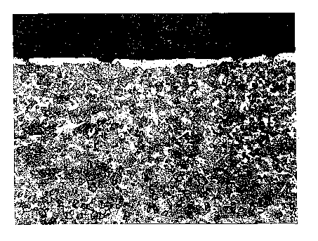
As shown in FIG. 5 and FIG. 6, the
microstructure of the as-sintered cutting insert
substrate exhibited a zone of essentially non-
stratified binder enrichment beginning at and extending
inwardly from a peripheral surface of the substrate for
a distance of about thirty micrometers. In this
regard, most all of the enrichment is of the non-
stratified type of binder enrichment and there is a
slight amount of the stratified type of binder
enrichment. Referring to the cobalt profile of FIG. 5,
the maximum level of cobalt concentration in the zone
of binder enrichment was between about 200 percent and
about 250 percent of the cobalt concentration of the
bulk substrate.. Referring to the photomicrograph of
FIG. 5, the porosity rating for the zone of binder
enrichment was C00. The porosity rating for the bulk
substrate was C02.
As shown in FIG. 8, the microstructure at the
corner of an as-sintered cutting insert substrate made
according to the step of Example 1 exhibited a zone of
essentially non-stratified binder (i.e., cobalt)
enrichment beginning at and extending inwardly from the
corner of the substrate a distance of about 20
micrometers. Even though the specific substrate shown
in FIG. 8 is not the exact same substrate represented
by FIGS. 5 and 6, applicants expect that the maximum
level of cobalt concentration in the zone of binder
enrichment should be between about 200 percent and 250
percent of the bulk cobalt content.
Example No. 1A
A powder mixture of the same composition as
Example No. 1 was prepared, pressed and processed in
the same way as Example No. 1, except that during the
controlled cooling step the nitrogen partial pressure
was at 70 torr. An analysis showed that there was a
zone of essentially non-stratified binder enrichment
beginning at the peripheral surface of the substrate
CA 02404294 2002-09-23
WO 01/73146 PCT/USO1/08933
-30-
and extending inwardly to a depth of about twenty-nine
micrometers. The apparent porosity of the zone of
binder enrichment was C00 and of the bulk substrate was
C02.
~ Example No. 2
For Example No. 2, green cutting insert
blanks were pressed from the same powder mixture as
Example No. 1 into SNG432 style green cutting insert
blanks. The processing steps were the same as those
used to process Example No. 1, except that the sinter
hold step had a duration of about forty-five minutes.
The depth of the zone of essentially non-stratified
binder enrichment was about twenty-three micrometers
and the maximum level of cobalt concentration in the
zone of binder enrichment was between about 200 percent
and about 250 percent of the cobalt concentration of
the bulk substrate. The porosity rating for the zone
of binder enrichment was C00 and the bulk substrate was
C02.
Example No. 2A
A powder mixture the same as the powder
mixture of Example No. 2 was prepared and processed in
the same way as Example No. 2, except that the
controlled cooling step was done at a nitrogen partial
pressure of 70 torr. There was a zone of essentially
non-stratified binder enrichment beginning at and
extending inwardly from the surface of the substrate to
a depth of about twenty-three micrometers. The
apparent porosity of the zone of the binder enrichment
was C00 and of the bulk substrate was C02.
Example Nos. 3, 3A and 3B
For Example Nos. 3, 3A and 3B the green
cutting insert blanks were pressed from a powder
mixture like the powder mixture of Example No.'1. The
green cutting insert blanks were processed like the
process of Example No. 1, except that the nitrogen
atmosphere was kept at 70 torr during the sinter heat
CA 02404294 2002-09-23
WO 01/73146 PCT/USO1/08933
-31-
step, the sinter hold step, and the controlled cool
down step. For Examples 3, 3A and 3B, each one of
these as-sintered cutting insert substrates had a zone
of essentially non-stratified binder enrichment that
began at and extended inwardly from the peripheral
surface toward the bulk substrate to a depth) of about
10, 10 and 10.4 micrometers, respectively. For each
one of the substrates the porosity rating for the zone
of binder enrichment was C00 and for the bulk substrate
was C02.
Examples Nos. 3C and 3D
A powder mixture of the same composition as
Example No. 3 was prepared and processed the same as
Example No. 3, except that the controlled cooling rate
was 11.1 degrees Centigrade per minute. Examples Nos.
3C and 3D exhibited a zone of binder enrichment that
began at and extended inwardly form the peripheral
surface to a depth of ten micrometers and thirteen
micrometers, respectively. For each example the
apparent of the zone of binder enrichment was C00 and
the porosity of the bulk substrate was C02.
Example' No . 6.
For Example No. 6, the same powder mixture as
Example 1 was processed in the~same way as Example 1 to
achieve an as-sintered cutting insert substrate. The
as-sintered cutting insert substrate was ground so that
the rake surface and the flank surfaces presented as-
ground surfaces. The ground as-sintered cutting insert
blanks were resintered in vacuum at a temperature of
1483 degrees Centigrade for a duration of about forty-
five minutes.
The resultant product was a resintered ground
cutting insert substrate with ground surfaces. The
resintered ground cutting insert substrate has a zone
of essentially non-stratified binder enrichment that
began at and extended inwardly from the periphery of
the ground surface for a depth of about thirty
CA 02404294 2002-09-23
WO 01/73146 PCT/USO1/08933
-32-
micrometers. The maximum level of cobalt concentration
in the zone of binder enrichment was between about 200
percent and about 250 percent. Referring to FIG. 7,
the photomicrograph shows that the porosity rating for
the zone of binder enrichment was C00 and for the bulk
substrate was C02.
Example 1057A through Example 1059C
Additional Examples 1057A-C, Examples 1058A-
C, and Examples 1059A-C were prepared with the starting
powder like Example 1 wherein the carbon levels for
Examples 1057A-C, 1058A-C and 1059A-C were 6.24, 6.21,
and 6.18 weight percent, respectively.
For Examples 1057A, 10578, 1058A, 10588,
1059A, and 10598, the processing comprised the
following steps: dewaxing step of heating at a rate of
2.78 degrees Centigrade per minute to 450 degrees
Centigrade in an atmosphere having a hydrogen positive
pressure; sinter heating from 450 to 1483 degrees
Centigrade in an atmosphere having either a 15 torr
nitrogen partial pressure (for Examples 1057-59A) or a
70 torr nitrogen partial pressure (for Examples 1057-
598); sinter holding for 45 minutes at 1483 degrees
Centigrade in an atmosphere having a 15 torr nitrogen
partial pressured controlled cooling at a rate of 11.1
degrees Centigrade per minute from 1483 to 1149 degrees
Centigrade in an atmosphere having a 15 torr nitrogen
partial pressure; and furnace cooling to ambient
temperature. The processing was the same, except that
Examples 1057-59A performed the sinter heat step in an
atmosphere with a 15 torr nitrogen partial pressure and
Examples 1057-598 were performed in an atmosphere with
a 70 torr nitrogen partial pressure. Each one of
Examples 1057A-10598 had a core porosity of C00.
Table I below sets forth the depth (in micrometers)
from the surface of the zone of non-stratified binder
enrichment.
CA 02404294 2002-09-23
WO 01/73146 PCT/USO1/08933
-33-
Table I
Depth of Zone of Binder Enrichment for Examples 1057A
through 1059B
Example 1057A 1058A 1059A 1057B 1058B 1059B
Depth 15 16 15 22 24 23
Table I shows that when the sinter heat step was
performed in an atmosphere with a higher nitrogen
partial pressure (70 torr vs. 15 torr) there was an
increase in the average depth of the zone of binder
enrichment (23 micrometers vs. 15.7 micrometers).
Examples 1057C, 1058C and 1059C were
processed in the same way as Examples 1057B through
1059B, except that the dewaxing occurred in an
atmosphere with a hydrogen partial pressure and the
controlled cooling step occurred at a rate of 0.94
degrees Centigrade per minute. Table II below presents
the depth of binder enrichment in micrometers and the
porosity of the bulk substrate. The results in Table
II show that while these differences in these
parameters did not change the depth of binder
enrichment, they did result in the stabilization of the
bulk substrate with C-type porosity that formed during
the dewaxing step under the hydrogen partial pressure.
Table II
Porosity and Depth of Enrichment for Examples 1057B-
1059C
Example 1057B 1058B 1059B 1057C 1058C 1059C
Depth 22 24 23 24 22 23
of
Enrichment
(~)
Core C00 C00 C00 C04 C02 C02
Porosity
CA 02404294 2002-09-23
WO 01/73146 PCT/USO1/08933
-34-
Examples TC1198 through TC 1211
Six additional examples (TC1209, TC1211,
TC1205, TC1207, TC1198 and TC1200) of cutting inserts
were made and performance tested against commercial
cutting inserts. For each one of the examples, the
starting powders were the same as Example 1 wherein the
carbon levels were adjusted as set forth in Table III
below.
Table III
Compositional and Performance Properties of Examples
TC1198-TC1211
Example/TC1209 TC1211 TC1205 TC1207 TC1198 TC1200
Component
Carbon 6.0579 6.0766 6.0954 6.1142 6.1330 6.1517
Content
(wt.~)
Core C00 C00 C02 C02 C02 C04
Porosity
Depth 31 31 29 30 33 32
of
Enrichment
(Dm)
Avg. 306 339 412 434 492 545
Tool
Life
(450
sfm)
Avg. 484 468 485 381 569 526
Tool
Life
(750
sfm)
The above powder mixtures were pressed into green
cutting insert blanks that were of a CNMG432-MG style
cutting inserts. The green cutting insert blanks had a
partial density of about fifty-five percent and had
open porosity.
All of the green compacts were processed
according to the following steps: (1) a two part
dewaxing step that comprised: (a) heating from 18
degrees Centigrade to 400 degrees Centigrade at a rate
CA 02404294 2002-09-23
WO 01/73146 PCT/USO1/08933
-35-
of 2.78 degrees Centigrade per minute under a hydrogen
partial pressure of hydrogen and holding at 400 degrees
Centigrade for one hundred twenty minutes, and (b)
heating from 400 degrees Centigrade 510 degrees
Centigrade at a rate of 2.78 degrees Centigrade per
minute under a hydrogen partial. pressure and holding
for one hundred twenty minutes (2) a sinter heat step
that comprised heating from 510 degrees Centigrade to
1470 degrees Centigrade at a rate of 2.78 degrees
10, Centigrade per minute under a nitrogen partial pressure
of 70 torr; (3) a sinter hold step at 1470 degrees
Centigrade for ninety minutes under a nitrogen partial
pressure of 15 torr; (4) a controlled cooling step from
1470 degrees Centigrade to 1150 degrees Centigrade at a
rate of 0.94 degrees Centigrade per minute under a
nitrogen partial pressure of 15 torr; and (5) furnace
cooling from 1150 degrees Centigrade to 38 degrees
Centigrade under a helium partial pressure; and (6)
coating via CVD the substrates so as to have an inner
layer of titanium carbonitride that was 4.5 micrometers
thick, a mediate layer of alumina that was 8.5
micrometers thick, and an outer layer of titanium
carbonitride/titanium nitride that was 1.5 micrometers
thick. Table III above sets forth the thickness of the
zone of binder enrichment in micrometers from a
peripheral flat surface of the substrate as determined
from a visual observation, and the porosity of the bulk
substrate, i.e., core porosity.
Table IV above sets forth the results of
slotted steel bar testing for the Examples set out
therein. Table IV presents the average tool life in
minutes for a slotted steel bar turning test performed
according to a first set of parameters, and the average
tool life in minutes for a slotted steel (AISI 41L50)
bar turning test performed according to a second set of
parameters. The first test parameters comprise a speed
of 450 surface feet per minute. The feed was started
CA 02404294 2002-09-23
WO 01/73146 PCT/USO1/08933
-36-
at .015 inches per revolution (ipr) and was increased
to .050 ipr in increments of .005 inches per 100
impacts. The depth of cut was .100 inches. The
turning was dry. The second test parameters comprise a
speed of 750 surface feet per minute. The feed started
at .015 inches per revolution (ipr) and was increased
to .050 ipr in increments of .005 ipr per 100 impacts.
The depth of cut was .100 inches. The turning was dry.
Table IV also sets forth the performance
results for the two commercial grades identified for
the purposes of these tests as KMT A and KMT B. For the
KMT A cutting insert, the substrate exhibited a zone of
non-stratified cobalt (binder) enrichment of a depth of
about twenty-five micrometers with a maximum cobalt
content of about two hundred percent of the bulk cobalt
content, and had a bulk porosity of A00-B00-C00. The
coating scheme for the KMT A cutting insert comprised:
a base layer of titanium carbonitride that was about
two micrometers thick, an intermediate layer of
titanium carbide that was about four micrometers thick,
and an outer layer of alumina that was about 1.5
micrometers thick wherein all three layers were applied
by CVD techniques.
For the KMT B cutting insert, the substrate
exhibited a zone of stratified binder enrichment of a
depth of twenty micrometers with a maximum cobalt
content of about three hundred percent of the bulk
content, and had a bulk porosity of C04 to C06. The
coating scheme for the KMT B cutting insert comprised:
a base layer of titanium carbide that was 4.5
micrometers thick, an intermediate layer of titanium
carbonitride that was 3.5 micrometers thick, and an
outer layer of titanium nitride that was 3 micrometers
thick wherein all of the layers were applied by CVD
techniques.
Table IV below sets forth the tool life and
failure mode for Examples TC1209, TC1211, TC1205,
CA 02404294 2002-09-23
WO 01/73146 PCT/USO1/08933
-37-
TC1207, TC1198, and TC1200. Table IV presents the bulk
substrate porosity, the results in minutes and tool
life criteria for each of three separate runs, and the
average tool life in minutes. The turning test was
performed on a AISI 4340 steel workpiece at a speed of
500 surface feet per minute, a feed of .014 inches per
revolution, a depth of cut of .100 inches, and turning
was done dry, i.e., no coolant. Tool life criteria
comprised flank wear (fw) of .015 inches: maximum flank
wear (mfw) of .030 inches; nose wear (nw) of .030
inches depth of cut notch (dn) of .030 inches and
crater wear depth (cr) of .004 inches.
Table IV - Test Results from Turning Test on AISI 4340
Steel Workpiece
Example Bulk Run 1 Run 2 Run 3 Tool Life
Porosity (minutes)(minutes) (minutes)Average
(minutes)
TC1209 C00 36.1 nw-cr35.0 nw 31.8 nw 34.3
TC1211 C00 35.6 fn-nw30.6 nw 30.9 nw 32.4
TC1205 C02 35.0 nw 31.0 nw 30.1 nw 32.0
TC1207 C02 37.7 nw 36.1 nw 30.5 nw 34.8
TC1198 C04 29.4 nw 32.2 mw 30.2 nw 30.6
TC1200 C06 30.1 nw-cr30.2 nw 25.8 nw 28.7
KMT A AOOlB00 19.4 cr 20.3 nw 20.1 nw 19.9
KMT B C08 Min 17.7 cr 16.4 nw 18.0 nw 17.4
Examples TC1247A through TC1247C
Additional Examplls TC1247A through TC1247C,
TC1248A through TC1248C, and TC1249A through TC1249C
were prepared wherein the starting powder mixture
CA 02404294 2002-09-23
WO 01/73146 PCT/USO1/08933
-38-
contained the following components (in weight percent):
6.0 cobalt, 2.59 tantalum, 2.00 titanium, 0.91 niobium,
and the balance tungsten and carbon wherein the carbon
levels were adjusted so that Examples TC1247A-C,
TC1248A-C and TC1249A-C had carbon levels of 6.15, 6.10
and 6.07 weight percent, respectively. The starting
powder mixture contained .63 weight percent titanium
nitride, which contributed 0.5 weight percent of the
titanium content, so that an effective amount of
nitrogen was in the starting powder mixture for these
examples.
The processing of these examples comprised
the steps of: a two-stage dewaxing step in a hydrogen
partial pressure comprising heating at a ramp rate of
5.36 degrees Centigrade per minute from ambient
temperature to 400 degrees Centigrade, then holding for
30 minutes, then heating from 400 to 510 degrees
Centigrade at a ramp rate of 5.36 degrees Centigrade,
and then holding for 15 minutes a sinter heating step
of heating from 510 to 1468 degrees Centigrade in an
atmosphere with a nitrogen partial pressure of 70 torr;
a sinter hold step of holding at 1468 degrees
Centigrade under an atmosphere having a nitrogen
partial pressure of either 15 torr (Examples TC1247A,
TC1248A and TC1249A), 45 torr (Examples TC1247B,
TC1248B, and TC1249B) or 70 torr (Examples TC1247C,
TC1248C and TC1249C); a controlled cooling step of
cooling at a rate of 0.94 degrees Centigrade per minute
from 1468 to 1149 degrees Centigrade (a temperature
below the eutectic temperature) under an atmosphere
having a nitrogen partial pressure of either 15 torr
(Examples TC1247A, TC1248A and TC1249A), 45 torr
(Examples TC1247B, TC1248B and TC1249B) or 70 torr
(Examples TC1247C, TC1248C, and TC1249C)~ and a furnace
cooling step under a helium atmosphere of cooling from
1149 degrees Centigrade to ambient temperature.
CA 02404294 2002-09-23
WO 01/73146 PCT/USO1/08933
-39-
Table V below sets forth the carbon content
in weight percent of the starting powder mixture, the
nitrogen partial pressure (in torr) in the sinter
holding step, the depth of the zone of binder
enrichment in micrometers, and the porosity of the bulk
substrate for Examples TC1247, TC1248 and TC1249.
Table V
Properties of Examples TC1247-49
Example/' Starting Depth of Zone of Core Porosity
Carbon Content/NitrogenBinder
Partial Pressure Enrichment (Nm)
in
Sinter Hold Step
TC1247A/6.15/ 15 57 A04-B00-C06
torr
TC1247B/6.15/ 45 46 A04-B00-1-C06
torr
TC1247C/6.15/ 70 39 A04-B00-C06
torr
TC1248A/6.10/ 15 54 A02-B00-C05
torr
TC1248B/6.10/ 45 43 A02-B00-1-C04
torr
TC1248C/6.10/ 70 32 A02-B00-C05
torr
TC1249A/6.07/ 15 49 A02-B00-1-C02
torr
TC1249B/6.07/ 45 35 A02-B00-1-C02
torr
TC1249C/6.07/ 70 28 A02-B00-1-C02
torr
A review of the above results shows that for a starting
powder mixture that contains some nitrogen, the greater
the nitrogen partial pressure during the sinter hold
step results in a decrease in the depth of the zone of
binder enrichment. These results also show that the
porosity of the bulk substrate remains generally
consistent even though the sinter hold step occurred at
different nitrogen partial pressures. Finally, these
results show that the carbon level of the starting
CA 02404294 2002-09-23
WO 01/73146 PCT/USO1/08933
-40-
powder mixture impacts upon the depth of the zone of
binder enrichment.
Examples TC1247D, TC1248D, TC1249D, which had
the same composition of the starting powder mixture as
Examples TC1247A, TC1248A, and TC1249A, respectively,
were processed according to the following steps (1) a
dewaxing step comprising heating in a hydrogen partial
pressure (e. g., 5 to 30 torr) from ambient temperature
to 593 degrees Centigrade and holding for 15 minutes
(2) sinter heating in a vacuum (75 microns or less)
from 593 to 1121 degrees Centigrade and holding for 10
minutes (3) sinter heating still in a vacuum froze 1121
to 1288 degrees Centigrade and holding for 10 minutes
(4) sinter heating under 15 torr argon atmosphere from
1288 to 1482 degrees Centigrade; (5) sinter holding in
a 15 torr argon atmosphere for 45 minutes at 1482
degrees Centigrade; and (6) cooling from 1482 degrees
Centigrade to 52 degrees Centigrade at a cooling rate
of 277 degrees Centigrade per minute. Table VI sets
forth the carbon level in weight percent in the
starting powder, the depth of zone of binder enrichment
in micrometers, and the bulk porosity.
Table VI
Properties of Examples 1247D-1249D
Example Carbon Zevel Depth of Zone Porosity
(wt.%) of Binder
Enrichment
(fun)
TC1247 6.15 18 A04-B00-(C08)
TC1248 6.10 16 A04-B00-1-C05
TC1249 6.07 16 A02-B00-2-C00
These results show that when the processing includes a
vacuum then the depth of the zone of binder enrichment
becomes less than when processed under an atmosphere
with a nitrogen partial pressure.
CA 02404294 2002-09-23
WO 01/73146 PCT/USO1/08933
-41-
A heat of 5821 cutting insert blanks of the
same composition, but of various geometries and sizes,
was run to determine the consistency of enrichment and
the porosity of the bulk substrate for blanks at
different locations in the heat. The composition of
the starting powder mixture contained the following
components: 6.00 weight percent cobalt, 2.61 weight
percent tantalum, 2.00 weight percent titanium, 0.88
weight percent niobium, and the balance tungsten and
carbon wherein the carbon level was adjusted to equal
to 6.13 weight percent. The process comprised steps to
make the substrate like those set for Examples TC1198-
TC1211.
A sampling of as-sintered cutting insert
substrates from various locations throughout the heat
showed that the depth of binder enrichment only varied
between twenty-three and twenty-six micrometers and the
porosity of the bulk substrate only varied between A00-
B00-C04 and A00-B00-C06. The consistency of these
properties for as-sintered cutting insert substrates
taken from various locations throughout the entire heat
was excellent.
For the above examples set forth in this
patent application the compositions of the starting
powder mixtures were expressed in terms of the weight
percent of the component elements. However, in
practice it would be typical that some of the elements
would be present in powders of compounds. For example,
a tungsten-titanium carbide powder would make a
contribution of tungsten, titanium and carbon to the
powder mixture, a tantalum-niobium carbide would make a
contribution of tantalum, niobium and carbon to the
powder mixture, and a cemented (cobalt) tungsten
carbide powder would make a contribution of tungsten,
cobalt and carbon to the powder mixture.
As mentioned hereinabove, applicants believe
that the presence of nitrogen in the bulk region of the
CA 02404294 2002-09-23
WO 01/73146 PCT/USO1/08933
-42-
substrate, as well as in the surface zone of binder
enrichment, should provide certain advantages.
Applicants do not intend to be limited by the following
explanation of one possible scientific theory that may
have application to a process that produces an as-
sintered cemented (cobalt) tungsten carbide substrate
with a surface zone of essentially non-stratified
cobalt enrichment and that applicants believe possesses
higher (or desirably high) levels of nitrogen in the
bulk region and in the zone of binder enrichment.
It is applicants' belief that to obtain a
higher level of nitrogen in the as-sintered substrate,
and especially in the~surface zone of binder
enrichment, a high nitrogen partial pressure should be
maintained during the sinter hold step. Such a higher
nitrogen partial pressure should prevent, or at least
limit, the evolution of nitrogen atoms from the binder
(e. g., cobalt).
The nitrogen activity in the cobalt binder of
a cemented (cobalt) tungsten carbide can be calculated
based upon the following equations:
'~N2 ( prr2 ) H N ( arr ) ( 1A )
OG = 0G° + RTlnK (2A)
wherein pN2 is the nitrogen partial pressure, K is the
chemical reaction rate constant, and G is the Gibb's
free energy. At equilibrium, when 0G=0, K is expressed
by the equation:
K=exp [-DG°/RT]=aN/ (pN2) 1/2 (3A)
At certain sintering temperatures (T), e.g.,
the temperature of the sinter hold step, the nitrogen
activity (aN) is determined by the nitrogen partial
pressure. In practice, an increase in the nitrogen
activity from al to a2 can be determined by an increase
in the nitrogen partial pressure from P1 to P2 per the
following equation:
P2/P1 = (a2/al)2 (4A)
CA 02404294 2002-09-23
WO 01/73146 PCT/USO1/08933
-43-
For example, at a constant temperature, to double the
nitrogen activity of a treatment, i.e., the a21a1 ratio
is equal to 2, at a nitrogen partial pressure of 15
torr, one would need to increase the nitrogen partial
pressure four-fold to 60 torr so as to satisfy equation
(4A) . .
Examples X207-1 through X207-3
For Examples X207-1 through X207-3, the
starting powder mixture contained the following
components: 6 weight percent cobalt, 2.7 weight percent
tantalum, 2.0 weight percent titanium, 0.8 weight
percent niobium and the balance of the starting powder
mixture was tungsten and carbon. In the starting
powder mixture, 2 weight percent of the titanium, i.e.,
about 100 percent of the titanium, came from titanium
nitride in the starting powder mixture so that the
starting powder mixture contained an effective amount
of nitrogen wherein the nitrogen assisted in the
formation of the zone of binder enrichment.
Five kilograms (kg) of the powder mixture
charge for Examples X207-1 through X207-3 were added to
a 7.5 inch (19.05 centimeters) inside diameter by 9
inch (22.9 centimeters) steel mill jar along with 21
kilograms of 5/l6th inch diameter cemented carbide
cycloids. Heptane was added to the top of the jar so
that the jar was completely full. The mixture was
rotated for forty hours at fifty-two revolutions per
minute (rpm) at ambient temperature. The slurry from
the charge was then emptied from the jar and dried,
paraffin added as a fugitive binder, and the powders
were granulated so as to provide for adequate flow
properties. These granulated powders were then pressed
into SNG433 style green cutting (turning) insert
blanks, i.e., a compacted mass of starting powders,
which exhibited partial density as well as open
porosity.
CA 02404294 2002-09-23
WO 01/73146 PCT/USO1/08933
-44-
The general process parameters for the
production of Examples X207-1 through X207-3 are set
forth hereinafter.
For all of the Examples X207-1 through X207-
3, the green cutting insert blanks were heated (or
dewaxed) under a partial pressure of hydrogen gas from
ambient temperature to about 510 degrees Centigrade
(950 degrees Fahrenheit) to form dewaxed cutting insert
blanks. During the dewaxing step, the fugitive binder
evaporated from the green cutting insert blanks. The
dewaxed cutting insert blanks were held at about 510
degrees Centigrade for ten minutes in a vacuum.
Following the vacuum-hold step there was a
sinter heating (or sinter heat) step in which flowing
nitrogen gas was introduced so that the atmosphere had
a nitrogen partial pressure (i.e., a sinter heat
nitrogen partial pressure [P1] in Table VII]) for the
entire time that the dewaxed cutting insert blanks were
heated at a rate of about 2.78 degrees Centigrade per
minute from about 510 degrees Centigrade to the maximum
sintering temperature of about 1468 degrees Centigrade.
These sinter heat nitrogen partial pressures (P1) were
different for the examples, and the specific nitrogen
partial pressures, are set forth in Table VII
hereinafter. The dewaxed cutting insert blanks were
transformed into pre-sintered cutting insert blanks.
A sinter holding step followed the sinter
heating step. At the start of the sinter holding step
the nitrogen partial pressure was increased, remained
the same or reduced to the sinter hold nitrogen partial
pressures(P2) as set forth in Table VII and the
temperature was maintained at about 1468 degrees
Centigrade (2675 degrees Fahrenheit) for a period of
about 90 minutes. The pre-sintered cutting insert
blanks were transformed into as-sintered cutting insert
blanks wherein these blanks exhibited substantially
full density.
CA 02404294 2002-09-23
WO 01/73146 PCT/USO1/08933
-45-
A controlled cooling step followed the sinter
holding step. In the controlled cooling step, the
nitrogen partial pressure remained at about 15 torr and
the as-sintered cutting insert blanks were cooled at a
rate of about 1.0 degrees Centigrade per minute (1.7
degrees Fahrenheit per minute) until reaching a
temperature of about 1150 degrees Centigrade (2100
degrees Fahrenheit) which was below the eutectic
temperature of about 1315 degrees Centigrade.
The next step was a furnace cooling step
under a helium partial pressure in which the as-
sintered cutting insert blanks were permitted to
furnace cool to ambient temperature 38 degrees
Centigrade. The resultant product of the above
processing steps was an as-sintered cutting insert
substrate.
In addition to the sinter heat nitrogen
partial pressure and the sinter hold nitrogen partial
pressure (both set forth in torr), Table VII sets forth
other properties including the porosity of the bulk
region of the substrate, the depth (in micrometers) of
the surface zone of binder enrichment, and the maximum
level of cobalt in the surface zone of binder
enrichment. The maximum level of cobalt in the surface
zone of binder enrichment is set forth as a percentage
of the cobalt content of the bulk region. The porosity
of the bulk region were determined according to ASTM
Designation B-276-91 (Reapproved 1996).
CA 02404294 2002-09-23
WO 01/73146 PCT/USO1/08933
-4 6-
Table VII
Selected Process Parameters and Properties
of Examples Nos. X207-1 through X207-3
Example/PropertyX207-1 X207-2 X207-3
Sinter Heat 15 torr 15 torr 70 torr
Nitrogen Partial
Pressure (P1]
Sinter Hold 70 torr 15 torr 15 torr
Nitrogen Partial
Pressure [P2]
Depth 2( ~ 42 Etm 65 ~m
(micrometers)
of
Zone of Binder
Enrichment
Maximum Cobaltabout 210 about 225 about 175
Content in
the
Surface Zone
of
Binder
Enrichment
Porosity of A02-B00-C00 A02-B00-C00 A02-B00-C03
the
Bulk Region
Referring to Examples X207-1 through X207-3,
it is apparent that the depth of the surface zone of
binder enrichment can be controlled by selecting the
sinter hold nitrogen partial pressure and/or the sinter
heat nitrogen partial pressure. Applicants note that
binder enrichment still occurs even in the case where
the sinter hold nitrogen partial pressure (P2) is over
four times as great as the sinter heating nitrogen
partial pressure (P1). For examples X207-1 through
X207-3, the nature of the binder enrichment in the
surface zone is essentially non-stratified binder
enrichment.
Examples 1059-4 through 1059-6
Examples 1059-4 through 1059-6 had a
composition the same as Example 1 hereof, except that
the carbon content was adjusted to equal 6.18 weight
percent. Examples 1059-4 through 1059-6 were processed
in a manner the same as Examples X207-1 through X207-3,
respectively. Table VIII sets out the nitrogen partial
CA 02404294 2002-09-23
WO 01/73146 PCT/USO1/08933
-47-
pressure for the sinter heating step (P1) and the
nitrogen partial pressure for the sinter holding step
(P2),' as well as other properties including the
porosity of the bulk region of the substrate, the depth
(in micrometers) of the surface zone of binder
enrichment, and the maximum cobalt content in the
surface zone of binder enrichment. The maximum cobalt
content in the surface zone of binder enrichment is set
forth is set forth as a percentage of the cobalt
content of the bulk region. The porosity of the bulk
region were determined according to ASTM Designation B-
276-91 (Reapproved 1996).
Table VIII
Selected Process Parameters and Properties
~ of Examples Nos. 1059-4 through 1059-6.
Example/PropertyEx. 1059-4 1059-5 1059-6
Sinter Heat 15 torr 15 torr 70 torr
Nitrogen Partial
Pressure [P1]
Sinter Hold 70 torr 1~5 torr 15 torr
Nitrogen Partial
Pressure [P2J
Depth None 16 ~.m 22 Eun
(micrometers)
of
Zone of Binder
Enrichment
Degree of Not applicableabout 180 about 210
Enrichment
in
the Zone of
Binder
Enrichment
Porosity of A02-B00-C00 A02-B00-C00 A02-B00-C02
the
Bulk Region
Referring to Examples 1059-4 through 1059-6,
these examples show that the depth of the zone of
cobalt enrichment may be controlled (i.e., varied in a
predictable fashion) by adjusting the nitrogen partial
pressure in the sinter heating step and/or the sinter
holding step. Furthermore, these Examples 1059-4
through 1059-6 demonstrate that as-sintered substrates
CA 02404294 2002-09-23
WO 01/73146 PCT/USO1/08933
-48-
that exhibit either a surface zone of binder enrichment
at least 5 micrometers deep or an absence of a surface
zone of binder enrichment can be made from a starting
powder with the same composition. Such a feature of
the process permits one to only store or make one
starting powder mixture to produce two different as-
sintered substrates wherein one of the as-sintered
substrates has a surface zone of binder enrichment and
the other as-sintered substrate does not exhibit a
surface~zone of binder enrichment.
Examples from Heat 1723 and Heat 1660
The six examples from Heat 1723 are
identified in Table IX below. These examples from Heat
1723 were processed in a fashion like Example 1 hereof,
except that the nitrogen partial pressure during the
sinter heating step was 70 torr, the nitrogen partial
pressure during the sinter hold step was 15 torr, and
the ramp rate for the heating step was 1.11 degrees
Centigrade per minute (2 degrees Fahrenheit per
minute). The composition of the examples from Heat
1723 were the same as Example 1 hereof, except that the
carbon level for each example was adjusted to the
values as set forth in Table IX. Examples TC1206/RH-
1723 and TC1199/RH-1723 comprised as-sintered
substrates that had at least one surface ground prior
to the sintering process. The properties pertaining to
the zone of binder enrichment were determined from the
ground surface.
Table IX below sets forth the depth of cobalt
enrichment in micrometers, the porosity of the bulk
region of the substrate was determined according to
ASTM Designation B276-91 (Reapproved 1996), the
magnetic saturation value (gauss~cm3 per gram), the
coercive force (H~) in oersteds, and the density of the
material in grams per cubic centimeter.
CA 02404294 2002-09-23
WO 01/73146 PCT/USO1/08933
-49-
Table IX
Properties of Examples from Heat 1723
[P1 = 70 torr; P2 = 15 torr; sinter heat ramp rate =
1.11 degrees Centigrade per minute]
Example/ Depth of Porosity MS H~ Density
[wt% Cobalt (gausscm3(Oersteds)(g/cm3)
carbon] Enrichment per gram)
(0m )
TC1205- 40 A02-COO-1-9.5 157 14.01
1723 C01
[6.0954%]
TC1207- 43 A02-B00- 9.4 162 14.01
1723 C02
[6.1142%]
TC1198- 40 A02-B00-1-9.6 151 13.99
1723 C03
[6.1330%]
TC1200- 40 A02-B00- 9.6 149 13.98
1723 (C03)C05
[6.1517%]
TC12061RH-45 A02-B00- 9.5 147 13.99
1723 C03
TC1199/RH-43 A02-B00- 9.5 151 13.98
1723 C05
The six examples from Heat 1660 were
processed like the Examples from Heat 1723, except that
the ramp rate for the sinter heating step was at a
faster rate of 2.78 degrees Fahrenheit (5 degrees
Centigrade) per minute. Examples TC1206/RH-1660 and
TC1199/RH-1660 comprised as-sintered substrates that
had at least one surface ground prior to the sintering
process. The properties pertaining to the zone of
binder enrichment were determined from the ground
surface. Table X below sets forth the depth of cobalt
enrichment in micrometers, the porosity of the bulk
region of the substrate according to ASTM Designation
B276-91 (Reapproved 1996), the magnetic saturation
value (gauss~cm3 per gram), the coercive force (HC) in
CA 02404294 2002-09-23
WO 01/73146 PCT/USO1/08933
-50-
'r
oersteds, and the density of the material in grams per
cubic centimeter.
Table X
Properties of Examples from Heat 1660
Example/ Depth of Porosity MS H~ Densit~r
[wt% Cobalt (gausscm3 (Oersteds)(g/cm )
carbon] Enrichment per gram)
(gym)
TC1205- 29 C00 9.5 159 14.00
1660
[6.0954%]
TC1207- 30 (C02)C03 9.5 158 14.00
1660
[6.1142%]
TC1198- 33 (C03)C05 9.7 153 13.98
1660
[6.1330%]
TC1200- 32 (C05)C06 9.7 150 13.96
1660
[6.1517%]
TC1206/RH-32 C02 9.4 165 14.01
1660
TC1199/RH-33 C05 9.6 158 13.98
1660
Referring to the examples from Heat 1723 and Heat 1660,
it becomes apparent that the ramp rate during the
sinter heating step impacts upon the depth of binder
enrichment when the sinter heating step occurs in a
nitrogen partial pressure. For all of the examples,
the depth of the cobalt enrichment increased with the
slower ramp rate (1.11 degrees Centigrade per minute
vs. 2.78 degrees Centigrade per minute) during the
sinter heating step.
l5 Examples from Heat 1724
The six examples from Heat 1724 were
processed in a fashion like the examples from Heat
1660, except that the nitrogen partial pressure during
the sinter hold step was 1.5 torr. Examples
CA 02404294 2002-09-23
WO 01/73146 PCT/USO1/08933
-51-
TC1206/RH-1724 and TC1199/RH-1724 comprised as-sintered
substrates that had at least one surface ground prior
to the sintering process. The properties pertaining to
the zone of binder enrichment were determined from the
ground surface. Table XI below sets forth the depth of
cobalt enrichment in micrometers, the porosity of the
bulk substrate according to ASTM Designation B276-91
(Reapproved 1996), the magnetic saturation value
(gauss~cm3 per gram), the coercive force (H~) in
oersteds, and the density of the material in grams per
cubic centimeter.
Table XI
Properties of Examples from Heat 1724
Example/ Depth of Porosity MS H~ . Density
[wt% Cobalt (gausscm3 (Oersteds)(g/cm3)
carbon] Enrichment per gram)
(gym)
TC1205- 43 A02-B00-CO9.2 156 14.04
1724
[6.0954%
TC1207- 43 A02-C00- 8.9 162 14.05
1724 C00
[6.1942%]
TC1198- 39 A02-B00-1-9.0 155 14.02
1724 (C02)C03
[6.1330%]
TC1200- 43 A02-B00- 9.2 150 14.00
1724 C03
[6.1517%]
TC1206/RH-57 A02-B00- 8.9 148 14.03
1724 C03
TC1199/RH-60 A02-B00-1-8.9 151 14.02
1724 C03(C05)
A comparison of the examples from Heat 1724 to the
Examples from Heat 1660 shows that the depth of the
zone of binder enrichment can be increased with a
decrease in the nitrogen partial pressure during the
sinter hold step.
CA 02404294 2002-09-23
WO 01/73146 PCT/USO1/08933
-52-
Overall, it is apparent that applicants have
invented a new and useful process for the production of
a cutting insert, as well as the cutting insert itself.
By making a calculation of the equilibrium nitrogen
partial pressure at various temperatures, applicants
can control the depth of the zone of binder enrichment
that forms in a cemented carbide as-sintered cutting
insert substrate. Applicants can also avoid the
precipitation of carbon in the zone of binder
enrichment through the use of a controlled cooling
step. Applicants can also provide for a cutting insert
substrate with a consistent bulk porosity.
By calculating the nitrogen activity in the
sinter heating step and the sinter holding step,
applicants can control the depth of the zone of binder
enrichment. Applicants further believe that one can
control (e.g., increase) the nitrogen content in as-
sintered substrate including in the bulk region and the
zone of binder enrichment. An as-sintered substrate
that has a desirably high nitrogen content has nitrogen
atoms present at the interstices of the cobalt atoms
that should facilitate solid-solution hardening,
especially for a substrate that with the bulk region
that exhibits a porosity of greater than C00 according
to ASTM Designation B276-91 (Reapproved 1996).
It is believed that an as-sintered substrate
that has bulk region with a porosity of not greater
than C00 according to ASTM Designation B276-91
(Reapproved 1996) and a zone of binder enrichment with
a desirably high nitrogen content helps promote the
nucleation of titanium nitride during the application
of titanium nitride as the layer on the surface of the
substrate. An as-sintered substrate that has bulk
region with a porosity of greater than C00 according to
ASTM Designation B276-91 (Reapproved 1996) and a zone
of binder enrichment with a desirably high nitrogen
content should help promote the nucleation of titanium
CA 02404294 2002-09-23
WO 01/73146 PCT/USO1/08933
-53-
carbonitride during the application of titanium
carbonitride as the layer on the surface of the
substrate.
It is believed that by providing additional
nitrogen in the cobalt binder there should be an
increase in the chemical affinity between the substrate
and the nitrogen-containing coating, such as, for
example, titanium nitride or titanium carbonitride. An
increase in the availability of nitrogen in the cobalt
near the surface of the substrate should reduce the
potential for the formation of a brittle eta phase at
the interface between the coating and the substrate.
It is believed that a higher nitrogen content
in the substrate also should result in a decrease in
the grains size of the tungsten carbide. An increase
in the N/(C+N) content should lead to a decrease in the
grain size of the tungsten carbide. The tungsten
carbide phase content in the microstructure should
increase to a maximum as the N/(C+N) ratio increases.
All patents, patent applications, articles
and other documents identified herein are hereby
incorporated by reference herein.
Other embodiments of the invention may be
apparent to those skilled in the art from a
consideration of the specification or the practice of
the invention disclosed herein. It is intended that
the specification and any examples set forth herein be
considered as illustrative only, with the true spirit
and scope of the invention being indicated by the
following claims.