Language selection

Search

Patent 2404718 Summary

Third-party information liability

Some of the information on this Web page has been provided by external sources. The Government of Canada is not responsible for the accuracy, reliability or currency of the information supplied by external sources. Users wishing to rely upon this information should consult directly with the source of the information. Content provided by external sources is not subject to official languages, privacy and accessibility requirements.

Claims and Abstract availability

Any discrepancies in the text and image of the Claims and Abstract are due to differing posting times. Text of the Claims and Abstract are posted:

  • At the time the application is open to public inspection;
  • At the time of issue of the patent (grant).
(12) Patent: (11) CA 2404718
(54) English Title: INTEGRATED TRAIN LOCATION SYSTEM
(54) French Title: SYSTEME INTEGRE DE LOCALISATION DE TRAIN
Status: Expired and beyond the Period of Reversal
Bibliographic Data
(51) International Patent Classification (IPC):
  • B61L 25/00 (2006.01)
  • B61L 25/02 (2006.01)
(72) Inventors :
  • MCALLISTER, LAWRENCE LAWSON (United Kingdom)
(73) Owners :
  • SIEMENS RAIL AUTOMATION HOLDINGS LIMITED
(71) Applicants :
  • SIEMENS RAIL AUTOMATION HOLDINGS LIMITED (United Kingdom)
(74) Agent: SMART & BIGGAR LP
(74) Associate agent:
(45) Issued: 2011-03-01
(22) Filed Date: 2002-09-23
(41) Open to Public Inspection: 2003-03-25
Examination requested: 2007-02-02
Availability of licence: N/A
Dedicated to the Public: N/A
(25) Language of filing: English

Patent Cooperation Treaty (PCT): No

(30) Application Priority Data:
Application No. Country/Territory Date
0123058.0 (United Kingdom) 2001-09-25

Abstracts

English Abstract


A train location arrangement is disclosed that interleaves a plurality of
detection systems to
provide, in combination, a higher resolution of train detection than would be
provided by one of
the systems on its own.


French Abstract

L'invention décrite dans la présente divulgation a trait à un dispositif de localisation de trains qui entrelace une pluralité de systèmes de détection conçus pour assurer un degré de détection des trains supérieur à ce qui pourrait être obtenu par un seul système.

Claims

Note: Claims are shown in the official language in which they were submitted.

CLAIMS
1. A train location arrangement comprising at least a first train detection
means and a
second train detection means; said first train detection means comprising a
plurality
of track circuits; said second train detection means comprising a plurality of
axle
counters; each of said plurality of track circuits and each of said plurality
of axle
counters being in sections, and interleaved such that each track circuit
section is
offset from each axle counter section; wherein the location of a train may be
determined to be within a length of track smaller than the length of either a
track
circuit section or an axle counter section by combining detection signals from
both
the first train detection means and the second train detection means.
2. A train location arrangement according to claim 1, wherein train detection
information from the two detection means is combined in order to provide for
improved availability, so that if one of the detection means fails, then train
location
is still provided.
3. A train location arrangement according to claim 1, wherein train detection
information from the two detection means is combined in order to provide for
improved safety, so that if one of detection means fails to correctly indicate
the location
of a train, then safe detection is still provided.
4. A train location arrangement according to claim 1, wherein one of the train
detection
means is a track circuit and another is an axle counter and wherein if the
axle
counters indicate that a track circuit section is clear, this is utilized to
enable auto-
adjustment of the track circuit section.
5. A train location arrangement according to claim 1, wherein if an axle
counter
indicates that a track circuit section is clear, this is utilized to change
the indication
of the track circuit in the 1st section.
6. A train location arrangement utilizing a plurality of train detection
systems which are
interleaved to provide, in combination, a higher resolution of train detection
than
would be achieved by one of the systems on its own comprising at least a first
train

detection means and a second train detection means; each of said train
detection
means being in sections and interleaved such that each of the sections of the
first
train detection means are offset from each of the sections of the second train
detection means; wherein the location of a train may be determined to be
within a
length of track smaller than the length of either a first train detection
means sections
or a second train detection means section by combining detection signals from
both
the first train detection means and the second train detection means.
7. A train location arrangement comprising at least a first train detection
means and a
second train detection means; said first train detection means comprising a
plurality
of track circuits; said second train detection means comprising a plurality of
axle
counters; each of said plurality of track circuits and each of said plurality
of axle
counters being interleaved and in sections, said axle counter in a first
section
indicating a first condition in the absence of a passing train in the first
section and
second condition in the presence of a passing train in the first section; said
track
circuit indicating the presence or absence of a train in the first section;
said axle
counter in the first section changing from said second condition to said first
condition on the indication of the absence of a train by said track circuit in
the first
section.
8. A train location means comprising at least a first train detection means
and a
second train detection means; said first train detection means comprising a
plurality
of track circuits; said second train detection means comprising a plurality of
axle
counters; each of said plurality of track circuits and each of said plurality
of axle
counters being interleaved and in sections, said track circuits in a first
section
indicating a first condition in the absence of a passing train in the first
section and
second condition in the presence of a passing train in the first section; said
axle
counter indicating the presence or absence of a train in the first section;
said track
circuit in the first section changing from said second condition to said first
condition
on the indication of the absence of a train by said axle counter in the first
section.

Description

Note: Descriptions are shown in the official language in which they were submitted.


CA 02404718 2010-10-20
1
INTEGRATED TRAIN LOCATION SYSTEM
The present invention relates to train detection.
Train detection is a key part of a railway control system and the availability
of accurate
information about train location is essential to the safe and smooth running
of a railway.
Traditionally, either track circuits or axle counter techniques have been used
to provide train
detection and there are various advantages and disadvantages associated with
the selection of
either axle counter or track circuit systems. Some of the trade-offs are:
= Track circuits offer continuous detection of trains along the circuit length
while axle counters
only detect the passage of vehicles at points.
= Track circuits offer the potential for emergency protection by shunting the
rails, unlike axle
counters.
= Axle counters are significantly more isolated from the rail and thus perform
better in the
presence of electric traction.
= Track circuits generally complicate electrical traction return bonding.
= Track circuits offer some degree of rail continuity detection, unlike axle
counters.
= Axle counters need to be initialized at power up while track circuits can
readily determine if
the track is clear when initially powered up.
= Short track circuits require physical rail isolating joints which are
expensive to install and
maintain.
= Track circuits are vulnerable to severe rail contamination which makes
reliable train detection
in all seasons difficult.
A system that utilizes both axle counters and track circuits could draw from
the best features of
both. However, to just lay the two systems on top of each other is
unjustifiably expensive, so
such an approach would be immediately rejected.
According to the present invention, there is provided a train location
arrangement utilizing a
plurality of train detection systems which are interleaved to provide, in
combination, a higher
resolution of train detection than would be achieved by one of the systems on
its own.

CA 02404718 2002-09-23
2
Train detection information from the systems could be combined in order to
provide for
improved availability, so that if one of the systems fails, then train
location is still provided by
the or each other system.
Train detection information from the two systems could be combined in order to
provide for
improved safety, so that if one of systems fails to correctly indicate the
location of a train, then
safe detection is still provided by the or each other system.
Preferably, the train detection systems are different from each other.
One of the train detection systems could be a track circuit system.
One of the train detection systems could be an axle counter system.
If one of the systems is a track circuit system and the other or another of
the systems is an axle
counter system, the arrangement could be such that if a track circuit section
indicates that an axle
counter section is clear, this enables a reset of the axle counter section.
If one of the systems is a track circuit system and the other or another of
the systems is an axle
counter system, the arrangement could be such that if axle counters indicate
that a track circuit
section is clear, this is utilized to enable auto-adjustment of the track
circuit section.
The present invention will now be described, by way of example, with reference
to the
accompanying drawings, in which:-
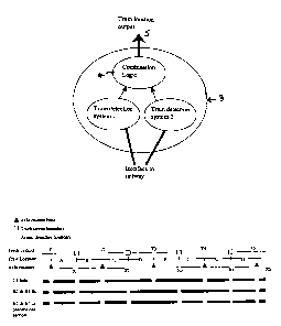
Fig. I is a schematic outline of an example of an arrangement according to the
present invention;
Fig. 2 shows interleaving of track circuit and axle counter sections;
Fig. 3 shows a basic "AND" combination logic which may be used; and
Fig. 4 shows a more advanced combination logic with an override facility.
Referring first to Fig. 1, the outputs from two different (diverse) train
detection systems 1 and
2 in a train location arrangement 3 and interfaced to a railway are combined
in combination logic

CA 02404718 2002-09-23
3
4 to provide a train location output at 5. In the following example, one of
the systems is a track
circuit system and the other is an axle counter system.
The following example does not just overlay track circuits and axle counters
but interleaves
them. Interleaving oftrack circuits and axle counters offers the same
resolution oftrain detection
with diverse equipment at little extra cost. Fig. 2 outlines an interleaved
arrangement of track
circuit sections and axle counter sections. It can be seen that eight distinct
train location sections
are provided (A-H) by the use of five track circuit sections Ti ... T5 and
four axle counter
sections X 1 to X4.
Consider a train standing in section D of Fig. 2. Its location in section D is
deduced from the
occupancy of track circuit section T3 and axle counter section X2.
Fig. 3 illustrates the use of basic "AND" logic operators to derive the state
of the location
sections (A-H of Fig. 2). This basic implementation of the invention treats
the axle counter and
track circuit systems as sufficiently fail-safe in their own right (i.e. they
only show clear when
there is definitely not a train). It should be appreciated that the logic
processing has to be of
sufficiently high integrity and, this could be carried out in the signalling
interlocking of the
railway.
The basic "AND" logic combination illustrated in Fig. 3 gives improved
availability of train
detection. Consider the situation where track circuit section T3 develops a
fault. The fail-safe
nature of track circuit section T3 results in the fault leading to track
circuit section T3 showing
the track permanently occupied and thus it is no longer possible to discern if
the train is in
location section D or E. However, it is possible to deduce from axle counter
sections X2 and X3
when track circuit section T3 is clear. Thus the train service may continue to
operate with a
reduction in resolution of detection around track circuit section T3 as
indicated by the "T3 fails"
line in Fig. 2. Similarly, if the axle counter head between axle counter
sections X2 and X3 fails
this may cause both of these sections to fail to the occupied state ("X2 & X3
fail" in Fig. 2).
Alternatively, axle counter sections may be combined to configure out failed
axle counter heads,
the possible influence of which is illustrated by the line "X2 & X3 become one
section" in Fig.
2.
If the combining logic was "OR" instead of "AND" then optimum safety would be
achieved as
both track circuit and axle counter detection systems would have to show a
section clear before

CA 02404718 2002-09-23
4
the section was considered clear. Thus, the unsafe failure mode of a section
being indicated clear
when it is occupied is made considerably less likely than with a traditional
single train detection
system. However, this particular implementation brings little other benefit.
There are other techniques that may be applied to the combining logic to
better manage the
redundancy depending upon the specific application details. One approach which
achieves a
compromise between improving availability and safety is illustrated in Fig. 4.
In normal
operation, the train position is located, as is the case with the basic "AND"
function. However,
unlike the basic "AND" function, if a detection section fails to detect a
train the train is not lost
and this is a safety benefit. The override inputs (Oti, Ot2 ... and Oxi, Ox2
... of Fig. 4) allow a
signaller to temporarily (until repair is effected) override detection section
circuits that have
failed to the occupied stated, thus realising improved availability.
One difficulty with axle counters is that, if they lose count due to some
transient disturbance (e.g.
power loss), they lock in the occupied state until reset. Before resetting an
axle counter it is
essential to ensure the section being reset is truly clear. This can be
achieved by gating the reset
of an axle counter section with the occupancy of the associated train
detection sections so an axle
counter section can not be easily reset if the corresponding track circuit
section is occupied. This
technique is equally applicable to enabling the auto adjustment of an advanced
track circuit.
Example logic equations for axle counter X2 and track circuit T2 are:
Reset X2 = ResReq X2. !T2 . !T3
Reset T2 = ResReq T2. !Xl . !X2
where: . -> AND
+->OR
! -> NOT

Representative Drawing
A single figure which represents the drawing illustrating the invention.
Administrative Status

2024-08-01:As part of the Next Generation Patents (NGP) transition, the Canadian Patents Database (CPD) now contains a more detailed Event History, which replicates the Event Log of our new back-office solution.

Please note that "Inactive:" events refers to events no longer in use in our new back-office solution.

For a clearer understanding of the status of the application/patent presented on this page, the site Disclaimer , as well as the definitions for Patent , Event History , Maintenance Fee  and Payment History  should be consulted.

Event History

Description Date
Common Representative Appointed 2019-10-30
Time Limit for Reversal Expired 2019-09-23
Letter Sent 2018-09-24
Revocation of Agent Requirements Determined Compliant 2013-12-05
Inactive: Office letter 2013-12-05
Appointment of Agent Requirements Determined Compliant 2013-12-05
Letter Sent 2013-11-28
Revocation of Agent Request 2013-11-28
Appointment of Agent Request 2013-11-28
Maintenance Request Received 2013-09-20
Grant by Issuance 2011-03-01
Inactive: Cover page published 2011-02-28
Pre-grant 2010-12-09
Inactive: Final fee received 2010-12-09
Amendment After Allowance Requirements Determined Compliant 2010-11-26
Letter Sent 2010-11-26
Amendment After Allowance (AAA) Received 2010-10-20
Notice of Allowance is Issued 2010-08-05
Inactive: Office letter 2010-08-05
Letter Sent 2010-08-05
Notice of Allowance is Issued 2010-08-05
Inactive: Approved for allowance (AFA) 2010-07-12
Amendment Received - Voluntary Amendment 2009-12-01
Inactive: S.30(2) Rules - Examiner requisition 2009-06-01
Inactive: Office letter 2009-01-26
Amendment Received - Voluntary Amendment 2007-05-17
Letter Sent 2007-03-12
Request for Examination Received 2007-02-02
Request for Examination Requirements Determined Compliant 2007-02-02
All Requirements for Examination Determined Compliant 2007-02-02
Letter Sent 2006-08-24
Inactive: IPC from MCD 2006-03-12
Letter Sent 2005-02-16
Reinstatement Requirements Deemed Compliant for All Abandonment Reasons 2005-01-20
Inactive: Office letter 2004-11-22
Inactive: Single transfer 2004-11-22
Letter Sent 2004-11-22
Deemed Abandoned - Failure to Respond to Maintenance Fee Notice 2004-09-23
Inactive: Office letter 2004-04-13
Letter Sent 2003-12-09
Inactive: Single transfer 2003-10-21
Application Published (Open to Public Inspection) 2003-03-25
Inactive: Cover page published 2003-03-24
Inactive: First IPC assigned 2003-01-06
Inactive: Courtesy letter - Evidence 2002-11-12
Inactive: Filing certificate - No RFE (English) 2002-11-04
Filing Requirements Determined Compliant 2002-11-04
Application Received - Regular National 2002-11-04

Abandonment History

Abandonment Date Reason Reinstatement Date
2004-09-23

Maintenance Fee

The last payment was received on 2010-09-23

Note : If the full payment has not been received on or before the date indicated, a further fee may be required which may be one of the following

  • the reinstatement fee;
  • the late payment fee; or
  • additional fee to reverse deemed expiry.

Please refer to the CIPO Patent Fees web page to see all current fee amounts.

Owners on Record

Note: Records showing the ownership history in alphabetical order.

Current Owners on Record
SIEMENS RAIL AUTOMATION HOLDINGS LIMITED
Past Owners on Record
LAWRENCE LAWSON MCALLISTER
Past Owners that do not appear in the "Owners on Record" listing will appear in other documentation within the application.
Documents

To view selected files, please enter reCAPTCHA code :


To view images, click a link in the Document Description column. To download the documents, select one or more checkboxes in the first column and then click the "Download Selected in PDF format (Zip Archive)" or the "Download Selected as Single PDF" button.

List of published and non-published patent-specific documents on the CPD .

If you have any difficulty accessing content, you can call the Client Service Centre at 1-866-997-1936 or send them an e-mail at CIPO Client Service Centre.


Document
Description 
Date
(yyyy-mm-dd) 
Number of pages   Size of Image (KB) 
Representative drawing 2003-01-06 1 7
Cover Page 2003-02-28 1 28
Abstract 2002-09-23 1 8
Description 2002-09-23 4 208
Claims 2002-09-23 2 56
Drawings 2002-09-23 2 32
Claims 2007-05-17 2 99
Description 2009-12-01 4 205
Abstract 2009-12-01 1 9
Claims 2009-12-01 2 108
Representative drawing 2010-08-04 1 7
Description 2010-10-20 4 204
Cover Page 2011-02-01 1 30
Filing Certificate (English) 2002-11-04 1 161
Request for evidence or missing transfer 2003-09-24 1 102
Courtesy - Certificate of registration (related document(s)) 2003-12-09 1 125
Reminder of maintenance fee due 2004-05-26 1 109
Courtesy - Abandonment Letter (Maintenance Fee) 2004-11-18 1 176
Notice of Reinstatement 2005-02-16 1 165
Acknowledgement of Request for Examination 2007-03-12 1 176
Commissioner's Notice - Application Found Allowable 2010-08-05 1 164
Maintenance Fee Notice 2018-11-05 1 180
Correspondence 2002-11-04 1 25
Correspondence 2004-04-13 1 7
Correspondence 2004-11-22 1 15
Fees 2005-01-20 1 35
Fees 2005-06-22 1 33
Correspondence 2006-08-24 5 406
Fees 2006-09-08 1 43
Fees 2007-09-04 1 44
Fees 2008-09-05 1 44
Correspondence 2009-01-26 1 19
Fees 2009-09-15 1 44
Correspondence 2010-08-05 1 31
Fees 2010-09-23 1 200
Correspondence 2010-12-09 2 49
Fees 2013-09-20 2 76
Correspondence 2013-11-28 7 249
Correspondence 2013-12-05 1 15
Correspondence 2013-12-05 1 18