Note: Descriptions are shown in the official language in which they were submitted.
CA 02405243 2002-10-03
WO 01/79905 PCT/SE01/00577
1
A contact device and use of the same
BACKGROUND OF THE INVENTION AND PRIOR ART
The present invention concerns a contact device, more precisely a
contact device to which at least one optical fibre is led. The
invention also concerns the use of such a contact device.
GB-A-2 178 919 shows a system with a network for distributing
wide band signals via optical fibres. The network is particularly
suited to transmit digital video signals to TV-apparatuses. The
signals are led via optical fibres to a receiver/transmitter unit
positioned in a TV-receiver. The signals are thus led in an optical
manner all the way to the TV-apparatus.
US-A-4 555 810 describes a device for the distribution of optical
signals. The optical signals are led to optical wall contacts.
Thereafter a conversion of the optical signals from the optical wall
contacts takes place. The converter may either form a part of an
apparatus, for example a TV-apparatus, or may form a part of a
separate unit that is plugged into the wall contact.
EP-A-7 537 774 describes a wall socket with both electrical
conductors for supply voltage and optical fibres. The wall socket is
primarily intended for the purpose that the apparatus that is
supplied with the supply voltage from the socket should also be
able to communicate with the help of optical signals. The wall
socket also comprises one or more optoelectric converters. The wall
socket comprises an optical contact member that may co-operate
with a corresponding optical plug. The wall socket is primarily
intended to receive optical signals from an apparatus in the room
and to convert these signals to electrical signals and vice versa, i.e.
CA 02405243 2002-10-03
WO 01/79905 PCT/SE01/00577
2
to convert electrical signals to optical signals and to transmit these
optical signals to an apparatus in the room.
The systems that are described in the first two documents above
have the disadvantage that it is necessary to arrange optoelectric
converters outside of the contact device itself, either in the
apparatus to which the optical signals are led or in a separate
converter that is plugged into a wall socket.
An optical contact of the kind that is described in the last described
document above has several disadvantages. Such an optical
contact requires a relatively complicated plug with which the contact
co-operates, since otherwise losses in the optical transmission
between the wall socket and the plug may easily occur.
Furthermore, most apparatuses that are used in a home or in an
office are constructed to communicate with the help of electrical
signals, which means that the need for such an optical line to an
apparatus is limited.
There is an increased need for fast communication with the help of
signals that are led via optical fibres. It is therefore more and more
common that optical fibres are drawn to a flat or to another part of a
building. The apparatuses that communicate with the help of signals
that are sent via optical fibres normally require a conversion of the
optical signals to electrical signals. This conversion may either take
place in the apparatus itself, which requires an optical line to the
apparatus, or in a separate optoelectric converter. Such a converter
also requires its own current supply, which may be arranged in that
the converter is powered by a battery or in that a separate line for
the current supply is drawn to the converter. Furthermore, such a
separate converter requires space and is often in the way when
cleaning or the like is performed when it is positioned in a room, for
example lying on the floor. Such a separate converter may also
easily be damaged if it lies unprotected. Faults may also occur
along the optical transmission that is the case in for example a flat,
since the optical transmission is relatively sensible to for example
dirt or other influences. Furthermore, the light from the optical fibres
CA 02405243 2002-10-03
WO 01/79905 PCT/SE01/00577
3
may be harmful if for example a child has access to the optical
fibres and may direct the light towards an eye.
A further problem with prior technology is that the supplier that has
the responsibility for the optical connection to a flat or other part of
a building is not always responsible for damages on the connection
that takes place in the flat itself or within an office.
SUMMARY OF THE INVENTION
A purpose of the present invention is to achieve a contact device
with which the above-described problems are avoided and that
allows for a well functioning and simple use to a user of the contact
device.
This purpose is achieved by a contact device comprising a carrier
member, a receiving unit for receiving at least one optical fibre, a
control circuit that includes a converter for converting optical
signals, which are received via said at least one optical fibre, to
electrical signals and to convert electrical signals to optical signals
that are to be transmitted via said at least one optical fibre, a first
contact member connected to the control circuit such that electrical
signals from the converter are conducted to the first contact
member and such that electrical signals from the first contact
member are conducted to the converter, wherein the first contact
member is designed such that a second contact member can be
connected to the first contact member for conducting electrical
signals from and to the first contact member, wherein said receiving
unit, control circuit and first contact member are fixed relative to the
carrier member and wherein the contact device is designed to be
fixable at a structural element in a room or other part of a building.
The receiving unit may for example consist of a sleeve, a so-called
ferrule, in which the end of an optical fibre or fibre cable is
arranged. The first contact member may for example be a female
contact. An apparatus may thus according to this example be
connected to the contact device in that the apparatus is connected
CA 02405243 2002-10-03
WO 01/79905 PCT/SE01/00577
4
to an electric cable that ends with a male contact that thus forms
said second contact member. The structural element may for
example be a floor or a wall in a part of a building. Preferably, but
not necessarily, at least two optical fibres are connected to said
receiving unit; one fibre may thereby be used to transmit signals
from the contact device and another fibre to receive signals to the
contact device. Since said control circuit with converter and said
receiving unit form part of the contact device itself, an apparatus
may be connected to the contact device without any need for a
separate converter between the apparatus and the contact device.
Furthermore, no optical fibre needs to be drawn from the contact
device to an apparatus or to a separate converter. It should be
noted that the contact device in addition to the above mentioned
components, may of course also comprise further components. For
example, the contact device may thus comprise further contact
members in addition to the mentioned first contact member. The
device may thus comprise two or more contact members of the
same kind as the first contact member. This makes it possible for
for example several apparatuses that are present in a room to be
connected to one and the same contact device.
According to a preferred embodiment of the contact device, it is
designed to be fixable at least partly lowered relative to a main
surface of said structural element, which main surface faces the
room or the part of the building, and wherein said receiving unit is
fixed in such a position relative to the carrier member that, when the
contact device is fixed in position at said structural element, the
receiving unit is suited to receive said at least one optical fibre
when this at least one optical fibre is led to the contact device via
the structural element. According to this embodiment, the contact
device may be arranged well protected. Since the optical fibre or
fibres may be led to the contact device via the structural element,
also these fibres may be arranged well protected. It should be noted
that the contact device does not necessarily have to be fixed
lowered relative to said main surface of the structural element.
Alternatively, the contact device may simply be fixed at the
structural element without being lowered therein. The contact
CA 02405243 2002-10-03
WO 01/79905 PCT/SE01/00577
device may in this case for example be designed with an outer shell
in the form of a box, such that this box may be fixed at said main
surface of the structural element.
5 According to another embodiment of the contact device, the
receiving unit is designed to receive said at least one optical fibre
in a direction defined by the receiving unit, which direction defines a
straight line, wherein the receiving unit is arranged at said carrier
member such that, when the contact device is fixed in position at
said structural element, the line forms an angle relative to said main
surface that is less than 45 degrees. Preferably, said angle is less
than 30 degrees and according to one embodiment essentially 0
degrees. This makes it possible that the optical fibre or fibres may
be led to the receiving unit when the fibres are essentially parallel
to said main surface. This simplifies the connection of the optical
fibres and means that undesired too sharp bends of the fibres are
avoided.
According to still another embodiment of the contact device, it
comprises support members arranged to enable winding of excess
of said at least one optical fibre. This makes it possible for excess
of optical fibres that have been drawn to the structural element to
easily be wound on these support members.
According to another embodiment of the contact device, it
comprises indication means connected to said control circuit for
indicating different states of the contact device. A user may thereby
observe different states of the contact device.
According to still another embodiment of the contact device, it
comprises a protective part that is suited to be fixed relative to said
carrier member, such that, when the contact device is fixed at said
structural element in a room or other part of a building and said
protective part is fixed relative to said carrier member, at least said
control circuit, said receiving unit and said at least one optical fibre
are not within reach for a person that is in the room or the other part
of a building without removing at least said protective part. This
CA 02405243 2002-10-03
WO 01/79905 PCT/SEO1/00577
6
means that the risk of damaging these parts is avoided. The
reliability of the device is thus improved.
According to still another embodiment of the contact device, it
comprises a holding member for holding a battery that may be used
to provide the control circuit with a supply voltage. Such a battery
may for example have the purpose to secure that necessary supply
voltage is applied also in case a possible other source that provides
the device with supply voltage does not work.
A further purpose of the present invention is to achieve a use of a
contact device, by which use the above-described problems with
prior known devices are avoided.
This purpose is achieved in that the contact device according to any
of the above-described embodiments is attached to said structural
element in a room in a flat or in another part of a building. The
contact device, and thereby the parts that are included in the
contact device are thereby fixed at the structural element, whereby
is avoided that for example converters or optical fibres are
separately arranged in said room or other part of a building.
According to another preferred use, the structural element
comprises a recess, wherein the contact device is arranged at least
partly lowered in said recess. The contact device is thus arranged
protected and is not in the way in said room or other part of the
building. As has been pointed out above, it is as an alternative also
possible to fix the contact device at the structural element without
the contact device being lowered in a recess.
According to another advantageous use the structural element is a
wall. The contact device is thus fixed as a wall contact, which
allows for an easy access when a cable is to be connected to the
contact device.
According to still an advantageous use, the contact device is
connected to a transformer that provides the contact device with a
CA 02405243 2002-10-03
WO 01/79905 PCT/SE01/00577
7
suitable supply voltage. It should be noted that the concept
transformer according to this document also comprises a so-called
battery eliminator.
According to still an advantageous use, the transformer is
connected to alternating current mains. The transformer may
thereby be connected to the common mains of for example 110 V or
220 V alternating current.
According to another advantageous use, the transformer is
connected to an electrically conductive telephone line. A telephone
line is often drawn to a room. Via this telephone line a suitable
supply voltage may be obtained. The transformer thereby
transforms this supply voltage to a voltage suitable for the control
circuit of the contact device, which may for example be 6V direct
current voltage.
According to another advantageous use, also said transformer is
fixed at the structural element. It is thereby not necessary to have a
separate transformer that perhaps will be lying loose on the floor in
the room or in the other part of a building.
According to a further advantageous use, the contact device is
connected to an electric wire that is drawn to the structural element
and that also is connected to a supply unit that provides the contact
device with a suitable supply voltage, wherein this supply unit is
positioned at a distance from said structural element. The supply
unit may for example be a transformer that is located in a basement
of a house. Such a transformer may provide several contact devices
in the house with a suitable supply voltage, which may be
conducted to the contact devices via electrical lines. These
electrical lines may possibly be drawn together with the fibres.
Alternatively, for example already existing electrical telephone lines
may be used.
According to still an advantageous use, the contact device is
connected to a supervisory system, with the help of which system
CA 02405243 2002-10-03
WO 01/79905 PCT/SE01/00577
8
the function of the contact device may be managed. A supplier that
is responsible for installing fibres and contact devices may thus
manage the function of the contact device, for example in order to
analyse possible faults.
Other advantages of the present invention will become clear from
the description below.
SHORT DESCRIPTION OF THE DRAWINGS
The present invention will now be explained and exemplified with
reference to the annexed figures. It should be noted that the figures
only schematically show examples of embodiments of the invention.
Fig 1 shows a front view of a contact device according to the
invention.
Fig 2 shows a cross-sectional view of the contact device according
to the section mark with A-A in Fig1.
Fig 3 shows a view from behind of the contact device according to
Fig 1.
Fig 4 shows a view similar to that according to Fig 1 but where the
contact device is provided with a protective part.
Fig 5 shows a section similar to that of Fig 2 but where the contact
device is fixed at a wall.
Fig 6 shows a similar section as Fig 5, but where also a transformer
is arranged at the wall.
Fig 7 shows schematically the connection of a supervisory system
to a contact device.
DESCRIPTION OF EMBODIMENTS OF THE INVENTION
An embodiment of the invention will next be described with
reference to Fig 1-5.
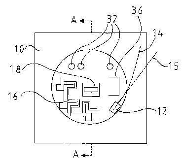
The contact device thus comprises a carrier member 10. In the
shown embodiment, the carrier member (see Fig 2) has an upper
part 10a and a lowered part 10b. The carrier member 10, and
CA 02405243 2002-10-03
WO 01/79905 PCT/SE01/00577
9
thereby the contact device, is according to an advantageous use
suitably fixed to a structural element 20 in a room 22 or in another
part 22 of a building (see Fig 5). Suitably, the structural element 20
is a wall. As is shown in Fig 5, the contact device is suitably
designed such that it may be fixed at least partly lowered relative to
a main surface 24 of the wall 20, which main surface faces the room
22 or the part 22 of the building. As has been mentioned above, it is
also possible that the contact device is fixed at for example a wall
20 without being lowered into the wall 20 itself. The contact device
may thereby comprise a box that simply may be secured by screws
against a wall surface. The box may thereby be designed such that
sensitive components are protected in the same.
A receiving unit 12 is fixed at the carrier member 10. This receiving
unit 12 is designed such that an end of at least one optical fibre 14
may be arranged therein (for the sake of clarity, the fibre is only
shown in Fig 1 and 3). It should be noted that typically at least two
fibres are arranged in the receiving unit 12. Suitably one fibre may
thereby be used to transmit signals and one fibre may be used to
receive signals. Within the scope of the invention is however the
possibility that only one fibre or more than two fibres are used.
When in the description below, for the sake of simplicity, an optical
fibre is described, this should be interpreted such that it may in fact
be more than one fibre.
The receiving unit 12 may consist of a so-called ferrule. This may
also comprise a detector for detecting incoming optical pulses and a
transmitter, for example a laser, for transmitting optical pulses.
Alternatively, such a detector and transmitter may be arranged
separate from the receiving unit 12 and thus only be connected to
the receiving unit 12. The receiving unit 12 is fixed such that it may
receive the optical fibre 14 when this at least one optical fibre 14 is
led to the contact device via the structural element 20, i.e. via the
wall. The optical fibre 14 is thus suitably drawn to the room 22
without being drawn in the room 22 itself. It should however be
noted that within the scope of the invention is the possibility that the
optical fibre 14 is drawn to the contact device in the room 22 itself.
CA 02405243 2002-10-03
WO 01/79905 PCT/SEO1/00577
This may for example be the case when the contact device is fixed
at the wall 20 without being lowered into the wall 20. The optical
fibre 14 may thereby be drawn to the contact device through the
room 22 itself. The optical fibre or fibres 14 may thereby lie
5 protected within a casing. Such a casing may for example already
be arranged around the fibres or the casing may consist of a tube
that is arranged along for example the wall 20 or the floor in the
room 22 for protecting the fibres.
10 The receiving unit 12 is designed to receive said optical fibre 14 in
a direction 15 that is determined by in which position the receiving
unit 12 is fixed at the carrier member 10. This direction 15 thus
defines a straight line. The receiving unit 12 is fixed at the carrier
member 10 such that, when the contact device is fixed in position at
said stuctural element 20, the line 15 forms an angle relative to said
main surface 24 that is less than 45 degrees. Preferably, the angle
is less than 30 degrees. It is also possible that the angle is
essentially 0 degrees. This means thus that said direction 15 is
essentially parallel to the main surface 24 of the wall 22. This
simplifies the fixation of the optical fibre 14 without it being subject
to undesired bending.
The contact device also comprises support members 26 arranged to
enable winding (see Fig 3) of excess of said optical fibre 14.
Suitably, the carrier member 10 comprises recesses or holes 28 for
allowing the optical fibre 14 to be introduced in through a part of the
carrier member 10 to the receiving unit 12. The support members
26 are suitably arranged such that the optical fibre 14 may be
wound such that the wound fibre 14 is arranged essentially parallel
to the main surface 24 of the wall 22 and such that the wound fibre
14 is well protected in a recess 38 in the wall 20. In case the
contact device is fixed at the wall 20 without being lowered therein,
the wound fibre 14 is suitably positioned protected in a box that
forms a protective casing of the contact device.
Furthermore, the receiving unit 12 is preferably arranged at a
distance, for example 1-5 cm, preferably 2-4 cm, from an imaginary
CA 02405243 2002-10-03
WO 01/79905 PCT/SE01/00577
11
central axis 30 (see Fig 2) through the contact device, which central
axis 30 is perpendicular to the main surface 24 of the wall. The
receiving unit 12 is preferably arranged such that said line 15 is
essentially tangential or at least deviates with less than 30 degrees
from the tangent, to an imaginary circle that passes through the
receiving unit 12, wherein the circle is such that it lies in a plane
that is perpendicular to said central axis 30 and such that the centre
of the circle coincides with said central axis 30. The optical fibre 14
may thereby be led from the support members 26 to the receiving
unit 12 without being the subject of undesired bendings.
The contact device also comprises a control circuit 16 (symbolically
marked in Fig 1) that includes a converter for converting optical
signals, that are received via the optical fibre 14, to electrical
signals and for converting electrical signals to optical signals that
are to be transmitted via the optical fibre 14. The receiving unit 12
is connected to the control circuit 16. As has been mentioned
above, parts of the converter may possibly instead be included in
the receiving unit 12. It should be noted that such a control circuit
16 with optoelectric converter is known per se and will therefore not
be described more closely in this description.
The contact device also comprises a first contact member 18 that is
connected to the control circuit 16 such that electrical signals from
the converter are conducted to the first contact member 18 and
such that electrical signals from the first contact member 18 are
conducted to the converter. The first contact member 18 may for
example be a female contact according to some suitable standard,
for example according to RJ or AUI. As has been mentioned above,
it is also possible that the contact device comprises more than one
of said first contact members 18. The contact device may thus for
example be provided with two or more female contacts such that
several apparatuses in the room may be connected to the contact
device and thereby to the optical fibre or fibres that are drawn to the
contact device.
CA 02405243 2002-10-03
WO 01/79905 PCT/SE01/00577
12
The first contact member 18 is designed such that a second contact
member (not shown) may be connected to the first contact member
18 to conduct electrical signals from and to the first contact member
18. The second contact member may thus be a male contact of the
same standard as the first contact member. The receiving unit 12,
the control circuit 16 and the first contact member 18 are fixed
relative to the carrier member 10.
The contact device also comprises indication means 32 that are
connected to said control circuit 16 for indicating different states of
the contact device. These indication means 32 may for example be
light emitting diodes. The indication means 32 may for example
indicate whether transmission or reception is going on and if current
supply to the control circuit 16 is the case.
The contact device also comprises a protective part 34 that is
suited to be fixed relative to said carrier member 10. When the
contact device is fixed at for example a wall 20 and the protective
part 34 is fixed relative to the carrier member 10, the control circuit
16, the receiving unit 12 and the optical fibre 14 are not available to
a person that is in the room 22. Such a person thus "sees" only the
first contact member 18 (or several such contact members if the
contact device includes more than one such contact member). The
sensitive parts of the contact device are thus protected.
The contact device may also comprise a holding member 36 for
holding a battery that may be used to provide the control circuit 16
with a supply voltage. Such a battery may for example be used as a
back-up if other current supply does not work. According to a non-
shown alternative, the holding member 36 may be arranged at the
contact device such that the battery is available to a user that is in
the room 22 without the user having to remove the protective part
34. A user may in this manner in a simple way exchange the
battery.
CA 02405243 2002-10-03
WO 01/79905 PCT/SE01/00577
13
As is shown in Fig 5, the structural element 20, which may be a
wall, is preferably provided with a recess 38, wherein the contact
device is arranged at least partly lowered in the recess 38.
The control circuit 16 may suitably be of the kind that is powered
with a low direct current voltage of for example 6V. In order to
provide the contact device with this supply voltage, it may be
connected to a transformer 40 (see Fig 6). The transformer 40 may
also be what is often called a battery eliminator. The transformer 40
may be fixed at the structural element 20. As is shown in Fig 6, the
transformer 40 may be arranged lowered into the structural element
20. Alternatively, the transformer 40 may be arranged at a distance
from the structural element 20. The transformer 40 may of course
also be fixed at the structural element 20 without being lowered
therein. It is also possible that the transformer is designed as a plug
such that it may be directly plugged into an AC wall contact of a
standard form. From such a transformer, a wire may be drawn to
the contact device for providing the contact device with supply
voltage. Possibly, the contact device may thereby be fixed near or
next to the AC wall contact.
The transformer 40 may connected to a cable 42 that forms part of
the "common" alternating current mains (of for example 110 V or
220 V) and that is already drawn to the structure element 20.
Alternatively, the transformer 40 may be provided with supply
voltage via an electrically conductive telephone line 44 that also
may already have been drawn to the structural element 20. Over
such a telephone line 44 for example a DC-voltage of 40-50V may
be provided.
According to an alternative, the contact device may be connected to
an electric line 46 (see Fig 5) that is drawn to the structural element
20. Such an electric line 46 may for example be drawn to the
structural element 20 when the fibre 14 is drawn. The electric line
46 may also consist of an already provided not used electric
telephone line. The electric line 46 may in turn be connected to a
supply unit, for example in the form of a transformer, that provides
CA 02405243 2002-10-03
WO 01/79905 PCT/SE01/00577
14
the contact device with a suitable supply voltage and that is
positioned at a distance from the structural element 20. Such a
supply unit may for example be arranged in the basement of a
house and provide many contact devices in the house or in the area
with suitable supply voltage. The contact device may according to
one alternative also be connected to a battery that functions as a
back-up and that is positioned at a distance from the structural
element 20, for example in the basement or in another room in a
house. If such a battery is the case, there is no need for a battery
back-up at the contact device itself.
As is schematically shown in Fig 7, the contact device may be
connected to a supervisory system 50 ("management system"), with
the help of which system 50 the function of the contact device may
be supervised. The one responsible for the system with fibres and
contact devices may thereby supervise the function of these. For
example, it may thereby be supervised if the supply voltage to the
contact device functions, if transmission and/or reception is the
case, etc.
The supervisory system 50 may be connected to the control circuit
16 and thereby to the contact device in different manners that are
symbolised in Fig 7. The connection may for example be via an
already existing line 42 intended for AC-voltage, via an optical fibre
14, via an electric telephone line 44 that already is drawn to the
structural element 20, via another line 46 that provides the contact
device with supply voltage or via a separate line 52 drawn
particularly in order to constitute a connection to the supervisory
system.
The invention is not limited to the described embodiments but may
be varied and modified within the scope of the claims.