Language selection

Search

Patent 2405538 Summary

Third-party information liability

Some of the information on this Web page has been provided by external sources. The Government of Canada is not responsible for the accuracy, reliability or currency of the information supplied by external sources. Users wishing to rely upon this information should consult directly with the source of the information. Content provided by external sources is not subject to official languages, privacy and accessibility requirements.

Claims and Abstract availability

Any discrepancies in the text and image of the Claims and Abstract are due to differing posting times. Text of the Claims and Abstract are posted:

  • At the time the application is open to public inspection;
  • At the time of issue of the patent (grant).
(12) Patent Application: (11) CA 2405538
(54) English Title: APPARATUS FOR LAYING TARPAULIN
(54) French Title: DISPOSITIF DE POSE DE BACHE
Status: Deemed Abandoned and Beyond the Period of Reinstatement - Pending Response to Notice of Disregarded Communication
Bibliographic Data
Abstracts

English Abstract


An apparatus for use in conjunction with a powered vehicle to take up a long
length's wide flexible sheeting material such as may be used in sanitary
landfill sites, the
apparatus having a framework designed to be engaged and transported by a
powered
vehicle, pick up arms extending outwardly at each end of the framework, an
arbor
assembly including a cylindrical mandrel, an oil pump mounted interiorly of
the
cylindrical mandrel, and a hydraulic system mounted at one end of the mandrel.


Claims

Note: Claims are shown in the official language in which they were submitted.

The embodiments of the invention in which an exclusive property or privilege
is
claimed are as follows.
1. An apparatus suitable for use in conjunction with a powered vehicle to lay
out and
take up a long length, wide flexible sheeting material, the apparatus
comprising:
a framework adapted for mounting engagement on a powered vehicle such as to be
carried over a ground surface by the vehicle;
a pick up arm extending outwardly from said framework at each end thereof;
means for mounting a shaft on each of said pick up arms;
an arbor assembly including a cylindrical mandrel;
oil pump means mounted interiorly of said cylindrical mandrel; and
a hydraulic system mounted at one end of said mandrel.
2. The apparatus of Claim 1 wherein said mounting means comprises a first arm
segment having a horizontal component and a vertical component, and a second
arm
segment pivotally connected to said first arm segment, said arm segments
defining
therebetween a rectangular opening when closed.
3. The apparatus of Claim 1 wherein said framework further includes leg stand
means mounted to the framework and positioned rearwardly thereof to maintain
the
apparatus in an upright position when not mounted to a vehicle.
4. The apparatus of Claim 2 further including a storage means within said
framework, said storage means having a door permitting access thereto.
5. The apparatus of Claim 4 further including an electric motor, said electric
motor
being mounted within said storage means.
-5-

6. The apparatus of Claim 4 further including a hydraulic reservoir within
said
storage means.
7. The apparatus of Claim 1 wherein said pick up arm comprises a rectangular
gripping means for gripping said arbor assembly.
-6-

Description

Note: Descriptions are shown in the official language in which they were submitted.


CA 02405538 2002-09-27
APPARATUS FOR LAYING TARPAULIN
FIELD OF THE INVENTION
The present invention relates to an apparatus and more particularly relates to
an
apparatus for covering a large area with a flexible sheeting material.
BACKGROUND OF THE INVENTION
The use of an apparatus for laying down a long length of a flexible material
to
cover a large land area is known in the art. One of the uses for such an
apparatus is to
temporarily cover a sanitary landfill site when it is not being worked and to
remove the
material when it is designed to work the area.
Many sanitary landfill sites have regulations which require that the fill not
be left
exposed due to the inherent problems of sanitation. Accordingly, many of the
sanitary
landfill sites are required to cover the same with a layer of soil. This
requires a
substantial expenditure and results in a plurality of layers of landfill and
soil.
Alternatively, the personnel at the site may manually position a flexible
sheeting
material over the area which thus meets the legal requirement. However, this
requires
that the personnel work in contact with the debris or refuse which was dumped
into the
landfill site.
SUMMARY OF THE INVENTION
It is an object of the present invention to provide an apparatus which will be
capable of laying out long sheets of a flexible sheeting material.
According to one aspect of the present invention, there is provided an
apparatus
suitable for use in conjunction with a powered vehicle to lay out and take up
a long
length, wide flexible sheeting material, the apparatus comprising a framework
adapted
-1-

CA 02405538 2002-09-27
for mounting engagement on a powered vehicle such as to be carried over a
ground
surface by the vehicle, a pick up arm extending outwardly from the framework
at each
end thereof, means for mounting a shaft on each of the pick up arms, an arbor
assembly
including a cylindrical mandrel, oil pump means mounted interiorly of the
cylindrical
mandrel, and a hydraulic system mounted at one end of the mandrel.
The apparatus of the present invention may be used in conjunction with
conventional powered equipment such as tractors to provide the ability to
cover a surface
with flexible sheeting material. Such a surface can be, for example, a
sanitary landfill
site. The apparatus is also designed to pick up the sheeting material when
required.
The apparatus of the present invention provides an efficient and economic
solution
for the cover of landfill sites. In lieu of placing soil on top of the
landfill, one can utilize
the sheeting material and thereby increase by 10% to 15% the volume of
material within
the landfill site. This also substantially reduces the cost involved and
thereby becomes an
economic solution for dealing with such landfill sites.
BRIEF DESCRIPTION OF THE DRAWINGS
Having thus generally described the invention, reference will be made to the
accompanying drawings illustrating an embodiment thereof, in which:
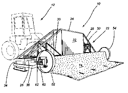
Figure 1 is a perspective view of an apparatus according to the present
invention
as used with power driven equipment, shown in phantom lines;
Figure 2 is a side elevational view showing the apparatus about to be picked
up by
powered equipment and a load of sheet material loaded thereon;
Figures 3 and 4 are side elevational views showing the operation of the
apparatus;
Figure 5 is an enlarged perspective view of the end of the arbor assembly;
-2-

CA 02405538 2002-09-27
Figure 6 is a partial front elevational view of the arbor and framework;
Figure 7 is a top plan view of a portion of the arbor and sheeting material as
it is
placed on a substrate; and
Figure 8 is a cross sectional view illustrating the end portions of the arbor
assembly.
DESCRIPTION OF THE PREFERRED EMBODIMENTS
Referring to the drawings in greater detail and by reference characters
thereto,
there is illustrated in Figure 1 an apparatus according to an embodiment of
the present
invention and which apparatus is generally designated by reference numeral 10.
Apparatus 10 is designed to be used in conjunction with a tractor generally
designated by
reference numeral 12 and which is shown in outline. Tractor 12 includes a
shovel 14
connected to tractor 12 by means of arms 16. Preferably, there is provided an
upper
extension 18.
In general terms, apparatus 10 includes a framework 22 which includes upper
horizontal frame members 24 and lower horizontal frame members 26. A plurality
of
diagonal frame members 28 extend from respective ends of upper frame members
24 to
respective ends of lower horizontal frame members 26. As is conventional,
struts 30
interconnect the frame members.
Framework 22 also includes an enclosed center generally designated by
reference
numeral 32 and which is designed to house various hydraulic components and
parts. In
effect, center portion 32 forms a storage cabinet and which may be accessed by
means of
doors (not shown).
-3-

CA 02405538 2002-09-27
At the end of framework 22 there are provided a rectangular side frame
generally
designated by reference numeral 34. A further side frame (not shown) is
provided on the
other side of framework 22. A side arm 36 extends outwardly and forwardly from
framework 22 (at both ends) and there is provided a grasping mechanism 38.
Grasping mechanism 38 includes a lower arm 40, a vertical arm 42, and an upper
pivotable member 44 which is pivotably connected to vertical arm 42 at pivot
point 46.
A mandrel 50 is provided around which the sheet material is rolled while at
either
end of mandrel 50 there is provided a disk 52, 54.
As may be best seen in Figure 8, a hydraulic motor 56 is connected to disk 52
and
is mounted in a housing 58. Hydraulic motor 56 has hydraulic hoses 60, 62
meeting
thereto and which are supplied from the hydraulic system of tractor 12.
Hydraulic motor 56 is secured to the central part of disk 52 by means of bolts
80
while disk 52 is in turn secured to mandrel 50 by means of bolts 82.
Located interiorly of central portion 32 is a hydraulic reservoir 64. Also
located
therein is a starter 68 and an electric motor 70. Batteries 72 are also
mounted therein.
As may be seen in Figures 2, 3 and 4, the tractor 12 can pick up the apparatus
10
by means of shovel 14 with extension 18. As is illustrated in Figure 3, the
apparatus can
be moved to the desired location. Subsequently, as shown in Figure 4, a film
or sheeting
material may be dispensed as indicated by arrow 76. Naturally, the operation
may be
reversed when it is desired to take up the sheeting material 74.
It will be understood that the above described embodiments are for purposes of
illustration only and changes or modifications may be made thereto without
departing
from the spirit and scope of the invention.

Representative Drawing
A single figure which represents the drawing illustrating the invention.
Administrative Status

2024-08-01:As part of the Next Generation Patents (NGP) transition, the Canadian Patents Database (CPD) now contains a more detailed Event History, which replicates the Event Log of our new back-office solution.

Please note that "Inactive:" events refers to events no longer in use in our new back-office solution.

For a clearer understanding of the status of the application/patent presented on this page, the site Disclaimer , as well as the definitions for Patent , Event History , Maintenance Fee  and Payment History  should be consulted.

Event History

Description Date
Revocation of Agent Requirements Determined Compliant 2021-04-01
Application Not Reinstated by Deadline 2011-03-15
Inactive: Dead - No reply to s.30(2) Rules requisition 2011-03-15
Deemed Abandoned - Failure to Respond to Maintenance Fee Notice 2010-09-27
Inactive: Abandoned - No reply to s.30(2) Rules requisition 2010-03-15
Inactive: S.30(2) Rules - Examiner requisition 2009-09-15
Letter Sent 2007-10-15
All Requirements for Examination Determined Compliant 2007-09-13
Request for Examination Received 2007-09-13
Request for Examination Requirements Determined Compliant 2007-09-13
Inactive: IPC from MCD 2006-03-12
Application Published (Open to Public Inspection) 2004-03-27
Inactive: Cover page published 2004-03-26
Inactive: First IPC assigned 2002-11-27
Application Received - Regular National 2002-11-08
Filing Requirements Determined Compliant 2002-11-08
Inactive: Filing certificate - No RFE (English) 2002-11-08
Small Entity Declaration Determined Compliant 2002-09-27

Abandonment History

Abandonment Date Reason Reinstatement Date
2010-09-27

Maintenance Fee

The last payment was received on 2009-09-16

Note : If the full payment has not been received on or before the date indicated, a further fee may be required which may be one of the following

  • the reinstatement fee;
  • the late payment fee; or
  • additional fee to reverse deemed expiry.

Please refer to the CIPO Patent Fees web page to see all current fee amounts.

Fee History

Fee Type Anniversary Year Due Date Paid Date
Application fee - small 2002-09-27
MF (application, 2nd anniv.) - small 02 2004-09-27 2004-09-16
MF (application, 3rd anniv.) - small 03 2005-09-27 2005-09-26
MF (application, 4th anniv.) - small 04 2006-09-27 2006-09-27
Request for examination - small 2007-09-13
MF (application, 5th anniv.) - small 05 2007-09-27 2007-09-24
MF (application, 6th anniv.) - small 06 2008-09-29 2008-09-19
MF (application, 7th anniv.) - small 07 2009-09-28 2009-09-16
Owners on Record

Note: Records showing the ownership history in alphabetical order.

Current Owners on Record
JEAN-YVES VOGHEL
Past Owners on Record
None
Past Owners that do not appear in the "Owners on Record" listing will appear in other documentation within the application.
Documents

To view selected files, please enter reCAPTCHA code :


To view images, click a link in the Document Description column. To download the documents, select one or more checkboxes in the first column and then click the "Download Selected in PDF format (Zip Archive)" or the "Download Selected as Single PDF" button.

List of published and non-published patent-specific documents on the CPD .

If you have any difficulty accessing content, you can call the Client Service Centre at 1-866-997-1936 or send them an e-mail at CIPO Client Service Centre.


Document
Description 
Date
(yyyy-mm-dd) 
Number of pages   Size of Image (KB) 
Representative drawing 2003-01-20 1 18
Abstract 2002-09-27 1 16
Description 2002-09-27 4 182
Claims 2002-09-27 2 50
Drawings 2002-09-27 4 110
Cover Page 2004-03-02 1 41
Filing Certificate (English) 2002-11-08 1 161
Reminder of maintenance fee due 2004-05-31 1 109
Reminder - Request for Examination 2007-05-29 1 118
Acknowledgement of Request for Examination 2007-10-15 1 189
Courtesy - Abandonment Letter (R30(2)) 2010-06-07 1 164
Courtesy - Abandonment Letter (Maintenance Fee) 2010-11-22 1 172
Fees 2004-09-16 1 24
Fees 2005-09-26 1 21
Fees 2006-09-27 1 49