Note: Descriptions are shown in the official language in which they were submitted.
CA 02405743 2002-10-08
WO 01/78471 PCT/GB01/01545
Twin Plasma Torch Apparatus
The invention relates to a twin plasma torch
apparatus.
In a twin plasma torch apparatus, the two torches
are oppositely charged i.e. one has an anode electrode
and the other a cathode electrode. In such apparatus,
the arcs generated by each electrode are coupled
together in a coupling zone remote from the two
torches. Plasma gases are passed through each torch
and are ionised to form a plasma which concentrates in
the coupling zone, away from torch interference.
Material to be heated/melted may be directed into
this coupling zone wherein the thermal energy in the
plasma is transferred to the material. Twin plasma
processing can occur in open or confined processing
zones.
Twin plasma apparatus are often used in furnace
applications and have been the subject of previous
patent applications, for example EP0398699 and
US5256855.
The twin arc process is energy efficient because
as the resistance of the coupling between the two arcs
increases remote from the two torches, the energy is
increased but torch losses remain constant. The
process is also advantageous in that relatively high
temperatures are readily reached and maintained. This
is attributable to both the fact that the energy from
the two torches is combined and also because of tHe
above mentioned efficiency.
However, such processes have disadvantages. If
the plasma torches are in close proximity to one
another and/or are enclosed within a small space,
CA 02405743 2008-09-26
20086-2264
2 -
there is a tendency for the arcs to destabilise,
particularly at higher voltages. This side-arcing occurs
when the arcs preferentially attach themselves to lower
resistance paths.
The problem of side-arcing in current twin torch
apparatus has lead to the development of open processing
units in which the plasma torches are substantially spaced
apart, with low resistance paths removed from vicinity, as
described in US 5,104,432. In such units, the process gas
is free to expand in all directions in these applications.
However, such arrangements are not suitable for all
processing applications, particularly when expansion of
process gases needs to be controlled e.g. production of
ultra fine powders.
In current systems with confined processing zones,
the torch nozzles project into the chamber so that the
chamber walls, which have a low resistance, are removed from
the vicinity of the plasma arc. This awkward construction
inhibits side-arcing and encourages coupling of the arcs.
However, the protruding nozzles provide surfaces on which
melted material may precipitate. This not only results in
wastage of material but shortens the life of the torches.
The present invention provides a twin plasma torch
assembly comprising:
(a) at least two plasma torch assemblies of opposite
polarity supported in a housing, said assemblies being
spaced apart from one another and comprising
(i) a first electrode in a first torch assembly;
(ii) a second electrode in a second torch assembly
which is or is adapted to be spaced apart from the first
CA 02405743 2008-09-26
20086-2264
3 -
electrode by a distance sufficient to achieve a plasma arc
therebetween in a processing zone;
(b) means for introducing a plasma gas into the processing
zone around each electrode;
(c) means for introducing shroud gas to surround the plasma
gas;
(d) means for supplying feed material into the processing
zone; and
(e) means for generating a plasma arc in the processing
zone;
wherein distal ends of the first and second
electrodes do not project beyond the housing.
The shroud gas confines the plasma gas, inhibits
side-arcing, and increases plasma density. The invention
therefore provides an assembly in which the torches are
inhibited from side-arcing, and thus facilitates the
miniaturisation of torch design where distance to low
resistance paths are small. The use of shroud gas can also
eliminate the need for torch nozzles to extend beyond the
housing.
The shroud gas may be provided at various
locations along the electrodes, particularly in cylindrical
torches where arcs are generated along the length of the
electrodes. However, preferably, each torch has a distal
end for the discharge of plasma gas and the means for
supplying shroud gas provides shroud gas downstream of the
distal end of each electrode. Therefore, reactive gases
such as oxygen may be added to the plasma without degrading
the electrode. The
CA 02405743 2002-10-08
WO 01/78471 PCT/GB01/01545
- 4 -
practical applicability of plasma torches is increased
by the facility to add reactive gases downstream of
the electrode.
In a preferred embodiment, each plasma torch
comprises a housing which surrounds the electrode to
define a shroud gas supply duct between the housing
and the electrodes, wherein the end of the housing is
tapered inwards towards the distal end of the torch to
direct flow of the shroud gas around the plasma gas.
The twin plasma torch assembly of the present
invention may be used in an arc reactor having a
chamber to carry out a plasma evaporation process to
produce ultra-fine (i.e. sub-micron or nano-sized)
powders, for example aluminium powders. The reactor
may also be used in a spherodisation process.
The chamber will typically have an elongate or
tubular form with a plurality of orifices in a wall
portion thereof, a twin plasma torch assembly being
mounted over each orifice. The orifices, and thus the
twin plasma torch assemblies, may be provided along
and/or around said tubular portion. The orifices are
preferably provided at substantially regular
intervals.
The distal ends of the first and/or second
electrodes, for the discharge of plasma gas will
typically be formed from a metallic material, but may
also be formed from graphite.
The plasma arc reactor preferably further
comprises cooling means for cooling and condensing
material which has been vaporised in the processing
zone. The cooling means comprises a source of a
cooling gas or a cooling ring.
CA 02405743 2002-10-08
WO 01/78471 PCT/GB01/01545
- 5 -
The plasma arc reactor will typically further
comprise a collection zone for collecting processed
feed material. The process feed material will
typically be in the form of a powder, liquid or gas.
The collection zone may be provided downstream of
the cooling zone for collecting a powder of the
condensed vaporised material. The collection zone may
comprise a filter cloth which separates the powder
particulate from the gas stream. The filter cloth is
preferably mounted on an earthed cage to prevent
electrostatic charge build up. The powder may then be
collected from the filter cloth, preferably in a
controlled atmosphere zone. The resulting powder
product is preferably then sealed, in inert gas, in a
container at a pressure above atmospheric pressure.
The plasma arc reactor may further comprise means
to transport processed feed material to the collection
zone. Such means may be provided by a flow of fluid,
such as, for example, an inert gas, through the
chamber, wherein, in use, processed feed material is
entrained in the fluid flow and is thereby transported
to the collection zone.
The means for generating a plasma arc in the
space between the first and second electrodes will
generally comprise a DC or AC power source.
The apparatus according to the present invention
may operate without using any water-cooled elements
inside the plasma reactor and allows replenishment of
feed material without stopping the reactor.
The means for supplying feed material into the
processing zone may be achieved by providing a
material feed tube which is integrated with the
CA 02405743 2002-10-08
WO 01/78471 PCT/GB01/01545
- 6 -
chamber and/or the twin torch assembly. The material
may be particulate matter such as a metal or may be a
gas such as air, oxygen or hydrogen or steam to
increase the power at which the torch assembly
operates.
Advantageously, the distal ends of first and
second electrodes, for the discharge of plasma gas, do
not project into the chamber.
The small size of the compact twin torch
arrangement according to the present invention allows
many units to be installed onto a product transfer
tube. This enables easy scale-up to typically over 10
times to give a full production unit without scale up
uncertainty.
The present invention also provides a process for
producing a powder from a feed material, which process
comprises:
(A) providing a plasma arc reactor as herein defined;
(B) introducing a plasma gas into the processing
zones between the first and second electrodes;
(C) generating a plasma arc in the processing zones
between the first and second electrodes;
(D) supplying feed material into the plasma arcs,
whereby the feed material is vaporised;
(E) cooling the vaporised material to condense a
powder; and
(F) collecting the powder.
CA 02405743 2002-10-08
WO 01/78471 PCT/GB01/01545
- 7 -
The feed material will generally comprise or
consist of a metal, for example aluminium or an alloy
thereof. However, liquid and/or gaseous feed
materials can also be used. In the case of a solid
feed, the material may be provided in any suitable
form which allows it to be fed into the space between
the electrodes, i.e, into the processing zone. For
example, the material may be in the form of a wire,
fibres and/or a particulate.
The plasma gas will generally comprise or consist
of an inert gas, for example helium and/or argon.
The plasma gas is advantageously injected into
the space between the first and second electrodes,
i.e. the processing zone.
At least some cooling of the vaporised material
may be achieved using an inert gas stream, for example
argon and/or helium. Alternatively, or in combination
with the use of an inert gas, a reactive gas stream
may be used. The use of a reactive gas enables oxide
and nitride powders to be produced. For example,
using air to cool the vaporised material can result in
- the production of oxide powders, such as aluminium
oxide powders. Similarly, using a reactive gas
comprising, for example, ammonia can result in the
production of nitride powders, such as aluminium
nitride powders. The cooling gas may be recycled via
a water-cooled conditioning chamber.
The surface of the powder may be oxidised using a
passivating gas stream. This is particularly
advantageous when the material is a reactive metal,
such as aluminium or is aluminium-based. The
passivating gas may comprise an oxygen-containing gas.
CA 02405743 2002-10-08
WO 01/78471 PCT/GB01/01545
- $ -
It will be appreciated that the processing
conditions, such as material and gas feed rates,
temperature and pressure, will need to be tailored to
the particular material to be processed and the
desired size of the particles in the final powder.
It is generally preferable to pre-heat the
reactor before vaporising the solid feed material. The
reactor may be preheated to a temperature of at least
about 2000 C and typically approximately 2200 C. Pre-
heating may be achieved using a plasma arc.
The rate at which the solid feed material is fed
into the channel in the first electrode will affect
the product yield and powder size.
For an aluminium feed material, the process
according to the present invention may be used to
produce a powdered material having a composition based
on a mixture of aluminium metal and aluminium oxide.
This is thought to arise with the oxygen addition made
to the material during processing under low
temperature oxidation conditions.
- Specific embodiments of the present invention
will now be described in detail with reference to the
following figures (drawn approximately to scale) in
which:
Figure 1 is a cross section of a cathode torch
assembly;
Figure 2 is a cross section of an anode torch
assembly;
Figure 3 shows a portable twin torch assembly
comprising the anode and cathode torch assemblies of
CA 02405743 2002-10-08
WO 01/78471 PCT/GB01/01545
- 9 -
Figures 1 and 2, mounted onto a confined processing
chamber;
Figure 4 shows the portable twin torch assembly
of Figure 3 mounted into a housing;
Figure 5 is a schematic of the assembly of Figure
3 when used to produce ultra fine powders;
Figures 6A is a schematic of the assembly of
Figure 4 configured to operate in transferred arc to
arc coupling mode, with a anode target;
Figure 6B is a schematic of the assembly of
Figure 4 configured to operate in transferred arc
mode, with a anode target;
Figures 7A is a schematic of the assembly of
Figure 4 configured to operate in transferred arc to
arc coupling mode, with a cathode target;
Figure 7B is a schematic of the assembly of
Figure 4 configured to operate in transferred arc
mode, with a cathode target.
_
Figures 1 and 2 are cross sections of assembled
cathode 10 and anode 20 torch assemblies respectively.
These are of modular construction each comprising an
electrode module 1 or 2, a nozzle module 3, a shroud
module 4, and a electrode guide module 5.
Basically, the electrode module 1, 2 is in the
interior of the torch 10, 20. The electrode guide
module 5 and the nozzle module 3 are axially spaced
apart surrounded the electrode module 1,2 at locations
along its length. At least the distal end (i.e. the
end from which plasma is discharged from the torch) of
CA 02405743 2002-10-08
WO 01/78471 PCT/GB01/01545
- 10 -
the electrode module 1, 2 is surrounded by the nozzle
module 3. The proximal end of the electrode module 1
or 2 is housed in the electrode guide module 5. The
nozzle module 3 is housed in the shroud module 4.
Sealing between the various modules and also the
module elements is provided by "0" rings. For example,
"0" rings provide seals between the nozzle module 3
and both the shroud module 4 and electrode guide
module 5. Throughout the figures of the specification,
"0" rings are shown as small filled circles within a
chamber.
Each torch 10, 20 has ports 51 and 44 for entry
of process gas and shroud gas respectively. Entry of
process gas is towards the proximal end of the torch
10, 20. Process gas enters a passage 53 between the
electrode 1 or 2 and the nozzle 3 and travels towards
the distal end of the torch 10, 20. In this particular
embodiment, shroud gas is provided at the distal end
of the torch 10, 20. This keeps shroud gas away from
the electrode and is particularly advantageous when
using a shroud gas which may degrade the electrode
modules 1, 2, e.g. oxygen. However, in other
embodiments, the shroud gas could enter towards the
proximal end of the torch 10, 20.
The shroud module 4 is fitted at the distal end
of the torch 10, 20. The shroud module 4 comprises a
nozzle guide 41, a shroud gas guide 42, an electrical
insulator 43, a chamber wall 111, and also a seat 46.
An "0" ring is provided to seal the chamber wall 111
and the nozzle guide 41. Optionally, coolant fluid may
also be transported within the chamber wall 111.
The electrical insulator 43 is located on the
chamber wall 111 such that there is no low resistance
CA 02405743 2002-10-08
WO 01/78471 PCT/GB01/01545
- 11 -
path at the distal end of the*torch to facilitate arc
destabilisation. The electrical insulator 43 is
typically made of boron nitride or silicon nitride.
The shroud gas guide 42 is located on the
electrical insulator 43 and provides support for the
distal end of the nozzle module 3 and also allows flow
of shroud gas out of the distal end of the torch. It
is typically made from PTFE.
The nozzle guide 41 is made of an electrical
insulator, such as PTFE, and is used to locate the
nozzle module 3 in the shroud module 4. The nozzle
guide 41 also contains a passage 44 through which
shroud gas is fed to an chamber 47. Shroud gas exits
from the chamber 47 through passages 45 located in the
shroud gas guide 42. These passages 45 are along the
contact edge with the electrical insulator 43.
Although shroud gas is shown to be delivered to
the torch 10, 20 using a specific arrangement for the
shroud gas module 4 (Figure 8), delivery may be by
other means. For example, shroud gas may be delivered
near the proximal end of the torch, through a passage
_ surrounding the process gas passage 51. The shroud gas
may also be delivered to an annular ring located at
and offset from the distal end of the torch.
The electrode guide module 5 conveniently
provides a passage or port 51 for the entry of process
gas. The internal proximal end of the nozzle module 3
is advantageously chamfered to direct flow of process
gas from the passage 51 into the nozzle module 3 and
around the electrode.
The electrode guide module 5 needs to be
correctly circumferentially aligned such that the
CA 02405743 2002-10-08
WO 01/78471 PCT/GB01/01545
- 12 -
electrode guide cooling circuit and the torch cooling
circuit (discussed below) align.
The nozzle module 3 and electrode modules 1 and 2
have cooling channels for the circulation of cooling
fluid. The cooling circuits are combined into a single
circuit in which cooling fluid enters the torch
through an single torch entry port 8 and exits torch
out of a single torch exit port 9. The cooling fluid
enters through the entry port 8 travels through the
electrode module 1, 2 to the nozzle module 3, and then
exits out of the torch through a nozzle exit port 9.
The fluid which leaves the nozzle exit port 9 is
transported to a heat exchanger to provide cooled
fluid which is recirculated to the entry port 8.
Looking at the flow of cooling fluid through the
modules in detail, fluid entering from the torch entry
port 8 is directed to an electrode entry port 81.
Cooling fluid enters the electrode near its proximal
end and travels along a central passage to the distal
end wherein it is redirected back to flow along a
surrounding outer passage (or number of passages) and
out of an electrode exit port 91. This fluid enters
- the nozzle at entry port 82 and flows along interior
passages to the distal end of the nozzle. It is then
directed back along surrounding passages to the exit
from the nozzle port 92. The fluid is directed to the
torch exit port 9.
Any fluid which acts as an effective coolant may
be used in the cooling circuit. When water is used,
the water should preferably be de-ionised water to
provide a high resistance path to current flow.
The torches 10 and 20 may be used for twin plasma
torch assemblies, in both open and confined processing
CA 02405743 2002-10-08
WO 01/78471 PCT/GB01/01545
- 13 -
zone chambers. The construction of confined processing
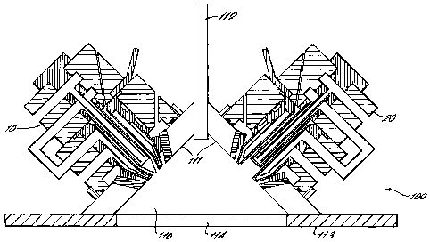
zone twin plasma torch assembly 100 is shown in Figure
9.
The assembly 100 is configured to provide torches
10, 20 which are easily installed to the correct
position for operation. For example, the offset
between the distal ends of the electrodes 1, 2 and the
angle between them are determined by the dimensions of
the assembly components.
The torch and assembly modules are constructed
to close tolerance to provide good fitting between the
modules. This would limit radial movement of one
module within another module. To allow ease of
assembly and re-assembly, corresponding modules would
slide into one another and be locked in by for
example, locking pins. The use of locking pins in the
modules would also ensure that each module was
correctly oriented within the torch assemblies ie.
provide circumferential registration.
The confined processing zone twin torch assembly
100 comprises a cathode and anode torch assemblies 10
and 20, and a feed tube 112. Typically, the two
torches are at right angles to one another. The
components are arranged to provide a confined
processing zone 110 in which coupling of the arcs will
occur. The feed tube 112 is used to supply powder,
liquid, or gas feed material into the processing zone
110. The walls 111 of the shroud modules 4
conveniently define the chamber which contains the
confined processing zone 110.
The walls 111 provide a divergent processing zone
110 in which the low resistance wall surfaces are
maintained away from the arcs, inhibiting side-arcing.
CA 02405743 2002-10-08
WO 01/78471 PCT/GB01/01545
- 14 -
In addition, the divergent nature of the design allows
gas expansion after plasma coupling, without a
constrictive pressure build-up.
The walls 111 define a conical chamber which may
comprise curved or flat walls. The perimeter of the
walls 111 may be joined to chamber walls 113 to enable
the assembly 100 to be mounted (Figure 4). In such an
arrangement, there should obviously be an orifice 114
such that the processing zone 110 is not totally
enclosed. Typically, a circular orifice 114 can have a
diameter of 15cm.
The confined processing zone 110 may be made as a
separate module comprising the feed tube 112, and the
chamber walls 111 and 113.
The assembly 100 may be mounted into a cylinder
which comprises (optional) inner cooling walls 115,
surrounded by an outer refractory lining 116 (Figure
4). The lining 116 would preferably be a heat
resistant material. The walls 111 may themselves also
have integrated cooling channels.
- Turning now to the operation of the torches 10,
20, a shroud gas is provided to encircle the arcs
generated from the electrodes. The shroud gas may be
helium, nitrogen or air. Any gas which provides a high
resistance path to prevent the arc from travelling
through the shroud is suitable. Preferably, the gas
should be relatively cold. The high resistance path of
the shroud gas concentrates the arc into a relatively
narrow bandwidth. The tapered distal end of the nozzle
module assists in providing a gas shroud which is
directed to encircle the arc.
The shroud gas also acts to confine the plasma
CA 02405743 2002-10-08
WO 01/78471 PCT/GB01/01545
- 15 -
and inhibits melted feed material from being
recirculated back towards the feed tube 112 or the
chamber walls 111. Thus, the efficiency of processing
is increased.
As the distal end of the nozzle no longer
protrudes into the confined processing zone,
precipitation of melted feed material on the nozzle is
inhibited. Thus, the operational life of the nozzle is
prolonged, and the efficiency of the material
processing increased.
Any regions of the assembly which are
particularly close to the arcs are made or coated with
an electrical insulator, for example the shroud gas
guide 42 and the electrical insulator 43.
The invention may be applied to numerous
practical applications, for example to manufacture
nano-powders, spherodisation of powders or the
treatment of organic waste. Some further examples are
given below.
1. Gas Heater/steam generator
-
Due to the modular nature, the invention allows
replacement of existing gas fossil fuel burners with
an electrical gas heater. Introducing water between
the two torches will enable steam to be generated
which may be used to heat existing kilns and
incinerators. Gasses may be introduced between the
arcs to give an efficient gas heater.
2. Pyrolysis/Gas Heating and Reforming
Introduction of liquid and/or gas, and/or solids
into the coupling zone will enable thermal treatment.
CA 02405743 2002-10-08
WO 01/78471 PCT/GB01/01545
- 16 -
3. Reactive Material Processing
Materials which dissociate into chemically
reactive materials may be processed in the unit as
there need not be any reactor wall contact at high
temperatures.
In such cases, the walls 111 of the water cooled
processing zone chamber would have a grated surface to
allow transpiration to occur. This creates a
protective barrier to stop reactive gas impingement.
4. Ultra-fine powder production
The assembly may be utilised to produce ultra
fine powders (generally of unit dimension of less than
200 nanometres) is illustrated in Figure 5. The
small size of the unit enables easy attachment of a
quench ring 130 in close proximity to the gaseous high
temperature plasma coupling zone. Fine powder is
produced in the zone 132, within the expansion zone
131. Higher gas quench velocities produce smaller the
terminal unit dimension of the particles.
- A plurality of twin torch assemblies as herein
described may be mounted on a processing chamber.
It is expected that the nano-powders produced by
this method would produce finer powders as it would be
possible to install the quench apparatus 130 in close
proximity to the arc to arc coupling zone. This would
minimise the time available for the powder/liquid feed
material particles to grow.
It will be appreciated that composite materials may
be fed to make nano-alloy materials.
CA 02405743 2002-10-08
WO 01/78471 PCT/GB01/01545
- 17 -
Introduction of fine powders, gasses or liquids
between the arc will vaporize them and the vapor may then
be quenched/and or reacted to give a powder of nano-sized
powders.
5. Coupled or Transferred Arc Mode
The modular assembly may also be configured as to
operate in transferred arc modes with anode (Figure 6)
and cathode (Figure 7) targets. The torches described
above are suitable for operation in transferred arc to
arc coupling mode (Figures 6A and 7A) and transferred
arc mode (Figures 6B and 7B).
6. Spherodisation
Typical plasma gas temperatures at the arc to arc
coupling zone have been measured to be up to 10,000 K for
an Argon plasma. Introduction of angular particles results
in spherodisation.
7. Thermal modification/Etching/Surface modification
The Coupling zone between the arcs may be used to
thermally modify a feed gas, for example methane,
ethane or UF6.
The plasma plume may also be used to achieve
surface modification by, for example, ion impingement,
melting, or to chemically alter the surface such as in
nitriding.
8. ICP analyses
The assembly according to the present invention
may also be used in ICP analyses and as a high energy
CA 02405743 2002-10-08
WO 01/78471 PCT/GB01/01545
- 18 -
UV light source.
Various modifications can be made to the above
embodiments. For example, cooling water systems of
the two torches may be combined, or one or both of the
torches of the twin apparatus could have a gas shroud.
In addition, the gas shroud may be applied to torches
which do not have the modular construction mentioned
above.
The apex cone angle in the torch assembly may be
different for different applications. In some cases it may
be desirable to fit to a cylinder without a cone.
A plurality of twin torch assemblies as herein
described may be mounted on chamber.