Note: Descriptions are shown in the official language in which they were submitted.
CA 02405789 2002-10-07
WO 01/78838 PCT/USO1/12539
t
RESPIRATORY MASK AND SERVICE MODULE
CROSS-REFERENCE TO RELATED APPLICATION
Applicant hereby claims priority based on U.S.
Provisional Application No. 60/197,762 filed April 17,
2000, entitled "Respiratory Mask With a Modular
Inhalation/Exhalation Valve Assembly" which is
incorporated herein by reference.
FIELD OF THE TNVENTION
This invention.relates to respiratory masks and
service modules suitable for use in pressure breathing
and other applications.
BACKGROUND OF THE INVENTION
High performance, high altitude flying typically
poses several challenges for masks for pressure
breathing. First, high mask pressures make it
relatively difficult to hold the mask on the face with
minimal leakage. Second, the "G" forces combined with
the harnessing and mask pressures tend to cause
discomfort for the user. Third, "G" forces sometimes
cause the mask to lose proper position and to migrate
around the face.
Because of the environment that the mask assembly
is subjected to, namely the pressure differential in
high altitude applications and the forces associated
with High "G" force applications, it is desirable to
minimize the volume of the internal breathing cavity. A
larger breathing gas cavity where pressure is higher
than ambient would create greater forces urging the mask
away from the face of the user thus requiring tighter
restraints to keep the mask on the face.
Accordingly there is a need for an oro-nasal mask
that minimizes the surface area "footprint" of the mask
internal breathing cavity on the face.
With any pressure breathing mask, some force needs
to be exerted on the face to counteract pressure forces
CA 02405789 2002-10-07
WO 01/78838 PCT/USO1/12539
- 2 .
and for harnessing. It is important to exert this force
in a fashion so that it is not localized or causing
pressure points on isolated areas such as the bridge of
the nose.
Also, because varying "G" loads and directions will
magnify any mask weight and attempt to pull it around
the face there is a need for a mask design that is
structurally supported on the face so as to be resistant
to being pulled around the face.
Further, in order to provide a proper seal for
different face sizes and face shapes, it is often
desirable to provide an arrangement so that breathing
conduits or the like can be easily and quickly combined
with more than one size mask.
In addition to the high altitude, high performance
setting, the modular design would also be important to
many other types of masks including, but not limited to,
full facepiece masks, standard half facepiece masks,
half facepiece masks with detachable goggles, or the
like.
SUMMARY OF THE INVENTION
The present invention meets the above-described
need by providing a respiratory mask and service module
combination.
The mask provides a modular arrangement such that
the service module can be used with many different sized
mask assemblies.
The service module is described herein in
connection with a mask assembly suitable for high "G"
force applications. However, as it will be apparent to
those of ordinary skill in the art, the service module
could also be integrated into modular designs for other
types of masks including, but not limited to, full
facepiece masks, standard half facepiece masks, half
facepiece masks with detachable goggles, or the like.
CA 02405789 2002-10-07
WO 01/78838 PCT/USO1/12539
- 3 -
Also, in order to provide a proper seal for
different face sizes and face shapes, it is often
desirable to provide more than one size mask. The
present invention provides for interchanging different
mask assemblies with a single service module.
BRIEF DESCRIPTION OF THE DRAWINGS
The invention is illustrated in the drawings in which
like reference characters designate the same or similar
parts throughout the figures of which:
Fig. 2 is a perspective view of the respiratory
mask and inhalation/exhalation valve assembly of the
present invention;
Fig. 2 is a front elevational view of the
respiratory mask and inhalation/exhalation valve
assembly of the present invention;
Fig. 3 is a perspective view of the half facepiece
mask of the present invention with the
inhalation/exhalation valve assembly removed;
Fig. 4 is a front elevation of the hardshell
subassembly for the half facepiece mask of the present
invention;
Fig. 5 is a perspective view of the hardshell
subassembly for the half facepiece mask of the present
invention;
Fig. 6 is a perspective view of the inside of the
half facepiece respiratory mask;
Fig. 7 is a sectional side view of the mask and
inhalation/exhalation valve assembly taken along lines
7-7 of Fig. 2;
Fig. 8 is a perspective view of an alternate
embodiment of the inhalation/exhalation valve assembly
having an integrally formed tab in the housing for
connecting to straps for holding the mask in position;
Fig. 9A is a perspective view of the
exhalation/inhalation valve body;
CA 02405789 2002-10-07
WO 01/78838 PCT/USO1/12539
- 4 _
Fig. 9B is a front elevation view of the
exhalation/inhalation valve body;
Fig. 10 is a sectional side view of the valve
assembly taken along lines 10-10 of Fig. 9B;
Fig. 11 is an exploded perspective view of the
valve assembly; and,
Fig. 12 is also an exploded perspective view of the
valve assembly.
DETAILED DESCRIPTION
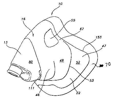
Referring initially to Figs. 1 and 2, a half
facepiece respiratory mask 10 includes an
inhalation/exhalation valve assembly 13 and a half
facepiece mask assembly 16. The inhalation/exhalation
valve assembly 13 of the present invention is one.form
of a service module. The term "service module" is
defined as a module having at least two or more conduits
and designed so as to provide communication between at
least two of the conduits. In the example shown, the
service module is an inhalation/exhalation valve
assembly. Other service applications requiring two
conduits and integrally formed so as to provide
communication therebetween are also part of the
invention. Another example is a communications device
in electrical communication with the inhalation or
exhalation. valve. In the embodiment shown, the valve
assembly 13 is removably attached to the mask assembly
16 as described below and the valve assembly 13 is
capable of being sealed with a single gasket 14 (Fig.
3). The mask 10 provides for a modular arrangement such
that the inhalation/exhalation valve assembly 13 can be
used with different sized mask assemblies 16. The
inhalation/exhalation valve assembly 13 is preferably
contained in a single housing 80. The mask assembly 16
is a half facepiece with a relatively rigid plastic
hardshell member 22 having an elastomeric material 25
CA 02405789 2002-10-07
WO 01/78838 PCT/USO1/12539
- 5 -
bonded thereto. The valve assembly 13 is described
herein in connection with a mask assembly I6 suitable
for high "G" force applications, however, as it will be
apparent to those of ordinary skill in the art, the
valve assembly 13 could also be integrated into modular
designs for other types of masks including but not
limited to full facepiece masks, standard half facepiece
masks, half facepiece masks with detachable goggles, or
the like.
The mask 10 has an inlet 103 for connection to a
breathing gas tube and an outlet 108 (Fig. 10) leading
to an exhalation port 111 for exhalation. The mask 10
can be provided with additional openings 34, 37 for
microphones, drink tubes, anti-suffocation valves, or
the like as shown in Fig. 3. Also, the mask 10 can be
equipped with a single opening to receive the inhalation
and exhalation conduits or a single opening for a pair
of conduits arranged so as to have concentric
passageways for inhalation and exhalation gases as known
to those of ordinary skill in the art.
Turning to Fig. 3, the half facepiece mask assembly
16 has an opening 28 for the inhalation valve, an
opening 31 for the exhalation valve, and a pair of
auxiliary openings 34 and 37, which can be used for
drink tubes, anti-suffocation valves and the like as
mentioned above. The openings are all disposed on a
substantially planar portion 40 that is integrally
formed in the hardshell member 22. The planar portion
40 is described in greater detail hereafter.
The hardshell member 22 is preferably an injection
molded ABS. Suitable plastic materials include
polycarbonate, polysulfone, and other thermoset plastics
or thermoplastics and the like capable of being molded
into a relatively rigid plastic structure, and may
include fillers and additives for additional properties
such as color and the like as known to those of ordinary
CA 02405789 2002-10-07
WO 01/78838 PCT/USO1/12539
- 6 -
skill in the art. The hardshell member 22 is preferably
relatively rigid compared to the elastomer material 25.
The elastomeric material 25 covers most of the hardshell
member 22 on the inside of the mask assembly 16 (as
shown in Fig. 6) and is used wherever the mask contacts
the skin of the wearer.
The elastomeric material 25 preferably comprises
medium density silicone having a durometer of 50-70
shore A. However, other elastomers and the like would
also be suitable such as any liquid injection molded or
compression molded elastomer having suitable bonding and
elastomeric material properties.
In order to make the half facepiece mask assembly
16 shown in Fig. 3, the hardshell member 22 is placed in
a mold and the elastomeric material 25 is molded to the
hardshell member 22 through primarily chemical bonding
during the molding process with some additional support
from mechanical bonding around the hardshell member 22.
The mask assembly 16 is designed such that a sealed
chamber 18 (Fig. 6) capable of receiving pressurized
breathing gas is formed inside a portion of the mask
assembly 16. Because of the environment that the mask
assembly 16 is subjected to, it is desirable to minimize
the volume of this chamber 18. For example, the
pressure differential in high altitude applications and
the forces associated with High G force applications
make it desirable to minimize the volume of the
breathing gas chamber 28. A larger breathing gas
chamber where pressure is higher than ambient would
create greater forces urging the mask away from the face
of the user thus requiring tighter restraints to keep
the mask on the face. Also, when the pilot experiences
high G forces, the pressure of the breathing gas may be
automatically increased, and this additional pressure
increases the above-described forces that urge the mask
away from the wearer's face.
CA 02405789 2002-10-07
WO 01/78838 PCT/USO1/12539
-
As shown in Fig. 6, the chamber 18 is sealed by a
primary faceseal 43 that defines an area that is
substantially less than the size of the entire inside
area of the mask assembly 16. When the mask 10 is
placed on a wearer's face, the primary faceseal 43
extends over the bridge of the nose, around the sides of
the nose and mouth and across the mental protuberance to
subdivide the inside of the mask assembly 16 into a
relatively small chamber that is sealed to confine the
breathing gas.
Returning to Figs. 1-3, the hardshell member 22 of
the mask assembly 16 has a shape that extends outward
from the face to form a canopy 46 to define the volume
inside the mask assembly 16 for receiving pressurized
gases. The hardshell member 22 extends outward to form
the canopy 46 and terminates in the planar portion 40
(Fig. 3). As described above, the planar portion 40 can
be equipped with one or more openings for various'
purposes. The planar portion 40 and the openings
provide a modular design such that a valve assembly 13
can be used with different size mask assemblies 16 or
vice versa.
For example, in order to provide a proper seal for
different face sizes and face shapes, it is often
desirable to provide more than one size mask. The
present invention provides for interchanging different
mask assemblies 16 with a single inhalation/exhalation
valve assembly 13.
Also, the arrangement of the openings and the
design of the inhalation/exhalation valve assembly 13 as
described in detail herein provide for easy attachment
and sealing between the mask assembly 16 and the valve
assembly 13.
The hardshell member 22 of the mask defines the
boundaries of the canopy 46 and also extends beyond the
canopy 46 and conforms to the shape of the wearer's
CA 02405789 2002-10-07
WO 01/78838 PCT/USO1/12539
_ g _
face. The hardshell member 22 extends beyond the canopy
46 below and to the sides of the canopy 46. The
extension of the hardshell member 22 is most prominent
along the "wings" 47 or the portion conforming to the
shape of the cheek of the wearer. "Wings" are defined
herein as extended portions of the hardshell member 22
that extend beyond the canopy across the cheeks of the
wearer and conform substantially to the curvature of the
wearer's face.
The hardshell member 22 of the present invention
has a first portion 49 that defines the canopy 46 and
has a second portion 52 that extends around the canopy
46. The second portion 52 extends underneath the canopy
46 and around the sides of the canopy 46 to conform to
the shape of the wearer's face. The second portion 52
terminates along a peripheral edge 153. The elastomeric
material 25 continues past the edge 153. The hardshell
member 22 also includes a cut out portion 55 that
provides for access to the nose by the wearer. In the
cut out portion 55, the hardshell member 22 is removed
but the elastomeric material 25 remains. The hardshell
member 22 surrounding the cutout portion 55 provides
some additional support to the sealing area around the
bridge of the nose.
In Figs. 4 and 5, the hard shell portion 22 is
shown with the inhalation opening 28 and exhalation
openings 31 provided. As shown, the first portion 49 of
the hardshell member 22 has a planar portion 40 that
extends across the front of the canopy 46. The first
portion extends from the planar portion 40 inward toward
the wearer's face and terminates at the second portion
52. The transitions between the planar portion 40 and
the side walls 58 of the first portion 49 are radiused
to provide an aerodynamic design. At the junction 53
(best shown in Figs. Z and 4) between the first portion
49 and the second portion 52, the curvature of the
CA 02405789 2002-10-07
WO 01/78838 PCT/USO1/12539
- 9 -
hardshell member 22 changes relatively abruptly from a
curve dictated by the first portion 49 defining a canopy
46 to the curvature of the second portion 52 which is
dictated by the curvature of the wearer's face. The
second portion 52 extends around the canopy 46 on the
wearer's cheeks and extends to points 61 and 64 located
on opposite sides of the wearer's chin.
The extension of the hardshell member 22 beyond the
canopy 46 and along the curvature of the cheeks of the
wearer provides several advantages including
distribution of the forces associated with the retention
system for the mask. Under high G force conditions and
high altitude flying where the restraint system may pull
the mask very tightly against the face, the distribution
of the forces over a larger area provides for much
greater comfort. If a mask has a small area of contact,
the force is concentrated in that area and leads to
discomfort.
In Fig. 5, the cut-out region 55 is shown. Part of
the hardshell member 22 surrounding the cut-out region
55 includes a relatively thin strip of material 67 that,
because it is made of the hardshell material is more
rigid than the elastomeric material portion 25, and
provides support to maintain the seal across the bridge
of the nose. Because the material has some degree of
flexibility and because of the curvature of the member
67 (best shown in Fig. 4) it functions similar to a
spring that is pre-loaded such that it urges the
elastomeric material 25 toward the face to keep the seal
around the bridge of the nose.
In Fig. 6, the inside of mask assembly 16 is shown.
As described previously, when the mask 10 is placed on
the face of the wearer, a faceseal 43 extends around the
bridge of the nose, down each side of the nose and mouth
and across the mental protuberance. The faceseal 43
preferably comprises a reflective seal that bends to
CA 02405789 2002-10-07
WO 01/78838 PCT/USO1/12539
- 10 -
conform to the shape of the wearer's face. The space
extending from the faceseal 43 to the front of the mask
assembly 16 where the openings are located defines the
intended breathing gas chamber.
A peripheral elastomeric section 70 (Fig. 1) of the
elastomeric material 25 extends past the edge of the
hardshell. RoIIed edges 73 are shown along the cheeks
and downward under the chin. The peripheral section 70
is not intended to define a pressurized gas chamber.
The primary purpose of peripheral section 70 is to bear
and to comfortably distribute the load on the wearer's
face from the mask restraint/harness system. The
peripheral section 70 also helps to maintain the proper
alignment of the mask 10 on the wearer's face under high
G force conditions. Peripheral section 70 may be
provided with a rolled over edge 73 that provides
additional padding so that the mask fits comfortably
over the face. Tf the faceseal 43 is breached, the
peripheral section 70 may also function to restrict the
breathing gas from escaping from the inside of the mask
10. The peripheral section 70 may include a rollover
edge 73 that is connected on the cheeks near the nose
portion and that extends around the remainder of the
perimeter of the mask assembly 16. The hardshell, member
22 extends almost to the perimeter of the mask assembly
16 as described above. The elastomeric material 25
covers the inside of the hardshell member 22 along the
portions of the hardshell that conform to the shape of
the wearer's face to cushion the face and extends for a
short distance beyond the edge of the hardshell member
22 at the perimeter of the mask for increased comfort.
Accordingly, the mask transitions from an elastomeric
covered hardshell portion conforming to the curvature of
the wearer's face to a section of entirely elastomeric
material extending around the perimeter of the mask.
The hardshell member 22 and not the elastomeric material
CA 02405789 2002-10-07
WO 01/78838 PCT/USO1/12539
- 11 -
25 is intended to provide the primary support toe the
mask assembly 16 along the cheek contours of the
wearer's face. As an alternative, the elastomeric
material 25 could be coextensive with the hardshell
member 22 and therefore not extend beyond the hardshell
periphery.
The peripheral section 70 and the mask assembly 16
conform to the shape of the wearer's chin such that the
mask assembly 16 is substantially supported from the
chin during use. The mask assembly 16 is designed such
that the primary support and positioning of the mask is
provided by the hardshell member 22 extending across the
cheek portions and by the peripheral section 70 and the
inside of the mask assembly 16 cradling the wearer's
chin. As a result the restraint forces required for
high altitude and high G force conditions are spread
across a large area of the face and are concentrated
across the width of the face and on the chin and lower
jaw. In contrast, the portion of the mask that crosses
the bridge of the nose is very well cushioned and is
designed to seal with maximum comfort.
The elastomeric material 25 is bonded against the
hardshell member 22 and extends approximately one-
quarter to one-half of an inch beyond the edge of the
hardshell member 22 around the perimeter of the mask.
The extended portion of the elastomeric material 25
around the peripheral edge of the hardshell may
terminate in the rollover edge 73. The elastomeric
material 25 covers the hardshell member 22 on the inside
of the mask and may provide a rollover edge 73 along the
boundary defined by the peripheral section 70. However,
the elastomeric material 25 primarily covers the
hardshell member 22 which extends along the curvature of
the wearer's face in the cheek regions to cushion it
against the wearer's face. The peripheral section 70
also restrains the free flow of gas if the primary seal
CA 02405789 2002-10-07
WO 01/78838 PCT/USO1/12539
- 12 -
is breached.
Turning to Fig. 7, one form of the service module
is an inhalation/exhalation valve assembly that is
combined into a single housing 80 that fits onto the
canopy 46 of the mask assembly 16 and is attached to the
mask assembly 16 such that the valve assembly Z3 can be
sealed to the mask assembly 16 with a single gasket 14
(Fig. 3) disposed on the planar portion 40. The valve
assembly 13 has a breathing gas inlet 103 with a channel
109 to a demand type one-way inhalation valve 92. A
portion of the incoming breathing gas is split off and
provides a pressure source for the pressure compensated
exhalation valve 95. The split-off portion of the
incoming breathing gas provides a force for biasing the
exhalation valve 95 in the closed position. The valve
assembly 13 is described in greater detail below.
In Fig. 8, the housing 80 for the inhalation and
exhalation valves 92, 95 is provided with an integrally
formed tab 100 that can be connected to the straps 97 of
a harness system (not shown) for extending about the
head of the wearer and for supporting the mask assembly
l6. The arrangement of the tab 100 to connect to the
harness system provides the advantage that it further
reduces the complexity of the mask assembly 16 because
it does not require any strap mounts to be manufactured
on the mask assembly 16. Accordingly, the tab 100
eliminates some parts from the mask assembly 16 which
makes it easier to manufacture as part of a modular
system. As an alternative, the tab 100 could be
attached to the hardshell member 22 or the elastomeric
material 25. It is known in the art to provide various
harness systems for attaching masks to the head of the
wearer. The mask of the present invention is readily
adaptable for use with these harness systems. The
harnesses may be connected directly to the housing 80 or
to the mask 10, as described above, or may be connected
CA 02405789 2002-10-07
WO 01/78838 PCT/USO1/12539
- 13 -
to structures connected to the housing 80 or mask 10 as
known to those of ordinary skill in the art.
Turning to Figs. 9A-9B, the inhalation/exhalation
valve housing 80 is designed to be constructed of a
single plastic body with one or more openings for
breathing related and other passageways to the interior
of th.e~mask assembly 16. By arranging the inhalation
and exhalation valves 92, 95 (Fig. 10) in a single
plastic housing capable of attaching to the mask
assembly 16 on a planar portion 40, the sealing of the
mask assembly 16 and the valve assembly 13 is
simplified. The housing 80 has an inlet 103 for the
breathing gas mixture and an outlet 108 (Fig. 10)
leading to an exhalation port 111 for exhalation.
One way inhalation valves 92 for receiving sources
of pressurized breathing gases and pressure compensated
exhalation valves 95 are generally known to those of
ordinary skill in the art, and therefore the valve
assembly 13 will be discussed briefly. As shown in Fig.
10, a main passageway 109 receives breathing gas under
pressure from a source of pressurized breathing gas (not
shown). The breathing gas flows until it fills up the
inlet area outside the inhalation valve 92. A one way
inhalation valve 92 provides for a demand system. When
the wearer breathes in, the pressure on the opposite
side of the inhalation valve 92 is reduced such that the
valve opens. Breathing gas from the inlet area enters
the breathing chamber until the pressure inside the
chamber reaches a level sufficient to close the valve
92.
A portion of the inlet breathing gas is split off
and passes through a connecting tube 94 that is directed
to the outside of the one-way exhalation valve 95. The
split-off pressurized breathing gas provides a force
against.the exhalation valve 95 that biases the valve 95
in the closed position. When the wearer of the mask
CA 02405789 2002-10-07
WO 01/78838 PCT/USO1/12539
- 14 -
exhales, the pressure generated by the wearer has to
overcome the force of the diverted inlet gas in order to
open the valve 95. When the exhalation pressure reaches
a sufficient level, the valve 95 opens and the
exhalation gases axe released through the outlet 108 to
the surrounding atmosphere.
The exhalation gases can be released in at least
two ways. If the housing 80 for the valve assembly 13
is sealed along its entire periphery by the gasket 14
(Fig. 3), then an exhalation port 111 (Figs. 1 and 9A)
must be provided in the housing 80. As known to those
of ordinary skill in the art, the exhalation port 111
preferably includes a one-way check valve and/or a
mechanical guard to prevent debris and the like from
entering the mask through port 111.
As an alternative, the housing 80 may be sealed to
the mask assembly 16 around the valves 92 and 95 but not
completely sealed around the periphery of the housing
80. In this manner a gap can be provided between the
housing 80 and the mask assembly 16 below or around the
exhalation valve 95 outside the mask assembly 16 such
that the exhalation gases can escape through the gap
after passing through the exhalation valve 95.
The housing 80 provides the mechanical guard to
prevent debris from entering the mask 10 because of the
torturous path that the exhalation gas travels from the
exhalation valve through the gap between the valve
housing 80 and the mask assembly 16. The pathway of the
exhalation gases is shown by arrow 113 in Fig. 10.
The valves 92, 95 are disposed inside the housing
80 such that they are both capable of being sealed with
the single gasket 14 along a single plane. The gasket
14 fits on the planar portion 40 of the mask assembly 16
as shown in Fig. 3. The inhalation valve 92 and
exhalation valve 95 both extend into the canopy 46 and
are attached by threaded members that fit inside the
CA 02405789 2002-10-07
WO 01/78838 PCT/USO1/12539
- 15 -
mask assembly 16 and attach to the portion of the valves
that extends into the mask assembly 16 as described in
detail below.
Turning to Figs. 11-12, the housing 80 has a ledge
110 formed around a cylindrical hollow member 112 for
the inhalation valve 92. The ledge 110 engages with the
planar portion 40 (with gasket 14 disposed therebetween)
such that the valve assembly 13 is sealed to the mask
assembly 16. An inlet valve seat 115 carries a one way
flapper valve 118. The inlet valve 92 is covered by a
protective guard 121. The protective guard 121 is
threaded such that it attaches to the cylindrical hollow
member 112 on the inside. of the mask assembly 16 such
that the protective guard 121 secures the cylindrical
hollow member 112 to the mask assembly 16.
The exhalation valve 95 is arranged such that a
ledge 130 is established substantially coplanar with the
ledge 110. The arrangement of the valves 92, 95 inside
the housing 80 enables the valve assembly 13 to be
sealed by the gasket 14 along a single plane.
The exhalation valve 95 includes a first coil
spring 200 seated in the housing 80. A diaphragm 203 is
disposed adjacent to the first spring 200. A spring cup
206 supports a second spring 209 that is disposed
between the spring cup 206 and an exhalation plate 212.
An exhalation support member 215 holds the springs 200,
209; the spring cup 206; and the exhalation plate 212 in
alignment. An exhalation valve seat 220 that defines
ledge 130 attaches to the exhalation support member 215.
to hold the exhalation plate 212 in position in
alignment with the other parts. A hollow cylindrical
tube 240 is disposed on the exhalation valve seat 220
and extends into the mask assembly 16 when the valve
assembly 13 is mounted on the mask assembly 16. A ring
nut 245 attaches to the tube 240 on the inside of the
mask assembly 16 by means of fasteners 250 to secure the
CA 02405789 2002-10-07
WO 01/78838 PCT/USO1/12539
- 16 -
valve assembly 13 to the mask assembly 16. The
fasteners 250 extend through the ring nut 245, the
exhalation valve seat 220, the exhalation support member
215 and into the housing 80 to maintain all of the parts
in axial alignment. The exhalation valve 95 is a one-
way valve that opens when the pressure exerted by the
wearer during exhalation is applied to the exhalation
plate 212 causing the diaphragm 203 to deflect and cause
an opening that allows the air to escape through outlet
108 (Fig. 10) to atmosphere.
It is to be understood that the
inhalation/exhalation valve assembly 13 is one form of
service module. Other modules suitable for use with two
or more conduits at least two of which are
interconnected by one or more integral connecting
passages would also be suitable. The service module of
the present invention provides a single externally
mounted module having two conduits and designed so as to
provide for communication between the conduits.
While the invention has been described in
connection with certain embodiments, it is not intended
to limit the scope of the invention to the particular
forms set forth, but, on the contrary, it is intended to
cover such alternatives, modifications, and equivalents
as may be included within the spirit and scope of the
invention as defined by the appended claims.