Language selection

Search

Patent 2406422 Summary

Third-party information liability

Some of the information on this Web page has been provided by external sources. The Government of Canada is not responsible for the accuracy, reliability or currency of the information supplied by external sources. Users wishing to rely upon this information should consult directly with the source of the information. Content provided by external sources is not subject to official languages, privacy and accessibility requirements.

Claims and Abstract availability

Any discrepancies in the text and image of the Claims and Abstract are due to differing posting times. Text of the Claims and Abstract are posted:

  • At the time the application is open to public inspection;
  • At the time of issue of the patent (grant).
(12) Patent: (11) CA 2406422
(54) English Title: DEVICE FOR FEEDING BLASTING SHOTS INTO A CENTRIFUGAL WHEEL
(54) French Title: DISPOSITIF POUR ACHEMINER UN AGENT DE SABLAGE DANS UNE ROUE CENTRIFUGE
Status: Term Expired - Post Grant Beyond Limit
Bibliographic Data
(51) International Patent Classification (IPC):
  • B24C 05/06 (2006.01)
(72) Inventors :
  • WADEPHUL, JOST (Germany)
(73) Owners :
  • JOST WADEPHUL
(71) Applicants :
  • JOST WADEPHUL (Germany)
(74) Agent: CASSAN MACLEAN IP AGENCY INC.
(74) Associate agent:
(45) Issued: 2008-10-28
(86) PCT Filing Date: 2002-02-28
(87) Open to Public Inspection: 2002-09-12
Examination requested: 2004-10-29
Availability of licence: N/A
Dedicated to the Public: N/A
(25) Language of filing: English

Patent Cooperation Treaty (PCT): Yes
(86) PCT Filing Number: PCT/EP2002/002217
(87) International Publication Number: EP2002002217
(85) National Entry: 2002-10-16

(30) Application Priority Data:
Application No. Country/Territory Date
201 03 842.0 (Germany) 2001-03-05

Abstracts

English Abstract


The invention relates to a device for feeding
blasting shots into the central area of a centrifugal wheel (1) in
a shot blasting system via a feed pipe (3), whereby a distributing
bushing (7) comprising a distributing opening (8) is provided
in the central region thereof. An impeller (9) comprising
discharge openings (11) rotates in the distributing bushing
(7) together with the centrifugal wheel (1), wherein the shots
which are to be accelerated enter in an axial direction, the feed
pipe (3) for the shots discharges into the impeller (9) and is
provided with a ring-shaped tongue (10) which protrudes into
the impeller (9) in the region of the distributing opening (8).

<IMG>


French Abstract

L'invention concerne un dispositif pour acheminer un agent de sablage par l'intermédiaire d'une conduite d'alimentation (3) dans la zone centrale de la roue centrifuge (1) d'une installation de sablage. Une douille de dosage (7) comportant une ouverture de dosage (8) est prévue dans la zone centrale. Dans cette douille de dosage (7), un rotor (9) comportant des ouvertures de décharge (11) tourne avec la roue centrifugeuse (1), l'agent de sablage à accélérer pénétrant dans ce rotor dans le sens axial. La conduite d'alimentation (3) pour l'agent de sablage débouche dans le rotor et présente une languette annulaire (10) qui fait saillie au niveau de l'ouverture de dosage (8) dans le rotor (9).

Claims

Note: Claims are shown in the official language in which they were submitted.

Claims
1. Arrangement for feeding a blasting medium through a supply line (3)
into the central section of the blasting wheel (1) of a blasting system,
whereby in the central section a distributor sleeve (7) with a distributor
opening (8) is provided, and whereby inside the distributor sleeve (7),
an impeller (9) with discharge openings (11) is rotating together with
the blasting wheel (1), and the blasting medium to be accelerated
enters the impeller (9) in an axial direction, characterized in that the
feed line (3) for the blasting medium leads into the impeller (9) and is
provided with a grooved tongue (10) which projects into the impeller (9)
in the area of the distributor opening (8).
2. Arrangement according to Claim 1, characterized in that the tongue
(10) covers a large area of the distributor opening (8) inside the
impeller (9).
3. Arrangement according to Claim 1 or 2, characterized in that the
impeller (9) can be driven independently of the blasting wheel (1) and
at a variable speed.
4. Arrangement according to any one of Claims 1 to 3, characterized in
that in the centre of impeller (9), an agitator element is provided which is
actively connected with the drive shaft (4) of blasting wheel (1).

Description

Note: Descriptions are shown in the official language in which they were submitted.


CA 02406422 2002-10-16
The invention relates to an arrangement for feeding a blasting medium
through a supply:line into the central section of the blasting wheel of a
blasting
system, whereby in the central section a distributor sleeve with a distributor
opening is provided, and whereby inside the distributor sleeve, an impeller
with discharge openings is rotating together with the blasting wheel, and the
blasting medium to be accelerated enters the impeller in axial direction.
Systems provided with blasting wheels known in prior art, for example
from DE-OS 25 38 228, are used for descaling and/or derusting the surfaces
of metallic rolling products before a protective coating is applied to the
surfaces, by blasting the surfaces with a blasting medium consisting of fine
metal particles. In such a blasting wheel, not all particles of the blasting
medium, when discharged from the impeller, are moving radially and as
parallel as possible to the blades. A considerable number of these particles
hits the side disks and the blades and then rebounds in the fashion of a ping-
pong ball, which not only has a negative effect on the discharge speed of the
blasting medium from the blasting wheel, but also leads to an uneven
distribution of the medium across the surface to be cleaned. Furthermore, the
blasting wheel is subject to greater wear and tear when parts of it are hit by
the blasting medium particles.
2.0 It is the object of the present invention to reduce wear and tear caused
by the blasting medium and at the same time to create a blast pattern which
evenly covers the entire delivery angle when the blasting medium is
discharged from the blasting wheel while largely limiting lateral dispersion.
1

CA 02406422 2002-10-16
This object is achieved according to the invention on the basis of an
arrangement for feeding the blasting medium of the kind described above in
such a way that the feed line for the blasting medium leads into the impeller
and is provided with a grooved tongue which projects into the impeller in the
area of the distributor opening. The impeller can be driven independently of
the blasting wheel and at a variable speed. It is also possible that in the
centre
of the impeller, an agitator element is provided which is actively connected
with the drive shaft of the blasting wheel.
Through the inventive arrangement where the mouth of the feed line is
designed as a grooved tongue that projects into the impeller and substantially
covers the distributor opening for the blasting medium into the blasting
wheel,
it i.s achieved that all the particles of the blasting medium fed in enter the
blasting wheel from the impeller in a spiral path. The tongue projecting into
the
impeller acts as a barrier for the blasting medium discharged from the feed
line on the direct path to the distributor opening, which means that the
medium cannot travel directly from the feed line to the distributor line, but
only
via a rotational path. This results in a soft conveyance of the blasting
medium
into the blade sector of the blasting wheel, with subsequent even acceleration
up to the blade exit, and the medium is substantially prevented from hitting
the
blades and side walls of the blasting wheel. The smooth conveyance of the
blasting medium from the impeller, which acts as a central accelerator, into
the blasting wheel ensures an even control of the blasting medium in the
blasting wheel, resulting not only in the even distribution of the medium over
the surface to be treated, but also in a reduction of the wear and tear of the
2

CA 02406422 2002-10-16
blasting wheel and a reduction of the energy required to accelerate the
blasting wheel.
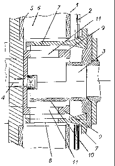
An embodiment of the invention is described with reference to the
drawing, which
shows a schematic sectional view of a blasting wheel.
The blasting wheel 1 shown in the drawing is surrounded by a housing
2, into the central section of which a feed line 3 leads by which the blasting
medium such as quartz sand or steel shot is fed to blasting wheel 1. Opposite
the mouth of feed line 3, drive shaft 4 of blasting wheel 1 protrudes from
housing 2.
Blasting wheel 1 is provided with a lateral disk 5 which is fastened to
drive shaft 4 and which on the surface opposite drive shaft 4 carries blades 6
whose inner ends adjoin a distributor sleeve 7 with a distributor opening 8.
Inside distributor sleeve 7 an impeller 9 or central accelerator non-
rotationally
connected to drive shaft 4 or lateral disk 5 is provided, which contains the
discharge openings 11. The blasting medium discharged from feed line 3 is
conveyed into impeller 9 via a grooved tongue 10 which substantially covers
the section above the distributor opening 8 in distributor sleeve 7.
3

Representative Drawing
A single figure which represents the drawing illustrating the invention.
Administrative Status

2024-08-01:As part of the Next Generation Patents (NGP) transition, the Canadian Patents Database (CPD) now contains a more detailed Event History, which replicates the Event Log of our new back-office solution.

Please note that "Inactive:" events refers to events no longer in use in our new back-office solution.

For a clearer understanding of the status of the application/patent presented on this page, the site Disclaimer , as well as the definitions for Patent , Event History , Maintenance Fee  and Payment History  should be consulted.

Event History

Description Date
Inactive: Expired (new Act pat) 2022-02-28
Common Representative Appointed 2019-10-30
Revocation of Agent Requirements Determined Compliant 2019-10-01
Appointment of Agent Requirements Determined Compliant 2019-10-01
Inactive: Office letter 2019-09-20
Revocation of Agent Request 2019-08-29
Appointment of Agent Request 2019-08-29
Grant by Issuance 2008-10-28
Inactive: Cover page published 2008-10-27
Pre-grant 2008-08-06
Inactive: Final fee received 2008-08-06
Notice of Allowance is Issued 2008-04-10
Letter Sent 2008-04-10
Inactive: Approved for allowance (AFA) 2008-01-08
Amendment Received - Voluntary Amendment 2007-09-25
Inactive: S.30(2) Rules - Examiner requisition 2007-03-26
Letter Sent 2004-11-10
Request for Examination Received 2004-10-29
Request for Examination Requirements Determined Compliant 2004-10-29
All Requirements for Examination Determined Compliant 2004-10-29
Inactive: Cover page published 2003-01-29
Inactive: Inventor deleted 2003-01-27
Inactive: Notice - National entry - No RFE 2003-01-27
Application Received - PCT 2002-11-18
Small Entity Declaration Determined Compliant 2002-10-16
National Entry Requirements Determined Compliant 2002-10-16
Application Published (Open to Public Inspection) 2002-09-12

Abandonment History

There is no abandonment history.

Maintenance Fee

The last payment was received on 2008-01-11

Note : If the full payment has not been received on or before the date indicated, a further fee may be required which may be one of the following

  • the reinstatement fee;
  • the late payment fee; or
  • additional fee to reverse deemed expiry.

Patent fees are adjusted on the 1st of January every year. The amounts above are the current amounts if received by December 31 of the current year.
Please refer to the CIPO Patent Fees web page to see all current fee amounts.

Owners on Record

Note: Records showing the ownership history in alphabetical order.

Current Owners on Record
JOST WADEPHUL
Past Owners on Record
None
Past Owners that do not appear in the "Owners on Record" listing will appear in other documentation within the application.
Documents

To view selected files, please enter reCAPTCHA code :


To view images, click a link in the Document Description column (Temporarily unavailable). To download the documents, select one or more checkboxes in the first column and then click the "Download Selected in PDF format (Zip Archive)" or the "Download Selected as Single PDF" button.

List of published and non-published patent-specific documents on the CPD .

If you have any difficulty accessing content, you can call the Client Service Centre at 1-866-997-1936 or send them an e-mail at CIPO Client Service Centre.

({010=All Documents, 020=As Filed, 030=As Open to Public Inspection, 040=At Issuance, 050=Examination, 060=Incoming Correspondence, 070=Miscellaneous, 080=Outgoing Correspondence, 090=Payment})


Document
Description 
Date
(yyyy-mm-dd) 
Number of pages   Size of Image (KB) 
Representative drawing 2002-10-15 1 36
Abstract 2002-10-15 2 77
Claims 2002-10-15 1 32
Drawings 2002-10-15 1 39
Description 2002-10-15 3 122
Claims 2007-09-24 1 29
Representative drawing 2008-10-08 1 16
Notice of National Entry 2003-01-26 1 189
Reminder of maintenance fee due 2003-10-28 1 106
Acknowledgement of Request for Examination 2004-11-09 1 177
Commissioner's Notice - Application Found Allowable 2008-04-09 1 164
PCT 2002-10-15 2 67
Fees 2003-12-08 1 27
Fees 2005-01-20 1 24
Fees 2006-02-20 1 25
Fees 2006-11-23 1 34
Fees 2008-01-10 1 26
Correspondence 2008-08-05 1 24
Courtesy - Office Letter 2019-09-19 2 36