Note: Descriptions are shown in the official language in which they were submitted.
CA 02406924 2002-10-21
WO OOI63635 ~ PCTID~00/01281
Training projectile for as automatic rapid-fire weapon
The invention relates to a medium-bore training
projectile for an automatic rapid-fire weapon and also a
system based on such a training projectile and a weapon
barrel.
For training purposes, it is necessary to have at one's
disposal training and manoeuvre ammunition, the features
of which correspond to live ammunition, at least where
rapid-fire weapons are concerned, so that all functions
can run smoothly. Tt must not be necessary in this regard
to make any essential modifications to the weapon. At the
same time, the training projectile arid any necessary
conversion kit for the weapon must be configured in such
a way that live ammunition cannot inadvertently be fired
whilst shooting with manoeuvre ammunition.
DE-A-14 53 827 proposes to equip the training cartridge
with a bore hole, which is closed off above the
propellant charge arranged in the reax area and if
necessary in the area near the projectile tip by a
destructible cap. If the cover(e) is (are) correctly
dimensioned, the projectile, When fired, is followed by
an initial shock dust, which is sufficient to guarantee a
recoil of the barrel when the weapon bolt ie reversed.
The covers are subsequently destroyed by the propellant
charge and leave the barrel before the projectile, the
speed of which 1e reduced due to the presence of the
continuous bore hole.
CA 02406924 2002-10-21
WO OO/fr31~~5 Q PCT/DE00/OIZBI
This type of training projectile however daes not
guarantee to prevent live ammunition being inadvertently
fired.
DE-A-37 33 216 discloses a weapon barrel for automatic
weapons for the purposes of firing training ammunition,
particularly blank cartridges, whereby a limiting bush is
secured near a cartridge bearing and the weapon bolt
inside the barrel and a nozzle insert is secured as a gas
choke near the muzzle in the front part of the barrel.
This limiting bush must be configured so as to prevent a
live cartridge being fully pushed into the barrel, which
ensures that the weapon will remain fully operable in
this case, Training ammunition, which is simply modified
to be thinner near the projectile tip can be inserted so
far into the limiting bush that the cartridge is
completely accommodated by the barrel.
When firing blank cartridges, this barrel, which ie
preferably a de-commissioned barrel that has been
modified for use with live ammunition, is replaced by a
barrel suitable for firing live ammunition. The use of a
nozzle insert, which if necessary has an adjustable
tuyere area, creates a gas pressure in the barrel that is
both necessary and adequate for automatic weapon function
when a training cartridge is fired. This gas pressure
guarantees both the locking function and ejection of the
cartridge. The blank cartridge does not leave the barrel,
the bang, smoke and possibly the flash from the muzzle
axe simply simulated when the blank cartridge is loaded.
This system can be applied to small-bore training
ammunition. It does however require structural
modifications to the barrel and the training ammunition.
CA 02406924 2002-10-21
WO 00/63635 3 pcTm~ooiomei
Moreover, it is very extremely difficult to achieve the
gas pressure required for medium-bore rapid-fire weapons
with this system. With conventional 4omm training
cartridges, gas pressures able to release the weapon
bolt, which. weighs approx. % kg, must be provided.
DE-A1-4134505 disclasea a small-bore cartridge for
simulated firing using a laser beam, which has a bush
with longitudinal bore hole, whereby the external form of
the bush corresponds to that of a standard cartridge case
containing a projectile. Release of a weapon bolt is also
nat possible with this cartridge.
The task of the invention is to provide a training
projectile, particularly for large-bore rapid-fire
weapons, which allows large gas pressures to be created
in the barrel LhaL can release even heavy weapon bolt. A
further purpose of a system based on this type of
training projectile and its application as a weapon
barrel is to create an automatic rapid wire weapon, which
has a reliable function, is simply constructed, consists
of few components and which is therefore coat-effective
to produce.
In terms of a training projectile, the task is solved by
the characteristics in Claim I and in terms of a system
based on a training projectile and a barrel, by the
chaxacteristics of the independent Patent Claim.
Accordingly, the training projectile has a continuous
central channel, which contains a propellant charge in
the rear area of the projectile and which is sealed off
at the rear by a detonator charge fvr the propellant
charge. The channel is open at the projectile tip.
CA 02406924 2002-10-21
WU 00/63535 q. PCT/DE0010128I
Training projectile and barrel both have devices to
prevent the insertion of a live projectile. The open
channel of the training projectile is preLerably used for
this purpose: when the training projectile is fully
inserted into the barrel, the mandrel of an insert
projects into the barrel in the open end of the channel,
whereby this insert limits the vacant apace before the
nose of the projectile. The insert can also be equipped
with overflow channels.
The mandrel ensures that a live projectile cannot be
inserted instead of a training projectile, since this is
sealed at its tip to prevent it from completely leaving
the barrel. The rapid-fire weapon would be operable in
such a case.
After the detonator charge has ignited the propellant
charge, e.g. using a strike pin, the propellant gas
disperses vehemently towards the open end of the central
channel in the training projectile, whereby a high gas
pressure is rapidly created in the relatively small space
between propellant charge and mandrel tip. This pressure
rapidly propels the projectile backwards towards the
weapon bolt which is then released.
The diameter of the insert mandrel is preferably smaller.
than the diameter clearance of the central channel in the
projectile, which creates a gap between channel and
mandrel through which the propellant gas starts to escape
shortly after the propellant charge is ignited and
through which the overflow channel in the insert acting
as a gas choke runs towards the muzzle of the barrel.
Given correct dimensions of_ the mandrel, central channel
and gas choke, the same effects as those achieved with a
CA 02406924 2002-10-21
wo ooms~s 5 rc~rm$ooioizai
live projectile can be simulated, e.g. flash, bang and
smoke.
The training projectile can essentially be constructed
from four components, namely a projectile base, a central
barrel inserted into the projectile base that rune
longitudinal to the projectile into which the propellant
charge is loaded, an ignitor cap inserted into the
projectile base for igniting the propellant charge and a
single-piece projectile body, which surrounds the central
barrel from projectile barrel upwards, this does however
leave the central barrel open at the projectile tip. The
projectile body is preferably produced from injection-
moulded plastic. The projectile base ie usually a metal
component and should preferably be aluminium or steel;
the central pipe should preferably be steel, in order to
be able to withstand the gas pressures occurring when the
propellant charge is ignited.
It is also possible, to cover the nose end of the
propellant charge with a destructible cap or rupture disk
and/or provide a further nozzle or nozzle arrangcmcnt in
the central channel, whereby the development of the gas
pressure created in the barrel can be further optimised
after the propellant charge has been ignited.
A training projectile as proposed by the invention. does
nod cause a direct pressure build up behind the training
projectile with simulated firing. Instead, the gases
created by the propellant charge are fed into the
projectile over the projectile tip, so that the qas
pressure created between the projectile tip and the
insert in the barrel propels the training projectile to
release the weapon bolt.
CA 02406924 2002-10-21
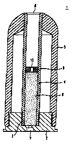
WD 00/63635 a PCTIDE00/O1Z81
The drawings help to explain the invention in more
detail. These drawings show:
Figure 1: a cut view of a training projectile fox a
40 mm rapid-fire weapon as proposed by the
invention
Figures 2 to 6: sequential drawings showing simulated
firing of a training projectile, from
loading the projectile through to ejection
and
Figure 7: a partially cut view of a slightly
modified training projectile
Ae shown by b'igure 1, training projectile 1 has a
projectile base 2 from aluminium, a central steel barrel
4 screwed into a central thread 3 of the projecl:ile base
and a projectile body 5 forming a cup shape from the
projectile base upwards, this projectile body being a
single-piece injection-moulded plastic component and
extending to the front end of the steel barrel 4. The rear
half of the steel barrel 4 is filled with propellant
charge 6, which, with the aid of a striking pin, can be
ignited by an ignitor cap 7 inserted into the projectile
base in the rear of the projectile. The steel, barrel has
at its tip a free opening 8, the edge of which lies
directly adjacent to the aforementioned projectile body
5.
As shown by Figure 1, central steel barrel 4 can be split
at its centre by a dividing wall 9, in which a nozzle l0
is provided, which connects the space around propellant
CA 02406924 2002-10-21
wo oom363s 7 pcTm~aoiamsi
charge 6 with the empty space in the steel barrel up to
opening 8.
Tn Figure 2, 21 shows a barrel of an automatic rapid-fire
weapon, for which no further drawings exist. An insert 22
is pushed into this barrel from the front end outwards,
whereby this insert consists of a barrel 23 and a piston
24, Barrel 23 lies flush with the inside of barrel 21 and
is fitted at the end facing piston z4 with a limit stop
25, which lies adjacent to the front edge of barrel 21.
Barrel 23 is held by a spigot nut 26 with a central
opening 27, which is screwed into an outer thread of
barrel 21.
Piston 24 has a central mandrel 28, the outer diameter of
which is smaller than the clear diameter of steel barrel
4. The length of the mandrel is equivalent to a maximum
of the distance between opening 8 of the steel barrel 4
and the dividing wall 9 in barrel 4.
Several further overflow channels 29 are provided around
central mandrel z8 in piston 24.
Figures 2 to 7 show the functional sequence of the
automatic rapid-fire weapon when used with the training
projer_tile.
Figure 2 shows the point in time at which training
projectile 1 is loaded by the bolt in barrel 21: this
process causes central mandrel 28 of insert 22 to project
into central steel barrel 4.
In Figuxe 3, training projectile 1 has completely left
the lock and is located in barrel 21; at this moment in
CA 02406924 2002-10-21
wo oomr~s g rcTmEOOroiisi
time, ignitor cap 7 is ignited by a strike pan of the
Lock. The propellant charge 6 is ignited at virtually the
same time.
The propellant gases (31) generated as the charge ie
combusted, which are schematically illustrated in Figure
4, dzspex~ss towards the projectile nose, wheyeby the gas
is choked through the gap between central mandrel 2d and
the width clearance of central barrel 4. The gases flow
into the space that forms a vacant space 30 between the
front end of a propellant charge and the tip of the
mandrel; this creates a high gas pressure, which, as
indicated in Figure 4 by the arrow, moves the projectile
back towards the lock.
The propellant gases. the volume of which has increased
in vacant space 30 between the projectile nose and piston
24, escape from free opening a of the steel barrel and
through the gap between mandrel Z8 and steel barrel 4, so
that the pressure of these propellant gases, as indicated
in Figure 5, now acts on the full face of the projectile
and accelerates this backwards into the projectile. The
propellant gases then flow through overflow channels 29
and escape into the outside air from central opening 27
of spigot nut 26.
At the point in time indicated in Figure 6, the training
projectile slides completely from central mandrel 28 and
is transferred back into the bolt, from which point it is
subsequently ejected.
Hy optimising the dimensions of mandrel diameter 28,
diameter clearance of eteei barrel 4, number and diameter
of overflow channels 29 and the distance between piston
CA 02406924 2002-10-21
WO 00/63635 9 PCTIDE00/01181
24 and insert 22 and where necessary arranging and
dimensioning nozzle 10 in dividing wall 9, the pressure
build-up in barrel 21 can be optimised to force the
training projectile back into the bolt. The gas pressure
created initially in a small high pressure space between
propellant charge and mandrel tip and the subsequent
creation of another pressure area between the piston and
the entire cross-sectional area of the projectile, the
high forces required for the bolt of the automatic weapon
to function are achieved. It is also possible, through
the stated dimensioning and also of course collecting the
propellant charge at the muzzle of barrel 21 for
simulated firing, to imitate the effects occurring with
live ammunition, e.g. flashes, bangs and smoke.
Figure 7 shows a modified training projectile. For
equivalent elements as illustrated by the design example
in Figure 1, equivalent reference symbols are used. With
this projectile, propellant charge 6 positioned on the
rear side is covered by a destructible cap or rupture
disk 71; the dividing wall with nozzle is omitted. The
diameter of the training shot reduces in the none area,
so that a limit stop 72 is created, which then lies
adjacent to a corresponding limit stop 73 of the barrel
21 indicated schematically here. In this nose area of the
projectile, the diameter of the barrel is smaller than in
the rear area of the projectile. Live ammunition, the
diameter of which is the same in both the nose and the
rear area, cannot be inserted into this barrel.
The firing functions are the same as described above; the
mandrel, which in the above design ie inserted into
channel 8, is not required with this design. However, it
is possible to uee both mandrel and limit stop jointly.
CA 02406924 2002-10-21
WO 00/63635 10 PCTln1C00/01281
It is also possible, to provide a proprietary training
barrel rather than modifying a barrel intended for live
ammunition by adding an insert. IL Llashes, smokes and
bangs are not simulated, the aforementioned overflow
channels in the gae choke can also be omitted, so that
all the gas pressure is used to drive back the projectile
and release the weapon bolt.