Note: Descriptions are shown in the official language in which they were submitted.
CA 02407359 2002-10-21
WO 01/81685 PCT/US00/29810
OPEN WEB DISSYMMETRIC BEAM CONSTRUCTION
BACKGROUND OF THE INVENTION
The present irwention relates to the construction of multi-story
buildings, and more particularly to an improved composite structural framing
system and associated method of construction wherein concrete plank
sections are assembled and grouted about a specially adapted open web
dissymmetric steel beam having a plurality of openings made through the web
of the beam along the length thereof to improve grout flow through and about
the beam so that the resulting concrete encasement of the beam develops
greater composite action and structural integrity in the system.
In the Meld of building construction, particularly in those buildings of
multiple stories, the framing system provides the essential load bearing
element that characterizes and determines the load carrying capacity and
structural integrity of the building. Designed to comply with standard
building code requirements, the framing systems of modern multi-story
buildings are generally made of heavy, flre-resistive materials, such as
structural steel and concrete. Typically consisting of a plurality of vertical
steel columns and horizontal steel beams extending between and connected to
each column, the standard framing system further includes floors of
reinforced concrete that may be precast or cast-in place supported by and
between the horizontal beams on each level. While each framing system must
be designed to safely carry all of the anticipated vertical loads affecting
the
building and provide stabilization against lateral loads caused by wind or
other horizontal forces, it is important that the system be easy to assemble
and
1
CA 02407359 2002-10-21
WO 01/81685 PCT/US00/29810
cost-effective as well in order to afford its use in modern construction
projects.
In recent years, revisions to the national and international building code
standards, particularly those model provisions of the Building Officials and
Code Administrators international, Inc. (BOCA), have increased lateral load
requirements for seismic design criteria, especially affecting multi-story
building constluiction. As a result, the framing systems of most prospective
multi-story building st~aictures will be required to resist lateral loads
greater
than those able to be accommodated by much of the existing structural
framework incorporated into building construction over the last few decades.
Because of the increased seismic design criteria and the continuing pressure
of minimizing construction costs, new design alternatives for structural
framing systems have been developed in order to meet all of the current
loading requirements imposed upon modern mufti-story buildings in an
economical and cost-effective manner.
One recent design alternative for a structural framing system is
described in U. S. Patent No. 5,704,181 wherein a dissymmetric steel beam
having a compressed, block-like top flange, a flattened bottom flange, and a
continuous solid web integrally extending therebetween is adapted to be
horizontally disposed between adjacent vertical steel columns that are erected
upon conventional foundations. Standard hollow core sections of precast,
prestressed concrete plank are then installed along either side of the
dissymmetric beam supported upon the bottom flange and together assembled
so that the beam is disposed centrally between facing edges of the plank
sections all in substantially the same horizontal plane. Grouting of the
assembled beam and plank sections then provides encasement of the beam,
2
CA 02407359 2002-10-21
WO 01/81685 PCT/US00/29810
interlocking the beam and plank sections and developing a composite action
that enhances the loadbearing capacity of the system. While the framing
system of the aforementioned patent has performed satisfactorily and
produced increased loadbearing results in testing that are indicative of the
development of composite action between the steel beam and the concrete
plank, further testing has indicated a need to guarantee a more homogeneous
and uniform bond between the structural steel and the precast concrete in
order to ensure the maintenance of the interlocking effect and the composite
action initially developed by the aforedescribed framing system.
3
CA 02407359 2002-10-21
WO 01/81685 PCT/US00/29810
SUMMARY OF THE INVENTION
Accordingly, it is a general purpose and object of the present' invention
to provide an improved structural framing system and associated method of
construction that increases the structural integrity and load carrying
characteristics of mufti-story buildings.
A fiirther object of the present invention is to provide a structural
framing system and method of constructing same that provides a more
effective and economical means for supporting the loading requirements of
modern-day building structures, particularly those having multiple stories,
than those structural framing systems heretofore developed.
A more specific object of the present invention is to provide an
improved composite assembly of structural elements in a framing system for
mufti-story construction that is capable of handling all the loading
requirements now specified under applicable building codes, including those
lateral load requirements associated with potential seismic activity, within a
minimum building elevation, and adapted to better maintain its composite
strength and structural integrity over the useful life of the construction.
A still further object of the present invention is to provide a safe and
effective structural framing system that may be assembled and implemented
using relatively standard construction materials and equipment.
Briefly, these and other objects of the present invention are
accomplished by an improved structural framing system and associated
method of construction wherein an open web dissymmetric steel beam
fabricated having a phlrality of trapezoidal openings formed along the web
thereof between a narrowed, thickened top flange and a widened bottom
4
CA 02407359 2002-10-21
WO 01/81685 PCT/US00/29810
flange is horizontally disposed and supported between adjacent . vertical
columns erected on conventional foundations. The dissymmetric beam is
preferably fabricated from a standard rolled, wide flange beam split
longitudinally according to a specific cutting pattern to produce
substantially
identical open web beam sections having a single wide flange. A flat bar
plate is then welded along the open web beam section to provide the top
flange and thereby produce the dissymmetric beam for use in the present
system. Standard hollow core sections of precast concrete plank are
assembled together perpendicularly to the open web dissymmetric beam and
supported upon the bottom flange on either side thereof so that the open web
of the beam is centrally disposed between end surfaces of the plank sections
in substantially the same horizontal plane. A high-strength grout mixture
applied to the assembled beam and plank sections is made to flow completely
through the web openings in a circulatory manner thereby creating a
substantially monolithic concrete encasement around the dissymmetric beam
that improves the resulting composite action and mechanical interlock
between the steel beam and concrete plank and prevents loss of strength due
to separation of the grout from either side of the beam.
For a better understanding of these and other aspects of the present
invention, reference may be made to the following detailed description taken
in conjunction with the accompanying drawing in which like reference
numerals designate like parts throughout the figures thereof.
CA 02407359 2002-10-21
WO 01/81685 PCT/US00/29810
BRIEF DESCRIPTION OF THE DRAWINGS
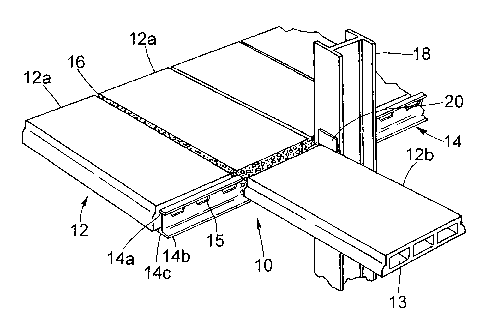
FIG. 1 is a fragmentary perspective view of the structural framing
system assembled and constructed in accordance with the present invention;
FIG. 2 is a front elevational view of the assembled structural framing
system of FIG. 1 shown partially cross-sectioned;
FIG. 3 is a side elevation view of the open-web dissymmetric beam
used in present structural framing system and shown apart therefrom in
substantially the horizontal attitude in Which the beam is supported within
the
system of the present invention; and
FIG. 4 is a cross-sectional view of the open-web dissymmetric beam
taken along the line 4-4 in FIG. 3; and
FIG. 5 is a diagrammatic representation of the continuous cutting
pattern employed to obtain the open-web dissymmetric beam of FIGS. 3 and
4 for use in the present invention.
6
CA 02407359 2002-10-21
WO 01/81685 PCT/US00/29810
DESCRIPTION OF THE PREFERRED EMBODIMENT
Referring now to the drawings and in particular at first to FIGS.1 and 2,
a structural framing system, generally designated 10, is shown constructed in
accordance with the present invention. The framing system 10 incorporates a
series of concrete plank sections, generally designated 12, installed in
successive pairs 12a, 12b and joined together along either side of a specially-
configured steel dissymmetric beam 14 using a high-strength grout material
16, both described in greater detail hereinbelow. The plank sections 12a, 12b
extend outward from the dissymmetric beam 14 and together span
horizontally between adjacent vertical columns 18 that are fabricated of a
structural steel material and erected on conventional foundations. As
described in greater detail below, each dissymmetric beam I4 has a distinct
top and bottom flange, 14a and 14b respectively, and an open web 14c
extending longitudinally therebetween. In accordance with the present
invention, each open web dissymmetric beam 14 is horizontally disposed and
connected between the adjacent vertical columns 18 by conventional welding
means further supported, as necessary, with standard beam-to-column
connections secured to each vertical column.
The plank sections 12a, 12b are conventional precast and prestressed
concrete members each typically formed having a series of hollow cores 13
extending transversely therethrough. Solid plank members without cores 13
may also be used in the present structural framing system 10 as plank sections
12a, 12b provided the end surfaces thereof are prepared with indentations
therein as described below. The plank sections 12a, 12b ' installed in any
specific structural framing system 10 are formed to have a substantially
7
CA 02407359 2002-10-21
WO 01/81685 PCT/US00/29810
uniform thickness which may range from 6 to I2 inches between the upper
and lower surfaces of the plank depending upon the specific design criteria
associated with the particular construction. The end surfaces of each plank
section 12, particularly those facing ends intended to be joined about the
dissymmetric beam 14,, are formed substantially perpendicular to the upper
and lower plank surfaces to permit the respective pairs of plank sections 12a,
12b to be squarely placed and supported along either side of the dissymmetric
beam with the plank'sections and beam being disposed in substantially the
same horizontal plane.
As better viewed in FIG. 2, the proximal end surfaces of the opposed
plank sections 12a, 12b are similarly placed on each side of the dissymmetric
beam 14 in juxtaposition therewith, particularly -abutting the top flange 14a
and bearing upon the bottom flange 14b, to provide an encasement area
therebetween for the application and deposit of the high-strength grout
material 16 at the time of joinder to the beam. In the case of the use of a
solid
plank member, the ends of the opposed plank sections I2a, 12b should have
indentations formed along their edge surfaces to provide the same form of
encasement area along either side of the open web dissymmetric beam 14. A
conventional mixture of mortar or like cement material, the grout 16 is made
having a strength rated in the range of 3,000-8,000 psi and is preferably
premixed for application along the length of the dissymmetric beam 14 and
between the assembled plank sections I2a, I2b so that the grout may flow
through the beam and fill the encasement area in a manner described below in
greater detail. Standard core plugs (not shown) generally round in
configuration may be inserted into the hollow core 13 of each plank section
12a, 12b along their respective end surfaces to laterally confine and limit
the
s
CA 02407359 2002-10-21
WO 01/81685 PCT/US00/29810
encasement cavity and prevent the unnecessary flow of the grout material 16
away from the intended joint area immediately about the dissymmetric beam
14. Other types and forms of material suitable to dam the hollow cope 13 near
the ends of the plank sections 12a, 12b may also be used to limit the
encasement area and confine the flow of grout material 16.
Referring now to FIGS. 3~5 in conjunction with FIGS. 1 and 2, the
dissymmetric beam 14 of the present structural framing system 10 is specially
fabricated to provide its open wpb 14c along the complete span of the beam
between top flange 14a and bottom flange 14b. A plurality of openings 15 are
provided along the upper edge of web 14c just beneath top flange 14a, each
opening being similarly shaded having a substantially trapezoidal
configuration, as best shown in FIG. 3. Adjacent openings 15 are
equidistantly spaced apart along the length of the dissymmetric beam 14 with
those openings located nearest to the far ends of the web 14c being spaced
sufficiently from each respective end so that a solid web section is provided
at
either end of the beam between tlxe top flange 14a and bottom flange 14b for
more effective attachment to the vertical columns l~. The width of each
opening 15 at the upper edge of web 14c and tlxe spacing therealong between
adjacent openings are substantially~the same dimension and may be varied to
alter the number and an angement of openings depending upon the particular
building construction and associated Ioad requirements placed upon the
stnictural framing system 10. The depth of each opening 15 may also vary in
its dimension but generally extends tlxrough the centerline of the web 14c.
Alternate rectilinear configurations or curvilinear slxapes for the openings 1
S
made in web 14c may be equally suitable for incorporation in the
dissymmetric beam 14 of the present invention provided that the respective
9
CA 02407359 2002-10-21
WO 01/81685 PCT/US00/29810
configuration and number of such alternate openings do not compromise the
structural integrity of the dissymmetric beam 14.
The present dissymmetric beam 14, particularly the open ~ web 14c
described above, is preferably made by cutting a standard rolled, wide flange
structural steel beam, one such example being commonly known and
commercially available as a W10x49 member. In this preferred method of
fabricating the present dissymmetric beam 14, the standard rolled beam is cut
through the entire length of its web according to a specific cutting pattern P
intended to split the initial beam into separate wide flange beam sections 21
each with the plurality of openings 1 S described above produced therein. As
best viewed in FIG. S, the cutting pattern P used to produce the plurality of
openings 1 S in the web 14c of dissymmetric beam 14 is a repetitive series of
connected linear segments made on alternating levels upward and downward
along the web of the standard beam. Appearing as a periodic rectilinear wave
form spanning from one end of the beam to the other, the cutting pattern P is
made of an upper horizontal segment 22, a downwardly and forwardly angled
segment 24, a lower horizontal segment 26 and an upwardly and forwardly
angled segment 28, repeated along the length of the beam symmetrically
about the centerline thereof. Other periodic cutting patterns having similar
alternating levels of either linear or curvilinear segments may be used in
accordance with the present invention to split the standard beam into
respective sections 21 having web openings in different geometric
configurations suitable for the present structural framing system 10. Cutting
of the standard rolled beam as aforedescribed may be accomplished by
conventional flame cutting or mechanical means that may be in a semi-
automatic or automatic assembly programmable to produce the specific
CA 02407359 2002-10-21
WO 01/81685 PCT/US00/29810
cutting pattern. Alternatively, the open web dissymetric beam 14 of the
present invention may be fabricated from separate plate members,
respectively corresponding to the top flange 14a, bottom flange 14b' and open
web 14c, assembled together and welded in the dissymetric form described
using conventional yvelding techniques in accordance with AISC or
equivalent standards. In either method of fabrication of the open web
dissymmetric beam 14, it should be understood that the web openings 15 be
spaced apart along the entire length of the beam beneath the top flange 14a to
promote optimal flow of the grout material 16 through and along the beam
within the encasement area when constructing the structural framing system
10.
In the preferred method of fabrication described above in reference to
FIG. 5, the respective beam sections 21 produced by the cutting pattern P are
each separately employed and processed to produce the open-web
dissymmetric beam 14 for use in the present structural framing system 10. To
produce a single dissymmetric beam 14, a respective one of the beam sections
21 is combined with a length of flat bar plate made of structural steel
material
that is positioned across the top of the openings 15 along the entire length
of
the beam section in parallel alignment with the bottom flange 14b. Formed
having a narrower width, typically in the range of 2-4 inches, and a greater
thickness than corresponding dimensions of the bottom flange 14b, the length
of bar plate is then welded to and across the open web 14c by fillet welding
in
accordance with AISC or equivalent standards. The resultant product is the
open web dissymmetric beam 14 made in accordance with the present
invention having its narrow, thickened top flange 14a disposed across and
along the open web 14c substantially parallel to and aligned with the wide
11
CA 02407359 2002-10-21
WO 01/81685 PCT/US00/29810
bottom flange 14b. The longitudinal profile of the open web 14c, best viewed
in FIG. 3, reflects the resultant dissymmetric .beam 14 having the series of
trapezoidal openings 15 formed along the upper edge of the web throughout
its length, the open web and its openings thus formed to provide routing for
the free flow of grout 16 in a circulatory manner through the dissymmetric
beam 14 upon its application to the assembled structural framing system 10 of
the present invention. Prior to its placement and assembly in the framing
system 10, the dissymmetric beam 14 may be further provided with solid web
plates 20 welded to the beam at both ends for reinforcement of the beam
member and support in its attachment to the vertical columns 18.
In constructing the present structural framing system 10, the open web
dissymmetric beam 14 is lifted to a specific elevation and secured in a
substantially horizontal position between adjacent vertical columns 18. Each
dissymmetric beam 14 is attached to the corresponding vertical column 18
using standard end plate connections or other equivalent means for making
the structural attachment. thereto. With the dissymmetric beam 14 secured in
such position having top flange 14a directed upwardly, the plank sections 12a,
12b are installed and assembled in pairs upon either side of the dissymmetric
beam. Each plank section 12a, 12b is positioned alongside the dissymmetric
beam 14 spanning outwardly therefrom in substantially the same horizontal
plane as the beam and its open web 14c. Facing edges of the plank sections
12a, 12b are brought together to immediately abut the dissymmetric beam 14
so that the open web 14c of the beam is centrally disposed between the edges
with the bottom flange 14b supporting the lower surfaces of the respective
plank sections. In this position with the edges of the plank sections 12a, 12b
bearing upon the bottom flange 14b of the beam 14 and the plank sections in
I2
CA 02407359 2002-10-21
WO 01/81685 PCT/US00/29810
horizontal planar alignment, the upper surface of the top flange 14a is
substantially level with the upper surface of the plank sections, as best
viewed
in FIG. 2.
The described assembly of the horizontally spanning plank sections
12a, 12b and centrally disposed dissymmetric beam 14 is structurally joined
together by the controlled application of grout 16 along the beam and into the
encasement area formed by facing edges of the plank sections at and along
their bearing on the open web dissymmetric beam. The grout material 16 is
typically applied by pouring the material along the top flange 14a on either
side of the dissymmetric beam 14 in sufficient amount to fill the encasement
area around the beam. The grout material 16 is permitted to flow along and
through the open web 14c from either side of the dissymmetric beam I4 in a
circulating fashion routed via the plurality of openings 15 so that a more
uniform and homogenous distribution of the grout results in the encasement
area. Upon setting of the grout material 16 around the open web
dissymmetric beam 14, a more solid and substantially monolithic concrete
encasement is thus produced that enhances the effect of composite action
developed in the framing system 10 and, as a ful-ther result, improves the
overall structural integrity of the system. Load testing and evaluation of the
constructed framing system 10 assembled with the open web dissymmetric
beam 14 indicates a more monolithic concrete encasement and greater
adherence between the steel and concrete materials, particularly in the
encasement area around the interior of the beam. This increased monolithic
quality and adherence effect in the concrete encasement area reduce the risk
of composite failure and separation of the concrete around the beam and
13
CA 02407359 2002-10-21
WO 01/81685 PCT/US00/29810
without the need for additional mechanical connections between the beam
web and the grout.
Adjacent pairs of plank sections 12a, 12b are further installed and
assembled together in a similar fashion at or about substantially the same
time
so that the grouting of the assembled pairs of plank along the open web
y
dissymmetric beam 14 and between adjacent plank sections can proceed in a
relative continuous operation. The process of installation and assembly of the
plank sections 12a, 12b along the dissymmetric beam and the grouting thereof
continues throughout the story level between all vertical columns and is
repeated for each story of the construction.
The disclosed construction and assembly of the structural framing
system 10 produces an improved composite action between the open web
dissymmetric beam 14 and the plank sections 12a, 12b that significantly and
unexpectedly increases the loadbearing capacity of the system far beyond that
of the beam alone. The composite action of the present structural framing
system 10, produced without use of shear connectors typically found atop
steel beams in existing composite structures, is the result of enhanced
mechanical interlocking and concrete encasement of the specially configured
open web dissymmetric beam 14 secured centrally between the plank sections
12a, 12b and perpendicular to the span thereof. The composite action
developed in the present framing system 10 by the improved mechanical
interlocking of its structural elements contributes substantially to a
determined increase in loadbearing capacity of the system ~ that approximates
twice that of the dissymmetric beam 14 itself. The combination of the open
web dissymmetric beam 14 and the grouted plank sections 12a, 12b of the
present structural framing system 10 further evidences a strengthening effect
14
CA 02407359 2002-10-21
WO 01/81685 PCT/US00/29810
with respect to the structural integrity of the composite joint .and the
maintenance of the composite action over time.
Therefore, it is apparent that the disclosed invention provides an
improved structural framing system and associated method of construction
that produces a significant and unexpected increase in the composite action
developed within the structural assembly, resulting in a substantial
improvement in the structural integrity, strength and serviceability of the
associated building in which the present system is employed. The present
structural framing system provides a more cost effective and reliable means
for supporting the Ioad requirements of modern-day building structures,
particularly those having multiple stories, than the structural framing
systems
heretofore developed. The present invention further provides an improved
composite assembly of structural elements for framing multi-story
constmtction that is more capable of handling all of the loading requirements
now specified under standard building codes, including those lateral load
requirements associated with potential seismic activity, within a minimum
building elevation, and adapted to better maintain its composite strength and
structural integrity over the useful life of the construction. In addition,
the
present invention provides a safe and effective structural framing system that
can be assembled and implemented using relatively standard construction
materials and equipment.
Obviously,_ other embodiments and modifications of the present
invention will readily come to those of ordinary skill in the art having the
benefit of the teachings presented in the foregoing description and drawings.
For example, solid and reinforced concrete slab members could be used
instead of the hollow core plank sections 12a, 12b, as previously indicated,
CA 02407359 2002-10-21
WO 01/81685 PCT/US00/29810
with proper preparation of their respective end surfaces. Further, the depth
or
height of the open web 14c and corresponding dimension of the opening 15
therein may be varied depending upon the thickness of the plank sections
12a,12b employed, and particulaxly may be increased in size to level and
accommodate a layer of cementitious topping that may be applied over top of
the plank sections in certain building constructions. It is therefore to be
understood that various changes in the details, materials, steps and
arrangement of parts, which have been described and illustrated to explain the
nature of the present invention, may be made by those skilled in the art
within
the principles and scope of the invention as expressed in the appended claims.
16