Language selection

Search

Patent 2407554 Summary

Third-party information liability

Some of the information on this Web page has been provided by external sources. The Government of Canada is not responsible for the accuracy, reliability or currency of the information supplied by external sources. Users wishing to rely upon this information should consult directly with the source of the information. Content provided by external sources is not subject to official languages, privacy and accessibility requirements.

Claims and Abstract availability

Any discrepancies in the text and image of the Claims and Abstract are due to differing posting times. Text of the Claims and Abstract are posted:

  • At the time the application is open to public inspection;
  • At the time of issue of the patent (grant).
(12) Patent: (11) CA 2407554
(54) English Title: METHOD AND APPARATUS FOR DESANDING WELLHEAD PRODUCTION
(54) French Title: METHODE ET APPAREIL DE DESENSABLEMENT POUR LA PRODUCTION A LA TETE DE PUITS
Status: Term Expired - Post Grant Beyond Limit
Bibliographic Data
(51) International Patent Classification (IPC):
  • B01D 45/02 (2006.01)
  • E21B 43/08 (2006.01)
  • E21B 43/12 (2006.01)
  • E21B 43/34 (2006.01)
(72) Inventors :
  • PRICE, KEVIN D. (Canada)
  • HEMSTOCK, CHRISTOPHER A. (Canada)
  • BERKAN, BRUCE G. (Canada)
(73) Owners :
  • SPECIALIZED DESANDERS INC.
(71) Applicants :
  • SPECIALIZED DESANDERS INC. (Canada)
(74) Agent: PARLEE MCLAWS LLP
(74) Associate agent:
(45) Issued: 2006-06-20
(22) Filed Date: 2002-10-10
(41) Open to Public Inspection: 2004-04-10
Examination requested: 2005-04-01
Availability of licence: N/A
Dedicated to the Public: N/A
(25) Language of filing: English

Patent Cooperation Treaty (PCT): No

(30) Application Priority Data: None

Abstracts

English Abstract

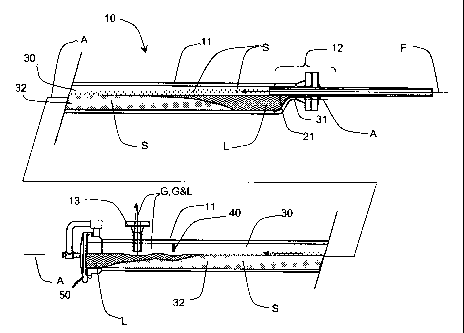
A desanding vessel is connected to a fluid stream containing entrained particulates flowing from a wellhead. The vessel comprises an upper freeboard volume wherein the fluid velocity drops and particulates fall from suspension. Preferably the fluid stream is introduced offset upwardly from an axis of a horizontally-oriented cylindrical vessel, released particulates falling to accumulate in a lower belly portion. The freeboard volume is maintained using a depending flow barrier spaced from the fluid inlet and adjacent the vessel's outlet. A cleanout enables periodic removal of accumulations.


French Abstract

Un récipient de dessablage est connecté à un courant liquide contenant des particules entraînées s'écoulant d'une tête de puits. Le récipient comprend un volume d'espace libre supérieur où la vitesse du fluide diminue et les particules tombent en suspension. De préférence, le courant liquide est introduit en décalage vers le haut par rapport à un axe d'un récipient cylindrique orienté horizontalement, les particules libérées tombant pour s'accumuler dans une partie inférieure du ventre. Le volume d'espace libre est maintenu à l'aide d'une barrière d'écoulement espacée de l'entrée du liquide et à côté de la sortie du récipient. Un nettoyage permet le retrait périodique des accumulations.

Claims

Note: Claims are shown in the official language in which they were submitted.


THE EMBODIMENTS OF THE INVENTION FOR WHICH AN
EXCLUSIVE PROPERTY OR PRIVILEGE IS CLAIMED ARE DEFINED AS
FOLLOWS:
1. A desanding vessel for removing particulates in a fluid
stream, comprising:
a fluid inlet adjacent a first end of the vessel and adapted for
receiving the fluid stream, the fluid inlet discharging the fluid stream at an
inlet
velocity into a freeboard portion at a top of the vessel, the fluid stream in
the
freeboard portion having a cross-sectional area greater than that of the inlet
for
creating a freeboard velocity less than the inlet velocity such that contained
particulates fall out of suspension;
a fluid outlet from the vessel, the fluid outlet being spaced
horizontally from the fluid inlet; and
a flow barrier, depending from the top of the vessel and having a
lower edge so as to direct the fluid stream below the flow barrier before the
fluid
stream discharges from the fluid outlet for maintaining the freeboard portion
and
forming a belly storage portion therebelow, the flow barrier further being
positioned between the fluid inlet and fluid outlet and spaced from the fluid
inlet
so as to cause accumulation of particulates in the belly portion prior to the
flow
barrier.
2. The desanding vessel of claim 1 wherein the flow barrier is a
downcomer weir.
7

3. The desanding vessel of claim 1 or 2 wherein the vessel is
cylindrical having a substantially horizontal axis.
4. The desanding vessel of claim 1 or 2 wherein the vessel is
cylindrical having a substantially horizontal axis extending substantially the
length
of said vessel wherein the fluid inlet discharges the fluid stream into the
freeboard
portion of said vessel via an inwardly extending fluid introduction means.
5. The desanding vessel of claim 4 wherein the fluid inlet
discharges the fluid stream into the freeboard portion via said fluid
introduction
means along a fluid path which is substantially parallel to the axis.
6. The desanding vessel of claim 5 wherein the fluid inlet is
offset above the axis of said vessel.
7. The desanding vessel of any one of claims 4 - 6 wherein the
fluid inlet comprises an eccentric fitting for aligning said fluid
introduction means
offset from and above said axis, so that fluid is introduced into the vessel
above
said axis.
8. The desanding vessel of any one of claims 1 - 7 further
comprising a cleanout port for periodically accessing and removing said
particulates accumulated in the belly portion.
8

9. The desanding vessel of claim 8 further comprising:
means for de-pressurizing the vessel before opening the cleanout
port.
10. A substantially elongate, horizontal vessel for removal of
particulates entrained in a fluid stream emanating from a petroleum well,
comprising:
a fluid inlet adjacent a first end of the vessel, adapted for receiving
the fluid stream and discharging the fluid steam at an inlet velocity into an
upper
region of said vessel, such vessel having a greater cross-sectional area than
said
fluid inlet such that said fluid stream entering said vessel slows to a
velocity less
than said inlet velocity and particulates fall out of suspension and collect
on a
lower region of said vessel;
a fluid outlet from the vessel, positioned in the upper region of said
vessel for directing said fluid stream having particulates substantially
removed
therefrom from the vessel;
a flow barrier, positioned in a path of flow of said fluid stream from
said fluid inlet to said fluid outlet, said flow barrier directing the path of
flow of said
fluid stream thereunder; and
a belly portion for accumulating said particulates prior to said flow
barrier.
11. The vessel of claim 10 wherein the flow barrier is a
downcomer weir for maintaining the upper region of said vessel.
9

12. The desanding vessel of claim 10 or 11 wherein the vessel is
cylindrical having a substantially horizontal axis.
13. The vessel of claim 11 or 12 wherein the vessel is cylindrical
having a substantially horizontal axis extending substantially the length of
said
vessel wherein the fluid inlet discharges the fluid stream into the upper
portion of
said vessel via an inwardly extending fluid introduction means.
14. The vessel of claim 13 wherein the inlet discharges the fluid
stream into the upper portion via said fluid introduction means along a fluid
path
which is substantially parallel to the axis.
15. The vessel of claim 14 wherein the fluid inlet is offset above
the axis of said vessel.
16. The vessel of any one of claims 13 - 15 wherein the fluid inlet
comprises an eccentric fitting for aligning said fluid introduction means
offset from
and above said axis, so that fluid is introduced into the vessel above said
axis.
17. The vessel of any one of claims 10 - 16 further comprising a
cleanout port for periodically accessing and removing particles accumulated in
the belly portion.
18. The vessel of claim 17 further comprising means for de-
pressurizing the vessel before opening the cleanout port.
10

19. A substantially elongate, horizontal vessel for removal of
particulates entrained in a fluid stream emanating from a petroleum well,
comprising:
an upper region;
a lower belly region;
a fluid inlet adjacent a first end of the vessel, adapted for receiving
the fluid stream having an inlet velocity and discharging the fluid stream
into said
upper region of said vessel, said upper region having a greater cross-
sectional
area than said fluid inlet such that said fluid stream slows to a velocity
less than
said inlet velocity and particulates fall out of suspension and collect on
said lower
belly region of said vessel;
a fluid outlet from the vessel, spaced horizontally from the fluid inlet
and situated proximate a second opposite end of said vessel, positioned in
said
upper region of said vessel; and
a flow barrier extending downwardly through said upper region so
as to direct the fluid stream below the flow barrier before the fluid stream
discharges from the fluid outlet, the flow barrier being positioned between
the
fluid inlet and fluid outlet and spaced from the fluid inlet to permit
accumulation of
said particulates in said lower belly region prior to the flow barrier.
20. The vessel of claim 19 wherein the flow barrier is a
downcomer weir.
21. The vessel of claim 19 or 20 wherein the vessel is cylindrical
having a substantially horizontal axis.
11

22. The vessel of claims 19 or 20 wherein the vessel is
cylindrical having a substantially horizontal axis extending substantially the
length
of said vessel wherein the fluid inlet discharges the fluid stream into the
upper
portion of said vessel via an inwardly extending fluid introduction means.
23. The vessel of claim 22 wherein inlet discharges the fluid
stream into the upper region via said fluid introduction means along a fluid
path
which is substantially parallel to the axis.
24. The vessel of claim 23 wherein the fluid inlet is offset above
the axis of said vessel.
25. The vessel of any one of claims 22 - 24 wherein the fluid inlet
comprises an eccentric fitting for aligning said fluid introduction means
offset from
and above said axis, so that fluid is introduced into the vessel above said
axis.
26. The vessel of any one of claims 20 - 25 further comprising a
cleanout port for periodically accessing and removing said particulates
accumulated in the belly portion.
27. The vessel of claim 26 further comprising means for de-
pressurizing the vessel before opening the cleanout port.
12

28. A system for removing particulates entrained in a fluid
stream emanating from a petroleum well, comprising:
a substantially elongate, horizontal pressure vessel , comprising:
(i) an upper region;
(ii) a lower belly region;
(iii) a fluid inlet situated proximate a first end of said vessel
and the upper region thereof, adapted for receiving said fluid stream having
an
inlet velocity and discharging the fluid stream into said upper region of said
vessel, said upper region having a greater cross-sectional area than said
fluid
inlet such that said fluid stream slows to a velocity less than said inlet
velocity
and particulates fall out of suspension and collect in said lower belly region
of
said vessel;
(iv) a fluid outlet from the vessel, situated at a second end of
said vessel opposite said first end;
(v) a flow barrier, extending downwardly through said upper
region and situated proximate said fluid outlet so as to direct the fluid
stream
below the flow barrier immediately before the fluid stream travels upwardly
and
discharges from the fluid outlet, positioned between the fluid inlet and fluid
outlet
and spaced from the fluid inlet to permit accumulation of said particulates in
said
lower belly region;
(vi) a clean-out port proximate said second end, to permit
access to said vessel to remove particulates collected in said belly region
during
a cleaning step;
(vii) means for depressurizing said vessel during said
cleaning step; and
13

an inlet flow valve, situated proximate said fluid inlet on said
pressure vessel; and
an outlet flow valve, situated proximate said fluid outlet on said
pressure vessel.
29. The system for removing particulates as claimed in claim 28,
wherein said fluid inlet discharges said fluid stream into said vessel along
substantially a horizontal longitudinal axis of said vessel.
14

30. A method for removing particulates contained in a fluid
stream flowing from an existing wellhead, comprising:
receiving the fluid stream at a fluid inlet, the fluid stream being
discharged therefrom to a freeboard portion at a top of a vessel, the fluid
stream
in the freeboard portion having a freeboard velocity less than an inlet
velocity of
said fluid stream so that said particulates fall out of suspension;
discharging the fluid stream from a fluid outlet spaced horizontally
from the fluid inlet; and
further comprising the interim step prior to discharging said fluid
stream from said fluid outlet of:
directing the fluid stream below a flow barrier depending from the
top of the vessel for maintaining the freeboard portion and forming a belly
storage
portion therebelow, the flow barrier being positioned between the fluid inlet
and
fluid outlet and the flow barrier being spaced from the fluid inlet; and
accumulating the particulates in the belly portion prior to said flow
barrier so that fluid stream at the fluid outlet is substantially free of
particulates.
31. The method of claim 30 wherein the vessel is cylindrical
having a substantially horizontal axis, the method further comprising the step
of
discharging the fluid stream into the freeboard portion along a fluid
path which is substantially parallel to the vessel's axis and offset above the
vessel's axis.
15

32. The method of claim 30 or 31 further comprising periodically
accessing the vessel and removing said particulates accumulated in the belly
portion.
33. The method of claim 32 further comprising depressurizing
the vessel prior to the periodic accessing and removing of said particulates
accumulated in the belly portion.
34. The method of claims 30 or 31 further comprising periodically
depressurizing the vessel prior to accessing and removing said particulates
accumulated in the belly portion prior to the flow barrier.
16

Description

Note: Descriptions are shown in the official language in which they were submitted.


CA 02407554 2005-04-O1
1 "METHOD AND APF~ARATUS FOR
2 DESANDING WELLHEAD PRODUCTION"
3
4 FIELD OF THE INVENTION
The present invention relates i:o apparatus and methodology for the
6 removal of particulates such as sand from fluid streams produced from a well
while
7 minimizing erosion of the involved equipment.
8
9 BACKGROUND OF THE INVENTION
Production from wells in the oil and gas industry often contains
11 particulates. These particulates could be part of the formation from which
the
12 hydrocarbon is being produced, introduced ~>articulates from hydraulic
fracturing or
13 fluid loss material from drilling mud or fracturing fluids or from a phase
changes of
14 produced hydrocarbons caused by changing conditions at the wellbore
(asphalt or
wax formation). As the particulates are produced, problems occur due to
abrasion,
16 and plugging of production equipment. In a typical startup after
fracturing, a
17 stimulated well may produce sand until the ~Nell has stabilized, sometimes
up to a
18 month.
19 In the case of gas wells, fluid velocities can be high enough that the
erosion of the production equipment is severe enough to cause catastrophic
failure.
21 High velocities are typical and are even designed for elutriating particles
up the well
22 and to the surface. An erosive failure of this nature can become a serious
safety
23 and environmental issue for the well operator. In all cases, particulate
production

CA 02407554 2005-04-O1
1 contaminates surface equipment and produced fluids and impairs the normal
2 operation of the oil and gas gathering system and process facilities.
3 In one prior art system, a pressurized tank ("P Tank") is placed on the
4 wellsite and the well is allowed to produce f'uid and particulates into this
tank until
sand production ceases. The large size of v:he tank usually restricts the
maximum
6 operating pressure of the vessel to somethirn~ in the order of 1,000 - 2,100
kPa. In
7 the case of a gas well, this requires some pressure control to be placed on
the well
8 to protect the P Tank. Further, for a gas ~Nell, the pressure reduction
usually is
9 associated with an increase in gas velocity which in turn makes the sand
laden well
effluent much more abrasive. Other problems associated with this type of
desanding
11 technique are that it is a temporary solution. If the well continues to
make sand, the
12 solution becomes prohibitively expensive. In most situations with this kind
of
13 temporary solution, the gas vapors are not conserved and sold as a
commercial
14 product.
An alternate known prior art system includes employing filters to
16 remove particulates. A common design is ':o have a number of fibre mesh
bags
17 placed inside a pressure vessel. The fibre density is matched to the
anticipated
18 particulate size. Filter bags are generally not effective in the removal of
particulates
19 in a multiphase conditions. Usually multipha:~e flow in the oil and gas
operations is
unstable. Large slugs of fluid followed by a g~~s mist is common. In these
cases, the
21 fibre bags become a pressure drop point and often fail due to the liquid
flow through
22 filter. Due to the high chance of failure, the filter may not be trusted to
remove
23 particulates in critical applications or where the flow parameters of a
well are
2

CA 02407554 2005-04-O1
1 unknown. An additional problem with filters in most jurisdictions is
associated with
2 cost of disposal. The fibre bags are considered to be contaminated with
3 hydrocarbons and must be disposed of in accordance to local environmental
4 regulations.
Clearly there is a need for more versatile and cost effective system.
6
7 SUMMARY OF THE. INVENTION
8 Apparatus is provided which is placed adjacent to the wellhead for
9 intercepting wellhead fluid flow before and prior to entry to any operators
equipment
including separators, valves, chokes and all other downstream equipment.
11 A pressure vessel is inserted in the flowsteam by connecting it
12 adjacent to the wellhead and to the input high velocity field piping
extending from the
13 wellhead. The vessel contains a freeboard volume having a cross-sectional
area
14 which is greater than that of the field piping i~rom whence the fluids
emanate. As a
result, fluid velocity drops and particulates cannot be maintained in
suspension. The
16 freeboard cross-sectional area is maintained through a downcomer weir or
17 depending nozzle at the vessel's exit which ensures that a minimum
freeboard
18 volume and cross-sectional area is maintained for the collection of
particulates, and
19 promotes maximum use of the freeboard area, thereby reducing the number of
times
maintenance of the system, by cleaning the freeboard area of accumulated
21 particulates, need be conducted.
22
3

CA 02407554 2005-10-04
1 BRIEF DESCRIPTION OF THE DRAWINGS
2 Figure 1 is a cross-sectional side view of one embodiment of the
3 invention;
4 Figure 2 is a typical installation for wellsite service, such as that
provided on a portable trailer; and
6 Figure 3 is a performance graph of the achievable gas rates while
7 still achieving particulate removal.
8
9 DETAILED DESCRIPTION OF THE PREFERRED EMBODIMENT
As shown in Fig. 1, a desander 10 comprises a substantially
11 horizontal, cylindrical, pressure vessel 11 having an inlet end 23 adapted
for
12 connection to a wellhead piping 9 and fluid stream F, typically gas G and
sand S.
13 As stated in the background and below, the fluid stream F may also contain
liquid
14 L.
A fluid inlet 12 comprises a nozzle 21 extending into an upper
16 freeboard 30 volume adjacent the top of the vessel 11. An eccentric fitting
31
17 shifts the axis A of the vessel 11 downward to form a belly storage portion
32 for
18 receiving and temporarily storing sand S. The nozzle 21 extends beyond the
end
19 of the vessel 11 and into the freeboard 30 which minimizes localized wear.
Gas G containing sand S enters through the fluid inlet 12 and is received by a
21 larger cross-sectional area of the freeboard 30. The velocity slows and
sand falls
22 out of suspension. The freeboard 30 is maintained using means to ensure
that
23 the particulate free fluid is collected by an outlet 13 from mid-vessel.
4

CA 02407554 2005-04-O1
1 This is achieved using either flow barrier such as a weir 40 as shown or by
inserting
2 the fluid outlet into the vessel 11, away from the vessel wall.
3 As shown in Fig. 1, if a weir 40 is used, it is spaced from the fluid inlet
4 12 and positioned between the fluid inlet 12 and the fluid outlet 13.
As shown in Fig. 1, both a wE:ir 40, and a fluid outlet 13, having a
6 downwardly extending portion which extends into the vessel 11, are used as a
flow
7 barrier in a preferred embodiment.
8 The fluid outlet 13 for the ves,el 11 is preferably perpendicular and
9 upward, drawing from the lower level of the freeboard 30 volume.
A quick release pressure-vessel compatible cleanout 50 is provided for
11 sand removal access. The vessel 11 must be depressurized before opening and
12 cleaning out particulates. Manual cleanout is performed although automated
13 cleanout could be incorporated without diverging from the intent of the
invention.
14 A typical vessel 11 may be a 6" diameter, schedule 160 shell having a
capacity for 8 million cubic feet of gas G per day and a corresponding and
typical
16 collection rate of 1.5 gallons of particulates pE~r day.
17 The advantages of the system include:
18 ~ As the desander is more cost effective than a "P Tank", the
19 desander can be economically placed on a well for long term
(substantially permanent) sand protection;
21 ~ With a pressure rating that allows it to operate at the wells
22 conditions, minimal pressure drop is experienced across the
23 vessel. The desander i > designed to exceed ASME code for
5

CA 02407554 2005-04-O1
1 pressure vessels. This permits the sand to be removed from
2 the flow stream without becoming erosive.
3 ~ Since the vessel is passive and has no moving parts, plugging
4 caused by particulates is not an issue. Sand is removed
mechanically from the vE;ssel at regular intervals. By removing
6 the sand prior to it entering the producing system, contamination
7 of equipment and produced fluids is avoided.
8 . The vessel is capable of handling multiphase production and
9 has demonstrated the a~~ility to remove sand from both gas and
oil streams. This result: in a wider application than the filter
11 methods.
6

Representative Drawing
A single figure which represents the drawing illustrating the invention.
Administrative Status

2024-08-01:As part of the Next Generation Patents (NGP) transition, the Canadian Patents Database (CPD) now contains a more detailed Event History, which replicates the Event Log of our new back-office solution.

Please note that "Inactive:" events refers to events no longer in use in our new back-office solution.

For a clearer understanding of the status of the application/patent presented on this page, the site Disclaimer , as well as the definitions for Patent , Event History , Maintenance Fee  and Payment History  should be consulted.

Event History

Description Date
Inactive: Expired (new Act pat) 2022-10-11
Inactive: Office letter 2022-07-22
Change of Address or Method of Correspondence Request Received 2022-06-13
Inactive: Correspondence - Formalities 2022-06-13
Letter Sent 2020-11-27
Inactive: Correspondence - Transfer 2020-09-01
Inactive: Multiple transfers 2020-07-07
Common Representative Appointed 2019-10-30
Letter Sent 2018-04-12
Inactive: Office letter 2018-04-11
Letter Sent 2018-04-11
Letter Sent 2018-04-05
Inactive: Office letter 2018-04-05
Letter Sent 2018-04-05
Inactive: Multiple transfers 2018-03-28
Inactive: Multiple transfers 2018-03-12
Inactive: Office letter 2017-08-02
Letter Sent 2017-08-02
Inactive: Multiple transfers 2017-07-19
Inactive: Agents merged 2016-02-04
Letter Sent 2014-08-18
Letter Sent 2014-02-10
Inactive: Single transfer 2014-01-28
Letter Sent 2013-10-01
Inactive: Multiple transfers 2013-09-16
Small Entity Declaration Determined Compliant 2007-10-03
Small Entity Declaration Request Received 2007-10-03
Grant by Issuance 2006-06-20
Inactive: Cover page published 2006-06-19
Pre-grant 2006-04-07
Inactive: Final fee received 2006-04-07
Notice of Allowance is Issued 2006-04-03
Letter Sent 2006-04-03
Inactive: IPC removed 2006-03-30
Inactive: Approved for allowance (AFA) 2006-03-20
Inactive: IPC from MCD 2006-03-12
Inactive: Adhoc Request Documented 2006-02-03
Withdraw from Allowance 2006-02-03
Inactive: Office letter 2006-02-03
Amendment Received - Voluntary Amendment 2006-02-01
Inactive: Correspondence - Prosecution 2006-01-31
Letter Sent 2005-11-28
Notice of Allowance is Issued 2005-11-28
Inactive: Approved for allowance (AFA) 2005-11-08
Amendment Received - Voluntary Amendment 2005-10-04
Letter Sent 2005-06-14
Inactive: S.30(2) Rules - Examiner requisition 2005-06-06
Inactive: S.29 Rules - Examiner requisition 2005-06-06
Inactive: First IPC assigned 2005-05-27
Inactive: Correspondence - Transfer 2005-05-26
Inactive: Single transfer 2005-05-24
Amendment Received - Voluntary Amendment 2005-05-19
Letter sent 2005-05-12
Advanced Examination Determined Compliant - paragraph 84(1)(a) of the Patent Rules 2005-05-12
Letter Sent 2005-05-06
Letter Sent 2005-04-26
Reinstatement Requirements Deemed Compliant for All Abandonment Reasons 2005-04-01
Request for Examination Requirements Determined Compliant 2005-04-01
Inactive: Advanced examination (SO) fee processed 2005-04-01
Reinstatement Requirements Deemed Compliant for All Abandonment Reasons 2005-04-01
All Requirements for Examination Determined Compliant 2005-04-01
Reinstatement Requirements Deemed Compliant for All Abandonment Reasons 2005-04-01
Amendment Received - Voluntary Amendment 2005-04-01
Inactive: Compliance - Formalities: Resp. Rec'd 2005-04-01
Inactive: Advanced examination (SO) 2005-04-01
Request for Examination Received 2005-04-01
Deemed Abandoned - Failure to Respond to Maintenance Fee Notice 2004-10-12
Deemed Abandoned - Failure to Respond to Notice Requiring a Translation 2004-05-10
Application Published (Open to Public Inspection) 2004-04-10
Inactive: Cover page published 2004-04-09
Inactive: Incomplete 2004-02-10
Inactive: First IPC assigned 2003-02-25
Inactive: IPC assigned 2002-12-17
Inactive: First IPC assigned 2002-12-17
Inactive: Filing certificate - No RFE (English) 2002-11-29
Correct Applicant Requirements Determined Compliant 2002-11-29
Inactive: Filing certificate - No RFE (English) 2002-11-27
Filing Requirements Determined Compliant 2002-11-27
Application Received - Regular National 2002-11-27
Small Entity Declaration Determined Compliant 2002-10-10

Abandonment History

Abandonment Date Reason Reinstatement Date
2004-10-12
2004-05-10

Maintenance Fee

The last payment was received on 2005-04-01

Note : If the full payment has not been received on or before the date indicated, a further fee may be required which may be one of the following

  • the reinstatement fee;
  • the late payment fee; or
  • additional fee to reverse deemed expiry.

Patent fees are adjusted on the 1st of January every year. The amounts above are the current amounts if received by December 31 of the current year.
Please refer to the CIPO Patent Fees web page to see all current fee amounts.

Owners on Record

Note: Records showing the ownership history in alphabetical order.

Current Owners on Record
SPECIALIZED DESANDERS INC.
Past Owners on Record
BRUCE G. BERKAN
CHRISTOPHER A. HEMSTOCK
KEVIN D. PRICE
Past Owners that do not appear in the "Owners on Record" listing will appear in other documentation within the application.
Documents

To view selected files, please enter reCAPTCHA code :


To view images, click a link in the Document Description column. To download the documents, select one or more checkboxes in the first column and then click the "Download Selected in PDF format (Zip Archive)" or the "Download Selected as Single PDF" button.

List of published and non-published patent-specific documents on the CPD .

If you have any difficulty accessing content, you can call the Client Service Centre at 1-866-997-1936 or send them an e-mail at CIPO Client Service Centre.


Document
Description 
Date
(yyyy-mm-dd) 
Number of pages   Size of Image (KB) 
Description 2002-10-09 5 177
Representative drawing 2003-01-19 1 10
Abstract 2005-03-31 1 16
Description 2005-03-31 6 193
Claims 2005-03-31 11 273
Drawings 2005-03-31 3 55
Description 2005-10-03 6 192
Claims 2005-10-03 11 271
Abstract 2006-01-02 1 16
Abstract 2006-01-31 1 16
Claims 2006-01-31 10 261
Representative drawing 2006-05-29 1 16
Drawings 2002-10-09 3 801
Filing Certificate (English) 2002-11-28 1 159
Reminder of maintenance fee due 2004-06-13 1 109
Courtesy - Abandonment Letter (incomplete) 2004-05-30 1 167
Courtesy - Abandonment Letter (Maintenance Fee) 2004-12-06 1 176
Acknowledgement of Request for Examination 2005-04-25 1 177
Notice of Reinstatement 2005-05-05 1 171
Courtesy - Certificate of registration (related document(s)) 2005-06-13 1 114
Commissioner's Notice - Application Found Allowable 2005-11-27 1 161
Commissioner's Notice - Application Found Allowable 2006-04-02 1 162
Courtesy - Certificate of registration (related document(s)) 2013-09-30 1 102
Courtesy - Certificate of registration (related document(s)) 2014-02-09 1 102
Courtesy - Certificate of registration (related document(s)) 2014-08-17 1 104
Courtesy - Certificate of registration (related document(s)) 2018-04-10 1 106
Courtesy - Certificate of registration (related document(s)) 2018-04-11 1 106
Courtesy - Certificate of registration (related document(s)) 2018-04-04 1 106
Courtesy - Certificate of registration (related document(s)) 2017-08-01 1 103
Courtesy - Certificate of registration (related document(s)) 2020-11-26 1 365
Correspondence 2002-11-26 1 14
Correspondence 2004-02-02 1 20
Fees 2005-03-31 2 61
Correspondence 2005-03-31 3 114
Correspondence 2006-04-06 1 38
Fees 2006-09-17 1 36
Fees 2007-09-16 1 38
Correspondence 2007-10-02 2 51
Fees 2008-09-24 1 40
Fees 2009-09-13 1 200
Fees 2010-09-20 1 200
Fees 2014-09-17 1 25
Fees 2016-08-31 1 25
Maintenance fee payment 2017-10-03 1 25
Correspondence related to formalities / Change to the Method of Correspondence 2022-06-12 7 160