Note: Descriptions are shown in the official language in which they were submitted.
CA 02407913 2002-11-07
WO 01/98583 PCT/SE01/01368
1
A method of ensuring flatness of a vane in a headbox bY
means of a mounting arrangement, headbox with such a
mounting arrangement and mounting arrangement therefor
The present invention relates to a method of ensuring the
flatness of a vane that is detachably mounted in a
headbox by means of a mounting arrangement which includes
a plurality of engagement members that are connected to
the vane at its upstream end portion, and a longitudinal
groove for receiving the engagement members of the vane,
said groove having inner, downstream and upstream support
walls, that face towards said engagement members for
cooperation therewith, said vane being affected during
operation by shearing forces caused by stock flowing
along the vane, and by retaining forces exerted on the
vane by the mounting arrangement.
The invention also relates to a headbox for delivering a
jet of stock to a forming zone in a former for wet
forming of a fiber web, including
- a slice, having a chamber,
- a turbulence generator including
- turbulence channels opening into the slice chamber,
and
- at least one anchoring element that separates the
turbulence channels,
- at least one vane arranged in the slice chamber,
- and an arrangement for detachable mounting of the vane
to said anchoring element, said mounting arrangement
including
- a plurality of engagement members that are connected
to the vane at its upstream end portion, and
- an elongate structural element having a longitudinal
groove for receiving the engagement members of the
vane, said groove having inner, parallel downstream
and upstream support walls that face towards said
engagement members for cooperation therewith.
CA 02407913 2002-11-07
WO 01/98583 PCT/SE01/01368
2
The invention also relates to an arrangement for
detachably mounting a vane to an anchoring element of a
turbulence generator of a headbox for delivering a jet of
stock to a forming zone in a former for wet forming a
fiber web, including
- a slice, having a chamber,
- said turbulence generator including
- turbulence channels opening into the slice chamber,
and
- said anchoring element that separates the turbulence
channels,
- at least one vane arranged in the slice chamber, said
mounting arrangement including
- a plurality of engagement members that are connected
to the vane at its upstream end portion, and
- an elongate structural element having a longitudinal
groove for receiving the engagement members of the
vane, said groove having inner, parallel, downstream
and upstream support walls that face towards said
engagement members for cooperation therewith.
A known headbox of the type described above has
engagement members in the form of oblong engagement
bodies or engagement dowels arranged in a row at the
upstream end portion of the vane, and extending in the
cross machine direction. The engagement dowels have parts
protruding from the vane to cooperate with the support
walls of the connection bar. The vane is influenced
during operation both by a shearing force in the machine
direction, caused by stock flows along the vane, as well
as a retaining force directed against the machine
direction, exerted on the engagement dowels by the
support wall situated downstream, the retaining force
being intended during operation to be distributed
uniformly between-the engagement dowels. In practice,
however, the retaining force may be distributed
CA 02407913 2002-11-07
WO 01/98583 PCT/SE01/01368
3
non-uniformly between the engagement dowels so that the
shearing force on the vane gives rise to local
compressive stresses in the cross machine direction in
the downstream end portion of the vane. Where compressive
stresses arise the vane buckles, making its downstream
end portion uneven, which is not desirable, particularly
at a separating-vane that separates two layers of stock,
since good layering of stock is dependent on a flat
separating-vane. If the separating-vane is not flat,
streaks having a grammage different from the rest of the
paper web may appear, for instance.
The above-mentioned compressive stresses may arise as a
result of variations in the placing of the engagement
dowels within a predetermined tolerance interval. The
placing of the engagement dowels within the tolerance
interval may, for instance, deviate from an ideal placing
in such a way that certain engagement dowels are
downstream of the other engagement dowels, in which case
the retaining force will be distributed in an
uncontrolled manner between the engagement dowels, with
the risk of compressive stresses appearing in the
downstream end portion of the vane, resulting in
buckling.
Compressive stresses may also appear in a vane consisting
of a plastic material, e.g. glassfiber-reinforced epoxy
resin, and having reduced thickness in the machine
direction so that the downstream end portion of the vane
is relatively thin in relation to the upstream end
portion. A vane of plastic material absorbs water from
the surroundings both during storage prior to mounting,
and also after mounting in the headbox, when the vane
absorbs liquid from the stocks. As a result of the
differences in thickness the thinner downstream end
portion of the vane will become saturated earlier than
the thicker upstream end portion of the vane. As the
CA 02407913 2002-11-07
WO 01/98583 PCT/SE01/01368
4
downstream end portion becomes saturated in the direction
away from the downstream edge, the downstream end portion
lengthens in the cross machine direction, whereas the
thicker, unsaturated upstream end portion of the vane
retains its dimensions. The extension of the vane in the
downstream edge results in the downstream edge of the
vane endeavouring to assume a convex form and its
upstream edge a concave form. When such a partially
saturated vane is influenced during operation by said
shearing force from the stocks, the retaining force will
be distributed non-uniformly between the engagement
dowels so that the downstream end portion of the vane
becomes buckled.
The object of the present invention is to essentially
reduce the problems mentioned above and to provide a
method which will efficiently ensure the flatness of a
vane.
It is also an object of the invention to provide a
mounting arrangement and a headbox with such a mounting
arrangement for each of the vanes which is designed so as
to ensure flatness of the vane during operation.
The method in accordance with the invention is
characterized by mounting at least one outer engagement
member or an outer group of two or more engagement
members in the proximity of each side edge of the vane,
and said two outer engagement members or said two outer
groups of engagement members cooperating during operation
for at least one specific period of time, as the only
engagement members, with the downstream support wall to
take up said shearing forces, whereby tensile stresses
are arising in a downstream end portion of the vane in
the cross machine direction.
CA 02407913 2002-11-07
WO 01/98583 PCT/SE01/01368
The headbox and the mounting arrangement in accordance
with the invention are characterized in that said
plurality of engagement members include at least one
outer engagement member or an outer group of two or more
5 engagement members in the proximity of each side edge of
the vane, said two outer engagement members or said two
outer groups of engagement members are arranged during
operation for at least one specific period of time, as
the only engagement members, to cooperate with the
downstream support wall to take up the shearing forces
generated in the vane by the flowing stocks, and in that
an inner area of the upstream end portion defined by the
two outer engagement members and the two outer groups of
engagement members, respectively, is free from engagement
members or has inner engagement members which, at least
in the unloaded state of the vane are located upstream of
said downstream support wall so that the vane within and
downstream of said inner area is arranged to be able to
move freely in the machine direction in relation to said
downstream support wall during said period of time or
part thereof.
The invention is described in more detail in the
following with reference to the drawings.
Figure 1 is a sectional view in machine direction of a
part of a multilayer headbox mounted to deliver a
multilayer jet of stock into a gap leading to a forming
zone in a twin wire former of roll type.
Figure 2 is a sectional view of an arrangement for
mounting one of the vanes in the slice chamber of the
headbox in connection with a group of turbulence channels
in the headbox according to Figure 1.
CA 02407913 2002-11-07
WO 01/98583 PCT/SE01/01368
6
Figure 3 is a view from above of an unloaded vane of
metal, and shows parts of a conventional mounting
arrangement.
Figure 4 is a view from above of a vane in accordance
with Figure 3 during operation.
Figure 5 is a view from above of a vane of
moisture-absorbing plastic material and shows parts of a
conventional mounting arrangement.
Figure 6 is a sectional view along the line VI-VI in
Figure 5.
Figure 7 is a view from above of an unloaded vane, and
shows parts of a mounting arrangement in accordance with
a first embodiment of the invention.
Figure 8 is a view from above of the vane in accordance
with Figure 7 during operation.
Figure 9 is a view from above of an unloaded vane and
shows parts of a mounting arrangement in accordance with
a second embodiment of the invention.
Figure 10 is a view from above of the vane in accordance
with Figure 9 during operation.
Figure 11 is a view from above of an unloaded vane and
3.0 shows parts of a mounting arrangement in accordance with
a third embodiment of the invention.
Figure 12 is a view from above of the vane in accordance
with Figure 11 during operation.
CA 02407913 2002-11-07
WO 01/98583 PCT/SE01/01368
7
Figure 13 is a view from above of an unloaded vane and
shows parts of a mounting arrangement in accordance with
a fourth embodiment of the invention.
Figure 14 is a view from above of the vane in accordance
with Figure 13 during operation.
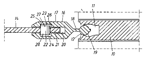
Figure 1 shows schematically a headbox designed to
deliver a three-layer jet of stock into a gap 1 leading
to a forming zone in a twin wire former of roll type. The
twin wire former has an inner forming wire 2, a rotatable
forming roll 3, an outer forming wire 4 and a rotatable
breast roll 5.
The headbox has a turbulence generator including a group
of turbulence channels 6 and a slice 7 arranged
downstream of the turbulence channels 6 and containing a
chamber 8 that converges from its upstream end in the
direction of the flow of stock and terminates in a slice
opening 9 at its downstream end.
The turbulence channels 6 are arranged in three sections
for supplying three different stocks, for instance, into
the slice chamber 8. The lower section and the middle
section each have two rows of turbulence channels 6
arranged close together, while the upper section has
three such rows of turbulence channels 6. The rows of
turbulence channels 6 extend in the cross machine
direction and adjacent rows of turbulence channels 6 are
separated by elongate stable anchoring elements 10
extending in the cross machine direction. The anchoring
element 10 has an elongate, through engagement groove 11
(see Figure 2), with a side opening 12 facing the slice
chamber 8. The group of turbulence channels 6 is
connected at its upstream end to a feeding system (not
shown) comprising three stores of stock and suitable flow
spreaders for uniform distribution of each stock to the
CA 02407913 2002-11-07
WO 01/98583 PCT/SE01/01368
8
rows of turbulence channels 6 in the associated section
and uniform distribution of the stock within each row of
turbulence channels 6.
In the embodiment shown the headbox has six vanes 14
which divide the slice chamber 8 into seven converging
channels 15 communicating with the rows of~turbulence
channels 6. Two of the vanes 14 constitute
stock-separating vanes 14a that are arranged to separate
the three stocks from each other and extend through the
slice opening 9 a predetermined distance to form a jet
which thus consists of three layers. The stock-separating
vanes 14a also have turbulence-generating function. The
other vanes are only turbulence vanes 14b having their
free ends situated inside the slice chamber at a
predetermined distance from the slice opening 9. The
vanes 14 are relatively rigid and may consist of a metal
material, usually titanium, or a plastic material,
usually glassfiber-reinforced or carbonfiber-reinforced
epoxy resin. The vanes 14 are sufficiently stiff to
support various pressures and.velocities of the flows of
stock. Each vane 14 is arranged to be detachably mounted
to said anchoring element 10 by means of an mounting
arrangement comprising an elongate structural element 16
and engagement members 22 arranged in the upstream end
portion 21 of the vane 14. In the embodiment shown the
structural element l6 consists of a connection bar and
the engagement members 22 of cylindrical engagement
dowels (see Figure 2) disposed at right angles to the
plane of the vane 14. The connection bar 16, consisting
of metal, e.g. bronze, is the same length as the width of
the vane 14 and includes in the following order an
engagement part l7 situated downstream, a flexible waist
part l8, and an engagement part 19 situated upstream and
forming a pivot. The engagement part 17 is provided with
an elongate, through groove 20 to receive the upstream
end portion 21 of the vane 14 and its engagement dowels
CA 02407913 2002-11-07
WO 01/98583 PCT/SE01/01368
9
22 to secure the vane 14 and connection bar 16 to each
other, seen in the machine direction. The groove 20 is
provided with inner, opposing recesses 23, 24 with
support walls 25 and 26, situated downstream and
upstream, respectively, that are at right angles to the
plane of the vane 14. The engagement part 19, which has
substantially circular cross section, is received in the
engagement groove 11 of the anchoring element 10 to
pivotally secure the connection bar 16 in machine
direction.
Each engagement dowel 22 has opposing free end portions
27, 28 protruding from the flat sides of the vane 14. The
length of the engagement dowel 22 is somewhat less than
the distance between the bottom surfaces of said inner
recesses 23, 24. The diameter of the engagement dowel 22
is somewhat less than the width of the recesses 23, 24.
To illustrate the principle of how the compressive
stresses mentioned in the introduction, and the buckling
associated therewith can arise, reference is made to
Figures 3-6 showing schematically one of the vanes 14
described above with respect to the attachment
arrangement according to conventional technique. The vane
14 has an upstream edge 29, a downstream edge 30 parallel
therewith, and two parallel side edges 31, 32 parallel
with each other which extend.between the upstream and
downstream edges. The support walls 25, 26 shown in
Figure 2 are illustrated in Figures 3-4 by two parallel,
broken lines. The engagement dowels 22 are placed with
mutually identical distance from each other in a row as
straight as possible within a predetermined first
tolerance interval in relation to a line running parallel
to and at a predetermined distance from the upstream edge
29 of the vane 14. The support wall 25 situated
downstream is made as straight as possible from end to
end within a predetermined second tolerance interval. As
CA 02407913 2002-11-07
WO 01/98583 PCT/SE01/01368
a result of one or both of said tolerance intervals the
positions of the engagement dowels 22 in relation to the
downstream support wall 25 may vary. This is illustrated
in Figure 3 in that the engagement dowel 22e is situated
5 downstream, i.e. closer to the downstream support wall 25
than the other engagement dowels 22. Figure 4 shows the
vane 14, made of metal, during operation where shearing
forces caused by the stocks flowing along the vane 14
press the engagement dowels 22 towards the downstream
10 support wall 25. The shearing forces act along the
.surfaces of the vane 14 and are illustrated in Figure 4
by downwardly directed force arrows designated Fs. The
retaining forces exerted by the downstream support wall
25 on the engagement dowels 22 are illustrated by
upwardly directed force arrows designated Fr. Since, as
can be seen in Figure 4, the initial position of the
engagement dowel 22e is downstream of the other
engagement dowels 22, the retaining force Fr, acting on
the engagement dowel 22e, is greater than the retaining
forces Fr acting on the adjacent engagement dowels 22. As
a result of the loading that then arises, the vane 14 is
subjected to a bending moment in machine direction, which
is illustrated in Figure 4 by moment arrows denoted Mb at
both side edges 31, 32 of the vane 14. The bending moment
causes compressive stresses in the downstream end portion
33 of the vane 14, in the cross machine direction,
illustrated in Figure 4 by tension arrows designated St.
The compressive stresses St buckle the vane 14, as
illustrated in Figure 4 by the wave-shaped lines in the
downstream end portion 33.
As mentioned earlier, buckling may arise in a vane made
of a moisture-absorbing plastic material and having
narrowing thickness in the machine direction, as a result
of the thinner, downstream end portion of the vane
becoming saturated earlier than the thicker upstream end
portion of the vane. Such a vane 14 is described in the
CA 02407913 2002-11-07
WO 01/98583 PCT/SE01/01368
11
following with reference to Figures 5 and 6 where the
vane 14 is shown in unloaded state after, for instance, a
certain operating period when it has been in contact with
the flowing stocks. As the downstream end portion 33 of
the vane 14 becomes saturated in the direction away from
the downstream edge 30, the downstream end portion 33
becomes stretched in the cross machine direction, while
the thicker, unsaturated upstream end portion 21 of the
vane 14 retains its dimensions. For that reason tensions
arise in the vane 14 causing the vane to bend in its
plane so that the downstream edge 30 of the vane
endeavour to assume a convex form and its upstream edge
29 a concave form, as shown in Figure 5. During operation
the load distribution between the engagement dowels 22
becomes non-uniform since the intermediate engagement
dowels 22 take up a larger part of the retaining force
than the engagement dowels 22 situated closer to the side
edges 31, 32 of the vane 14, in the same way as for the
vane shown in Figure 4. In this case the resultant
loading also leads to a bending moment in machine
direction, compressive stresses in the cross machine
direction in the downstream end part 33 of the vane 14
and buckling of the downstream end portion 33 of the vane
14. As will be understood, the tolerance-dependent
buckling described in connection with Figures 3 and 4
also can arise in such a vane made of plastic material
and therefore reinforce the buckling described above,
caused by swelling.
Figure 7 shows an unloaded vane 14 with parts of a
mounting arrangement in accordance with a first
embodiment of the invention. Figure 8 shows the same vane
14 during operation. The vane 14 is symmetrical with
respect to its centre line 34, which coincides with the
machine direction. An outer engagement dowel 22a is
arranged in the proximity of each side edge 31, 32 of the
vane 14, for cooperation with the downstream support wall
CA 02407913 2002-11-07
WO 01/98583 PCT/SE01/01368
12
25 during operation in order to take up the shearing
forces Fs, caused by the flowing stocks that load the
vane 14. An inner area or central part 35 of the upstream
end portion 21 of the vane 14, that extends between the
two outer engagement dowels 22a, is free from engagement
dowels so that said inner area 35 of the vane 14 is
arranged to be able to move freely in the machine
direction in relation to the support wall 25, as is the
upper part of the vane situated downstream of said inner
area 35. Said displacement may be caused by a change in
the velocity of the stock flow or, if the vane 14
consists of a plastic material and has narrowing
thickness in the machine direction, by altered tension
conditions in the vane 14 as a result of swelling going
on. The retaining forces Fr and the shearing forces Fs
together create a bending moment Mb that bends the vane
14 in its plane, stretches the downstream edge 30 of the
vane 14 and generates tensile stresses in the cross
machine direction in the downstream end portion 33 of the
vane 14. These tensile stresses are illustrated in Figure
8 by stress arrows denoted Sd. The displacement may arise
during a first period of time which, for a metal vane, is
calculated from the moment when the headbox starts to the
moment when a specific machine speed has been reached. If
the machine speed shall subsequently be increased a
second period of time commences, extending between the
first and second machine speeds. When the vane consists
of a plastic material, a first period of time will extend
from the moment when the flows of stock start flowing
through the headbox up to the moment when the swelling of
the vane is complete, whereupon the same or altered
machine speeds can be used during this period of time.
After swelling is complete a second period of time can be
started extending up to the moment when a desired higher
machine speed has been reached. Since there are no
engagement dowels in the central area 35, the central
'area 35 of the vane can move freely forwards without
CA 02407913 2002-11-07
WO 01/98583 PCT/SE01/01368
13
other restrictions than the strength of the vane at the
attachment locations for the outer engagement dowels 22a
and the position of the downstream edge 30 which must not
be such that the stock layering is affected unfavourably.
In such an embodiment no compressive stresses can arise
in the downstream end portion 33 of the vane.
Figure 9 shows an unloaded vane 14 with parts of a
mounting arrangement in accordance with a second
embodiment of the invention where three engagement dowels
22b, forming an outer group 36, are arranged in the
proximity of each side edge 31, 32 of the vane 14. The
engagement dowels 22b are arranged adjacent each other in
a row in the cross machine direction. Here too, the inner
area 35 of the upstream end portion 21 of the vane,
extending between the two outer groups 36 is free from
engagement dowels so that said inner area~35 of the vane
14, as well as the area downstream of this, are arranged
to be able to move freely in the machine direction in
relation to the downstream support wall 25. The retaining
forces Fr and the shearing forces Fs together create a
bending moment Mb as shown in Figure 10. The bending
moment Mb bends the vane 14 in its plane, stretches the
downstream edge 30 of the vane 14 and generates tensile
stresses Sd in the cross machine direction in the
downstream end portion 33 of the vane 14. The
displacement arises under the same circumstances as those
described for the vane in accordance with Figure 7.
Figure 11 shows an unloaded vane 14 with parts of a
mounting arrangement in accordance with a third
embodiment of the invention, which is more suitable for
high stock-flow velocities, than the embodiments described
previously. The vane 14 is provided with engagement
dowels 22b, arranged in outer groups 36, as in the second
embodiment described in connection with Figures 9 and 10,
as well as engagement dowels 22c arranged in two inner
CA 02407913 2002-11-07
WO 01/98583 PCT/SE01/01368
14
groups 37 with three engagement dowels 22c in each group
37. The inner groups 37 of engagement dowels 22c are
arranged at a predetermined distance from the outer
groups 36. Each inner group 37 of engagement dowels 22c
is arranged at a predetermined distance from the
downstream support wall 25, e.g. about 5 mm. The distance
to the outer group 36 of engagement dowels 22b can then
be about 2000 mm. A first period of time commences with
the stocks starting to flow through the headbox and
finishes, e.g. when the inner groups 37 of engagement
dowels 22c come into contact with the downstream support
wall 25 in that the inner area 35 has been displaced in
the machine direction under the influence of the shearing
forces Fs from the stocks, whereupon the downstream edge
30 of the vane 14 is stretched and a tensile stress Sd in
the cross machine direction is built up in the downstream
end portion 33 of the vane 14. At the end of the period
of time the machine speed has a predetermined value. It
will thus be understood that the position of each inner
group 37 of engagement dowels 22c in relation to the
downstream support wall 25 and to the outer group 36 of
engagement dowels 22b is decisive for each stock flow
rate. During a second period of time, extending up to a
moment when an increased machine speed has been set, the
inner part-area 35a, defined by the inner groups 37 of
engagement dowels 22c, moves forwards in machine
direction, the movement being limited by the displaced
position when there is a risk of compressive stresses
appearing in the downstream end portion 33 of the vane
14. When the vane consists of a plastic material and is
narrowing, the swelling phenomenon must also be taken
into account in choosing maximum stock flow rate or
machine speed and determining the positions of the inner
groups 37 of engagement dowels 22c. Instead of increasing
the machine speed from the existing value when the inner
groups 37 of engagement dowels 22c are in contact with
the downstream support wall 25, the tensile stress that
CA 02407913 2002-11-07
WO 01/98583 PCT/SE01/01368
still exists in the downstream end portion 33 of the vane
can be utilized to compensate the compressive stresses
deriving from the swelling.
5 In a vane 14 consisting of plastic material and having a
length of 800 mm, a width of 5500 mm, a thickness of the
upstream end portion 21 of 4 mm, a thickness of the
downstream end portion 33 of 0.5 mm, and which is
intended to be subjected to a maximum stock flow rate of
10 2000 m/min, for instance, a suitable distance between two
adjacent outer and inner groups 36, 37 may be about
2000 mm. In this case the inner groups 37 of engagement
dowels 22c may be situated about 5 mm from the downstream
support wall 25, seen in unloaded state of the vane 14.
15 The engagement dowels in each group 36, 37 are preferably
placed about 50 mm from each other. It is preferable to
arrange the engagement dowels 22b and 22c within each
group 36, 37 so that the distance to the downstream
support wall 25 increases in two adjacent engagement
dowels in the direction from the closest side edge
31, 32, respectively, of the vane 14. A suitable increase
in this distance is about 0.1 mm.
It will be understood that the invention is not limited
to three engagement dowels 22 in each group. More or
fewer, e.g. two or four engagement dowels 22, may be used
in each group. Ne°i.ther is the invention limited to two
inner groups 37 of engagement dowels 22. It is thus
possible, for instance, to place additional inner groups
of engagement dowels 22, spaced from the support wall 25,
between the outer and inner groups 36, 37.
Figure 13 shows an unloaded vane 14 with parts of a
mounting arrangement in accordance with a fourth
embodiment of the invention, the engagement dowels 22
being arranged in a row along a curved line extending
between the side edges 31, 32 and symmetrical about the
CA 02407913 2002-11-07
WO 01/98583 PCT/SE01/01368
16
centre line 34. In the embodiment shown the engagement
dowels 22 are arranged with uniform spacing but in
accordance with an alternative embodiment (not shown) the
spaces may be different and distributed in a regular
pattern, e.g. groups of engagement dowels with equal
distance between them within the group and equal but
greater distance between the groups. In the embodiment
shown in Figure 13 a certain number, e.g. 3-5, of the
engagement dowels situated nearest a side edge 31, 32 may
be considered to be included in an outer group of
engagement dowels, whereas the other engagement dowels
may be considered to constitute separate inner engagement
dowels situated one after the other, or to form inner
groups of engagement dowels, depending on the shape of
the curved line and the distance between the engagement
dowels as mentioned above. If the highest machine speed
is to be used immediately for such a vane, a period of
time commences at the moment when the stocks start
flowing through the headbox and extends to the moment
when the engagement dowels 22 closest to the centre line
34 also come into contact with the downstream support
wall 25 as a result of the influence of the shearing
forces Fs from the stocks, whereupon the downstream edge
is stretched and a tensile force Sd in the cross
25 machine direction is built up in the downstream end
portion during this period of time, as illustrated in
Figure 14. If the vane consists of a plastic material, is
narrowing and can no longer be moved forwards within the
central area, there may be such a large excess of tensile
30 stress in the downstream end portion at the end of said
period of time that remaining swelling gives compressive
stresses that are balanced by said excess of tensile
stress. If the tensile stress decreases to zero and the
vane is still not saturated, i.e. the swelling is going
on, said maximum machine speed must be reduced in a
corresponding degree. It will be understood that periods
of time shorter than that described exist which thus
CA 02407913 2002-11-07
WO 01/98583 PCT/SE01/01368
17
terminate at a moment when a lower machine speed than the
maximum is set and corresponds to a specific displacement
of the inner area so that at least two inner engagement
dowels or two inner groups of engagement dowels situated
at a distance from the centre line 34 of the vane, are in
contact with the downstream support wall 25.
In the vane shown in Figure 13 the engagement dowels are
arranged in a row along a curved line which, when the
vane is unloaded, has a certain extension in the machine
direction. By mounting such a vane in a connection bar
where the distance between the previously mentioned
support walls is less than the extension of the curved
line in the machine direction, tensile stresses in the
downstream end portion of the vane can be provided
already when the vane is mounted in the groove of the
connection bar. Through the narrow groove recess, in
relation to the curved line, forming said support walls,
the outer engagement dowels situated closest to the side
edges of the vane will be caused, upon insertion of the
vane into the groove, to cooperate with the support wall
situated downstream of the groove and will absorb support
forces therefrom. In corresponding manner, the inner
engagement dowels situated nearest the centre line of the
vane will cooperate with the support wall situated
upstream of the groove and will absorb support forces
therefrom. In the same way as the above-mentioned
shearing and retaining forces, the support forces will
bend the vane in its plane, stretch the downstream edge
of the vane and generate tensile stresses in the cross
machine direction in the downstream end portion of the
vane. These tensile stresses ensure that the vane is flat
right at the start-up phase of the headbox, i.e. before
the stocks have had time to influence the vane.
To make sure that the downstream edge of the vane is
straight or substantially straight at a certain machine
CA 02407913 2002-11-07
WO 01/98583 PCT/SE01/01368
18
.speed, e.g. maximum speed (without compressive stresses
arising), this downstream edge may be pre-shaped to an
extent equivalent to the displacement the vane is able to
perform until the flows of stock act with a constant
shearing force at said machine speed and/or the vane is
completely saturated, when this consists of a plastic
material and has narrowing thickness. Figures 13 and 14
illustrate a vane having such a pre-shaped concave
downstream edge 30 with the same curvature as the curved
line along which the engagement dowels 22 are arranged.
The concave downstream edge 30 is then stretched to
straight form upon said loading of the vane. The side
edges 31, 32 have also been pre-shaped to incline in
relation to the centre line 34.
In accordance with an alternative embodiment (not shown)
the inner engagement dowels are arranged along a straight
line in which the outer engagement dowels or the outer
groups of engagement dowels are situated, in which case
the downstream support wall is designed with small
recesses or with sections of larger recesses or with a
predetermined concave shape, e.g. circular arc-shaped,
thereby enabling free displacement of the vane even in
this mirror-image relationship. It is also possible to
give the downstream end wall a concave shape with a '
predetermined first radius, and arrange the engagement
dowels along a curved line with a predetermined second
radius that is larger than said first radius.
According to the invention buckling of the vane 14 is
avoided by arranging one or more engagement dowels 22 in
the proximity of the side edges 31, 32 of the vane 14 in
order, as substantially the only engagement dowels 22 and
at least during a limited period of time, to cooperate
with the support wall 25 situated downstream in order to
take up said shearing forces, while at the same time the
inner area 35 of the upstream end portion 21 of the vane
CA 02407913 2002-11-07
WO 01/98583 PCT/SE01/01368
19
14 can move freely, i.e. without influence from outer
retaining forces from engagement dowels, in the machine
direction in relation to the downstream support wall 25
during said period of time or part thereof. By arranging
the engagement dowels 22 in the manner described above
they create, during operation, shearing forces Fs acting
on the vane 14, together with the retaining forces Fr
acting on the engagement dowels 22 a bending moment Mb,
which under normal operating conditions always bends the
vane 14 in its plane and generates tensile stresses Sd in
the cross machine direction in the downstream end portion
33 of the vane 14. The placing of the engagement dowels
22 in accordance with the principle of the invention
prevents that the compressive stresses described
previously will arise in the downstream end portion 33 of
the vane 14. A characteristic feature of the invention is
thus that compressive stresses are prevented in the vane,
which compressive stresses may cause the vane to buckle
so that the stock layering may be affected in an
unfavourable manner.
The invention has been described above in connection with
engagement members in the form of engagement dowels 22.
However, it will be understood that the invention can be
realized with other types of engagement 'members. Besides
the engagement members being designed as a plurality of
discrete elements such as engagement dowels, they may
consist of a continuous engagement element cooperating
with said downstream support wall in accordance with the
principles of the invention.
It will also be understood that the invention can be
realized using other mounting arrangements than those
described above. The vane 14 may be attached directly to
the anchoring element 10, for instance, which then has
the same function as the elongate connection bar 16 and
CA 02407913 2002-11-07
WO 01/98583 PCT/SE01/01368
has a groove with support walls similar to that in the
connection bar.