Note: Descriptions are shown in the official language in which they were submitted.
CA 02407916 2002-11-07
WO 01/98629 PCT/US01/18092
METHOD AND APPARATUS FOR COMMUNICATING WITH
DOWNHOLE DEVICES IN A WELLBORE
BACKGROUND
The invention relates to methods and apparatus for communicating with
downhole devices in a wellbore.
Oil and gas wells may be completed with a variety of downhole devices to
produce hydrocarbons from, or inject fluids into, formations beneath the
earth's
surface. Completion equipment have been developed for many types of wells,
including vertical or near-vertical, horizontal, highly deviated, and
multilateral wells.
Typical completion equipment include valves, tubing, packers, and other
downhole
devices for fluid flow control, as well as electrical devices such as sensors
and control
devices to monitor downhole conditions and/or to control actuation of
completion
devices (e.g., opening or shutting valves, setting packers, and so forth).
More recently, to provide for data acquisition and control of wells,
intelligent
completion systems (ICS) have been proposed or developed to enable a well
surface
operator to monitor and control the production of hydrocarbons from multiple
zones
in a single wellbore or from individual lateral wellbores in a multilateral
well. An ICS
is used to reduce the number of interventions needed during the life of the
well since
downhole conditions can be monitored and production can be controlled
remotely.
Typically, an ICS includes surface (or remote) control equipment and downhole
modules that are in communication with the surface (or remote) control
equipment.
The ICS downhole modules may include sensors for measuring tubing and annulus
pressure, temperature, and flow rates as well as control devices to actuate
valves and
other downhole devices.
In some ICS completion systems, a single electrical cable is run from the
surface to connect to the downhole modules (sometimes referred to as an I-wire
connection). Thus, control signals, as well as power, can be sent from the
surface
down the electrical cable to the downhole modules, and measurement data
obtained by
the downhole modules can be communicated up to surface through the same cable.
However, there may be locations in a well that are difficult to access by an I-
wire
1
CA 02407916 2007-07-18
78543-105
connection. One example is aSand face completion, in which
screens or gravel packs are typically run in segments. As a
result, wet connections may have to be made between the
segments, which may be impract_Lcal and unreliable. Thus, a
need arises for more practical and reliable techniques of
deploying electrical devices in remote locations in a well,
such as a sand face completion in a well.
S UMDIARY
In general, according to one embodiment, an
apparatus for use in a wellbore comprises an adapter capable
of being attached to a carrier line to enable the apparatus
to be run into the wellbore. The apparatus further includes
an inductive coupler portion, a device for performing a task
in the wellbore, and an electrical link between the
inductive coupler portion and the device.
In general, according to another embodiment, a
system for use in a wellbore comprises a communications
module, a remote module in the wellbore, and equipment
having a plurality of sections installed separately in the
bore. The remote module is positioned past at least one of
the sections. An inductive coupler link is between the
remote module and the communications module.
In general, accordinq to yet another embodiment,
there is provided apparatus for use in a wellbore,
comprising: an adapter capable of being attached to a
carrier line to enable the apparatus to be run into the
wellbore; a first inductive coupler portion; sand control
equipment, a device for perforrning a task in the wellbore
and to be positioned proximate the sand control equipment;
and an electrical link between the first inductive coupler
portion and the device, wherein the first inductive coupler
2
CA 02407916 2007-07-18
78543-105
portion is adapted to be positioned in the proximity of
second, downhole inductive coupler portion to enable the
first inductive coupler portion to communicate with the
second inductive coupler portion.
In general, according to still another embodiment,
there is provided a system for use in a wellbore,
comprising: a first inductive coupler portion; an electrical
cable connected to the first inductive coupler portion; a
tool capable of being run into the wellbore, the tool
comprising: a second inductive coupler portion adapted to be
positioned in the proximity of the first inductive coupler
portion to communicate with the first inductive coupler
portion; a device for performing a task in the wellbore; and
an electrical link between the second inductive coupler
portion and the device; and sand control equipment, wherein
the device of the tool is to be positioned proximate the
sand control equipment.
In general, according to a further embodiment,
there is provided a system for use in a bore of a well,
comprising: a communications module; a remote module in the
wellbore; sand control equipment having a plurality of
sections installed separately in the bore, the remote module
positioned past at least one of the sections; and an
inductive coupler link between the remote module and the
communications module.
In general, according to a yet further embodiment,
there is provided a method of performing a task in a
wellbore, comprising: lowering a tool comprising a first
inductive coupler portion and a device into the wellbore;
positioning the first inductive coupler portion at a first
depth and the device at the second depth, wherein the first
inductive coupler portion is positioned in the proximity of
2a
CA 02407916 2007-07-18
78543-105
a second inductive coupler portion located near the first
depth, wherein the device is positioned proximate sand
control equipment; and activating the device to perform the
task.
Other features and embodiments will become
apparent from the following description, from the drawings,
and from the claims.
BRIEF DESCRIPTION OF THE DRAWING
Fig. 1 illustrates an embodiment of completion
equipment including various downhole modules positioned in a
wellbore.
Fig. 2 illustrates a downhole module in accordance
with an alternative embodiment that includes a first
inductive coupler portion for communicating power and
signals.
Fig. 3 illustrates a carrier device for carrying a
second inductive coupler portion in accordance with the
alternative embodiment for mating with the first inductive
coupler portion of Fig. 2.
Fig. 4 illustrates a side pocket mandrel adapted
to receive a downhole module in accordance with one
embodiment.
2b
CA 02407916 2002-11-07
WO 01/98629 PCT/US01/18092
Fig. 5 is a block diagram of an inductive coupler communications mechanism
including the first and second inductive coupler portions of Figs. 2 and 3 and
components in the downhole module of Fig. 4.
DETAILED DESCRIPTION
In the following description, numerous details are set forth to provide an
understanding of the present invention. However, it will be understood by
those
skilled in the art that the present invention may be practiced without these
details and
that numerous variations or modifications from the described embodiments may
be
,possible.
As used here, the terms "up" and "down"; "upper" and "lower"; "upwardly"
and "downwardly"; and other like terms indicating relative positions above or
below a
given point or element are used in this description to more clearly describe
some
embodiments of the invention. However, when applied to equipment and methods
for
use in wells that are deviated or horizontal, such terms may indicate a left-
to-right,
right-to-left, or diagonal relationship as appropriate. Further, "proximal"
refers to a
shallower point of a wellbore while "distal" refers to a deeper point of the
wellbore.
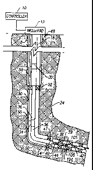
. Referring to Fig. 1, an embodiment of completion equipment positioned in a
wellbore 8 is illustrated. The wellbore 8 may have a deviated section 38. An
upper
section of the wellbore 8 is lined with casing 48, and a main production
tubing 18
extends from wellhead equipment 12 at the surface into the wellbore 8. The
main
production tubing 18 connects to a pipe 46 that extends into a lower wellbore
section.
In one embodiment, the completion equipment in the wellbore 8 may include
an intelligent completion system (ICS) having downhole modules with sensors
and
control devices. Alternately, the completion equipment may include other types
of
systems, such as permanent monitoring systems (PMS) and other systems having
downhole modules for monitoring well conditions or controlling well equipment.
As
illustrated, two downhole modules 20 and 34 in the ICS are attached to the
main
tubing 18 and the lower pipe 36, respectively. In further embodiments, a
greater or
lesser number of modules may be connected in the system. Such downhole modules
may include various types of electronics, including control units (e.g.,
3
CA 02407916 2002-11-07
WO 01/98629 PCT/US01/18092
microprocessors, microcontrollers, and so forth), storage devices,
electrically-
activable actuation devices (which may be linked to valves), and/or sensor and
monitoring devices.
The modules 20 and 34 may be electrically coupled to an electrical cable 50
(that may include one or more electrical conductors) extending from the
surface. The
electrical cable 50 communicates power and signals between or among the
downhole
modules 20 and 34 and a surface controller 10 coupled to the wellhead
equipment 12.
The surface controller 10 may be physically located at the well surface or at
some
distant location in communication (wired or wireless) with the wellhead
equipment
12. The cable 50 may be routed through various downhole components, including
packer 52, to the modules 20 and 34.
A module 44 including control and/or sensor devices may be positioned in the
deviated wellbore section 38. In one example arrangement, the deviated
wellbore
section 38 may include gravel pack and screen assemblies 40 and 42 attached to
a
tubing 39 positioned inside the deviated wellbore section 38 as part of a sand
face
completion. Each gravel pack and screen assembly includes a gravel pack
positioned
between the outside of the screen and the inner wall of the deviated wellbore
section
38. Fluids from the surrounding formation flow into the deviated wellbore
section 38
and through the screen and gravel pack assemblies 40 and 42 into the lower
pipe 36.
As is typical, the sand face completion equipment including the gravel pack
and
screen assemblies 40 and 42 are assembled in sections in the deviated wellbore
section 38 (or in any other location in the wellbore 8). A communications
module,
such as module 44, attached between the sections of the sand face completion
equipment would have to make wet connections during assembly if an electrical
wired
connection is desired. However, in accordance with one embodiment, an
inductive
coupler system 47 is used through which the module 44 in the lower deviated
wellbore section 38 may communicate with a main communications module (e.g.,
module 20 or 34 or the surface controller 10).
As used here, a "remote module," such as module 44, may be any.
communications module (control module or monitoring module) that is capable of
communicating with another device (downhole or at the well surface) and that
is
4
CA 02407916 2002-11-07
WO 01/98629 PCT/US01/18092
attached below or past a separately installed downhole component, such as sand
control equipment. The remote module is capable of performing a task, such as
a
monitoring task, a measurement task, or a control task. Due to the positioning
of the
remote module, a wet connection would be required if direct electrical contact
is
desired. This is typically the case where a completion string is installed in
separate
segments. One example involves modules placed in sand control assemblies that
are
installed in separate segments. Another example involves any other completion
string
where separate sections may be desirable. For example, where it is known that
one
part of a completion string will be pulled out of a wellbore more frequently
than
another part, such as for work-over operations, it may be desirable to install
the
completion string in separate segments. A submersible pump is an example of a
part
that may require more frequent repairs than other components.
Thus, as used here, a remote communications module is "separate" from
another downhole equipment section if the remote communications module and
downhole equipment are installed into the wellbore 8 separately. A remote
module is
said to be "past" the separate downhole equipment section if it is more distal
from the
wellbore surface than the separate downhole equipment section.
In the illustrated embodiment of Fig. 1, the module 44 may be powered by
electrical power inductively coupled from a main module. Alternatively, the
module
44 may be powered by a power supply 104 that includes a battery, for example.
To
extend the life of the battery in the power supply 104, a long-life battery
may be used
or a remote module 44 that has relatively low power consumption may be used.
For
example, one technique to reduce power consumption may be to keep the module
44
in a standby or off state when inactive. Another technique of reducing power
consumption is to activate the remote module 44 only during set times, such as
once a
day or some other set period. Thus, for example, if the remote module 44 is a
monitoring device, then the module 44 may be powered on at a predetermined
time to
take a measurement. The module 44 then communicates the measured data to the
main module 20 or 34 or the surface controller 10. After the measurement data
has
been communicated, the remote module 44 may be powered back down to either the
standby or off state. If the remote module 44 includes control devices, such
control
5
CA 02407916 2002-11-07
WO 01/98629 PCT/US01/18092
devices may be powered up from an off state or a standby state in response to
receipt
of a command.
In a further embodiment, a mini-turbine 106 may also be located in the
proximity of the remote module 44. The mini-turbine 106 is attached to a
trickle
charger 105 that may be used to charge the battery 104. The mini-turbine 106
may be
mounted in a pocket and is activated by fluid flow in the deviated wellbore
section 38.
When activated, the mini-turbine 106 generates power to re-charge the battery
104.
To communicate with the module 44, the inductive coupler system 47 is used.
The inductive coupler system 47 is connected to the main cable 50. Examples of
inductive coupler systems include those described in U.S. Patent No.
4,806,928,
entitled "Apparatus for Electromagnetically Coupling Power and Data Signals
Between Wellbore Apparatus and the Surface," by Anthony F. Veneruso, which is
hereby incorporated by reference.
One embodiment of an inductive coupler system includes a male coil element
and female coil element, in which the female coil element is positioned
downhole and
the male coil element is lowered into close proximity with the female coil
element so
that an electrical current generated in one of the coil elements is
inductively coupled
to the other coil element. Referring to Figs. 2 and 3, the inductive coupler
system 47
according to the one embodiment includes a female coil element 202 attached to
the
lower end of a tubing 200 (Fig. 2), which may be the pipe 36 (Fig. 1), and a
male coil
element 216 attached in a connector housing 214 (Fig. 3). The connector
housing 214
and a sensor or control module 210 (which may be the remote module 44 in Fig.
1) is
part of a remote module assembly 205 that may be carried into the well by a
carrier
line 212 (which may be wireline, slickline, or coiled tubing).
In one embodiment, the tubing 200 extends to a region above an upper sand
face completion section 204, which may be located in a vertical wellbore
section, a
horizontal wellbore section, or a deviated wellbore section. Additional sand
face
completion sections may be present in the wellbore, such as a lower sand face
completion section 240. It may be desirable to position a sensor or control
module
between the sand face completion sections 204 and 240 (which may correspond to
sections 40 and 42 in Fig. 1), generally in a region indicated as 206 in Fig.
2. One
6
CA 02407916 2002-11-07
WO 01/98629 PCT/US01/18092
possibility is to install such a module in the region 206 after the lower sand
face
completion section has been assembled but before the upper sand face
completion
section 204 is installed. However, to make a wired electrical connection to
such a
module in the region 206 (a remote location) would require use of a wet
connection
between a wire routed through the upper sand face completion section 204 and
the
remote module. In accordance with an embodiment of the invention, to avoid
employing wet connections, an inductive coupler connection is employed to
enable
communication between a remote module placed in the region 206 and one of the
main modules further up the welibore or at the well surface over an electrical
cable
203 (which may correspond to cable 50 in Fig. 1).
The remote module assembly 205 carrying the remote module 210 to be
deployed in the region 206 may be lowered through a bore 223 of the female
coil
element housing 201 and a bore 221 of the sand face assembly 204 so that the
remote
module 210 may be engaged in a receiving housing 207. The connector housing
214
in the remote module assembly 205 may have a locking mechanism 222 (e.g.,
locking
dogs) to engage a corresponding profile 224 in the female coil element housing
201.
A locking mechanism 226 may also be formed on the external surface of the
remote
module 210 to engage a mating profile 228 in the receiving housing 207. In the
remote module assembly 205, one or more electrical conductors 215 may extend
through a middle housing section 217 (or outside of the middle housing section
217)
to provide an electrical link between the male coil element 216 and the remote
module
210.
In operation, once the remote module assembly 205 is locked in place, a
releasable adapter 230 coupling the carrier line 212 to the remote module
assembly
205 may be released to remove the carrier line 212 from the wellbore, leaving
behind
the remote module 210 and male coil element 216. The male coil element 216 is
at a
first depth (at a proximal end of the sand control equipment) while the remote
module
210 is at a second depth (past at least one of the sections of the sand
control
equipment). Power is provided down the electrical cable 203 to the female coil
element 202. Once the male coil element 216 is in engaging proximity with the
female coil element 202, the power may be inductively, coupled from the female
coil
7
CA 02407916 2002-11-07
WO 01/98629 PCT/US01/18092
element 202 to the male coil element 216, which transfers the power down the
electrical conductor(s) 215 to the remote module 210. If the remote module 210
is a
sensor module, then measurement data gathered by the remote module may be
communicated as electrical signals over the conductor(s) 215 to the male coil
element
216. The male coil element 216 in turn couples the communicated signals to the
female coil element 202 for transmission up the electrical cable 203.
By using an inductive coupler mechanism to provide a communications path to
a remote module, a wet wired connection can be avoided. An added advantage of
using an inductive coupler mechanism in accordance with one embodiment is that
a
separate power supply may not be needed in the remote module, which reduces
cost of
deploying modules at remote locations as well as reduces the size of such
remote
modules.
Referring to Fig. 4, another technique of positioning a remote module 210 in a
remote location, such as region similar to region 206 in Fig. 2, is by use of
a side
pocket mandre1330 attached between upper and lower sand face completion
sections
302 and 304. The side pocket mandre1330 includes a main passageway 334 as well
as a side passageway 332. The side passageway 332 may be adapted to receive a
remote module 310 (corresponding to remote module 44 in Fig. 1). The side
pocket
mandre1330 includes an orienter mechanism 338 to direct the remote module 310
into
the side passageway 332. A wire 340 connected to the remote module extends
upwardly past the upper sand face completion section 302 to an inductive
coupler
mechanism similar to that disclosed in Figs. 2 and 3.
The inductive coupler mechanism according to further embodiments may also
be used to deploy remote sensor or control modules in other remote locations
in the
wellbore 8. Such locations may include any other location in which completion
equipment is assembled in different stages or segments which would require use
of
wet connections if wired connections are desired.
Referring to Fig. 5, a portion of the inductive coupler communications
mechanism is illustrated. The female coil element 202 is coupled by the
electrical
cable 203 to at least one of the main modules and surface controller 10. The
male coil
element 216 is coupled by an electrical wire 215 to a transceiver 402 in the
remote
8
CA 02407916 2002-11-07
WO 01/98629 PCT/US01/18092
module 210. The transceiver 402 is coupled to a control unit 404, which may be
a
microprocessor, microcontroller, or other control device. The control unit 404
is also
coupled to a storage unit 406 for storing data and instructions. The control
unit 404
can receive data from a sensor transducer 408, which receives measured signals
from
a sensor 410. The control unit 404 may also provide activating commands to an
actuator transducer 412 that translates the commands into signals for
activating an
actuator 414 (e.g., a valve actuator or other actuator). Power communicated
down the
electrical cable 203 is inductively coupled between the female coil and male
coil
elements 202 and 216, with the power transferred over the electrical wire 215
to the
remote module 210.
While the-invention has been disclosed with respect to a limited number of
embodiments, those skilled in the art, having the benefit of this disclosure,
will
appreciate numerous modifications and variations therefrom. It is intended
that the
appended claims cover all such modifications and variations as fall within the
true
spirit and scope of the invention.
9