Note: Descriptions are shown in the official language in which they were submitted.
CA 02408077 2002-10-31
WO 01/77585 PCT/USO1/11085
INTEGRATED REACTOR
Field of the Invention
This invention relates to fuel-gas generation systems for
fuel cells and hydrogen generation equipment.
Background of the Invention
Fuel cells are increasingly becoming an alternative way of
producing electricity for use in commercial and industrial
establishments, electric vehicles, and homes. However, their
rapid assimilation into society is being hindered by the high
costs and hazards associated with using pure hydrogen as a source
of fuel in the fuel cell, and the complexity of small-scale fuel
processors that are incorporated into the fuel cell system.
Various methods of producing a hydrogen-rich air stream for use
as fuel in a fuel cell, by using easily available hydrocarbon
fuels such as natural gas or gasoline as a raw-product, are
currently under development. The successful development of such
systems to avoid current problems will greatly facilitate the
wider acceptance of fuel cells as a commercially viable source
of energy.
Many existing fuel cell systems are, furthermore, currently
not economically feasible due to the large number of components
that go into their fabrication, which greatly add to the cost and
complexity of maintaining such systems. These systems may also
be very complicated to operate and maintain on an on-going basis .
Because of their current arrangement, these systems are also
relatively inefficient with respect to the quantity of fuel cell
fuel-gas actually produced.
There is therefore a need for a fuel cell fuel-gas
generation system which has fewer parts, is easier to fabricate
and maintain, and which operates at a higher efficiency than
currently available fuel cell fuel-gas generation systems.
1
CA 02408077 2002-10-31
WO 01/77585 PCT/USO1/11085
Summary of the Invention
In this specification, a "waste gas oxidizer" (WGO) means
a device wherein unused hydrogen rich fuel-gas or unrecovered
hydrogen is oxidized before being vented to the atmosphere or to
other post-treatment devices. The unused hydrogen rich fuel-gas
may be from the anode of a fuel cell, and the unrecovered
hydrogen may be from, for example, a Thermal Swing Absorber (TSA)
or Pressure Swing Absorber (PSA). The unused or unrecovered
hydrogen is sometimes referred to as tail gas or waste gas. In
a preferred embodiment, the WGO is an anode-off gas oxidizer
(AGO) .
The waste gas may consist mostly of hydrogen, carbon
monoxide, carbon dioxide, light hydrocarbons (such as methane),
and water vapor. Oxygen is preferably added to enable the
hydrogen, carbon monoxide, and hydrocarbons to be oxidized to
water and carbon dioxide. The required oxygen may be provided
either in the form of air or unreacted cathode off gas, or a
mixture thereof, from a fuel cell which contains enough oxygen
for the oxidation reaction.
Typically, a WGO may comprise an enclosed volume with a
first inlet for the hydrogen-rich anode off gas or tail gas, a
second inlet for the~oxygen containing cathode off gas, a means
for igniting the combustible mixture of hydrogen rich anode off
gas and the oxygen containing cathode off gas within the enclosed
space, and an outlet for the products of combustion from the
enclosed space. The reaction of the hydrogen, carbon monoxide,
and hydrocarbons in the anode off gas with the oxygen in the
cathode off gas takes place in the enclosed volume of the WGO and
the unreacted products leave the enclosed volume through the
product outlet.
The enclosed volume can be within a pressure Vessel or a
pipe or a tube, which may be constructed of steel, stainless
steel, steel alloy or another suitable metal. It could also be
2
CA 02408077 2002-10-31
WO 01/77585 PCT/USO1/11085
non-metallic such as glass, composite insulation, ceramics etc.
The two inlets and the outlet can be either formed integrally
with the vessel or they can be separate components which are
attached by welding, soldering, brazing etc. The enclosed volume
is preferably large enough to provide the required residence for
the oxidation reaction to take place to the required degree of
completion. The ignition means can consist of any suitable means
for initiating and maintaining an oxidation reaction such as a
spark-igniter, a flame rod, a hot electric resistance wire, or
a heated metallic or ceramic matrix.
The WGO can be started up and brought up to operating
temperature using auxiliary hydrocarbon fuels such as methane,
propane etc. After the WGO reaches the operating temperature, the
anode off gas or the tail gas can be introduced into the reaction
chamber for oxidation of the hydrogen, carbon monoxide and the
hydrocarbons to carbon dioxide and water. The auxiliary fuel can
then be turned off and the WGO operating temperature can be
maintained by the oxidation of the hydrogen, carbon monoxide and
hydrocarbons in the anode off gas or tail gas to carbon dioxide
and water.
In this specification, an "autothermal reformer" (ATR) is
a device for the conversion of a mixture of hydrocarbon, steam,
and oxygen to a hydrogen-rich gas. The hydrogen rich gas may or
may not also contain carbon monoxide as a byproduct. An ATR may
or may not utilize catalysts for carrying out the above
conversion. However, the use of catalysts in the ATR reduces the
average operating temperature of the conversion reaction.
In an ATR, the primary reactions which facilitate the
conversion of the hydrocarbon to a hydrogen rich gas are a
partial oxidation reaction and steam methane reforming (SMR)
reaction. If catalysts are used for the conversion, the partial
oxidation reaction is generally referred to as a catalytic
partial oxidation (CPO) reaction. The CPO reaction for the
3
CA 02408077 2002-10-31
WO 01/77585 PCT/USO1/11085
conversion of methane is:
CH4 + 0.5(02) ~ CO + 2(H2) + heat.
The CPO reaction is exothermic and therefore has the advantage
of very fast response to a change in the hydrogen demand from the
fuel cell. If a catalyst is not used, the operating temperature
is higher.
The second reaction that takes place in an ATR is the SMR
reaction which is described by the following chemical reaction:
CH4 + H20 + heat ~ CO + 3H2.
This reaction is highly endothermic and may take place without
a catalyst. However, a catalyst is typically used to enable the
reaction to take place at a lower. The SMR reaction provides a
higher quality of hydrogen in response to fuel cell hydrogen-load
demand and improves the process efficiency. Heat energy for the
endothermic SMR reaction is provided by direct heat transfer -and
heat from the partial oxidation of the hydrocarbon in the CPO
reaction described above. Therefore, in an ATR, the exothermic
CPO reaction is balanced by the endothermic heat of the SMR
reaction.
The combination of the CPO and the SMR reactions in the ATR
provides a gas stream with a higher concentration of hydrogen
than that produced by the CPO reaction alone. However, this
combination also provides a faster response to fuel cell hydrogen
load demands than is possible with a SMR reaction alone.
While the ATR consists predominantly of the CPO and SMR
reactions, some water gas shift (WGS) reactions may also occur
within the ATR as described by the following chemical equation:
CO + H20 ~ C02 + H2 + heat.
The WGS reaction reacts some of the CO generated during the CPO
reaction with some of the steam to produce additional hydrogen.
Separate catalysts can be used for the CPO reaction and the
SMR reactions. Alternatively, a combined catalyst in which both
reactions take place can also be used. According to one aspect
4
CA 02408077 2002-10-31
WO 01/77585 PCT/USO1/11085
of the invention, there is provided an integrated reactor for
producing fuel gas for a fuel cell, the integrated reactor
comprising: an waste gas oxidizer (WGO) assembly having an
associated WGO chamber, an inlet, an outlet and a flow path for
exothermic gases produced in the WGO chamber; and an autothermal
reactor (ATR) assembly located at least partially in the WGO
chamber, the ATR assembly having an inlet means and an outlet
means for process gases flowing therethrough and a catalyst bed
intermediate the inlet and outlet means, at least part of the
inlet means of the ATR assembly being located in the flow path
of the WGO chamber.
In one aspect, the present invention relates to an
integrated reactor configuration for the production of a fuel
cell fuel-gas . More particularly, the invention provides for the
integration of an autothermal reformer (ATR) assembly into an
waste gas oxidizer (WGO) assembly. One of the benefits of
integrating an autothermal reformer assembly into the waste gas
oxidizer assembly is to enhance thermal integration so that the
higher temperature heat generated during the operation of the
waste gas oxidizer assembly can be used to advantage. This higher
temperature heat may be transferred into the steam reforming
section of the ATR assembly, allowing for decreased air
consumption within the partial oxidation section of the ATR
assembly. The lower air consumption increases the overall
process efficiency and enhances the system operating
characteristics.
The configuration of the integrated reactor of the
invention, comprising the autothermal reformer (ATR) assembly
within the waste gas oxidizer (WGO) assembly, has important
applications in fuel processing subsystems that operate at under-
oxidized stoichiometric ratios (SR) between 0.00 and 0.30. It has
been found that the practical thermal neutral point (TNP) with
heat loss considerations is at stoichiometric ratios of
5
CA 02408077 2002-10-31
WO 01/77585 PCT/USO1/11085
approximately 0.20 to 0.25 SR. The thermal neutral point is the
operation point at which no net heat is generated within the ATR.
The addition of oxidant to the reactant mixture generates
the heat necessary to sustain the endothermic reforming reaction
and compensate for heat losses. The thermal neutral point refers
to the minimum amount of oxidant addition necessary to balance
the endothermic reforming loads and the exothermic partial
oxidation reaction.
One important application for the invention is its use in
fuel cell systems. These applications require fuel-processing
subsystems that simultaneously meet high efficiency
characteristics, low equipment costs, and flexible operation.
The integrated reactor of the invention has certain distinct
advantages when compared with state-of-the-art systems. One such
advantage is that the innovative integrated configuration of the
reactor allows for operation of the autothermal reformer assembly
using lower amounts of oxidant or air. This, in turn, results in
the attainment of higher efficiencies because less fuel is
directly processed with oxygen (for example, net 3 moles H2 per
mole of CH4) , and more fuel is directly processed with steam (net
4 moles HZ per mole of CH4) . Additionally, the waste heat from
the anode off-gas combustion is used by direct heat transfer to
supply heat to the endothermic reaction in the steam reformer.
Another benefit of the invention is that the integrated reactor
configuration facilitates the transfer of heat within the reactor
such that high quality (high temperature) heat generated in the
combustor of the WGO assembly is used to preheat the process gas
entering the ATR to heat the process gases which are flowing
through the steam reforming section of the ATR assembly.
It will be noted that, although existing autothermal
reformers for fuel processing may use the waste gas oxidizer
reactor to generate steam, there is no direct thermal integration
between the heat produced by the waste gas oxidizer with the
6
CA 02408077 2002-10-31
WO 01/77585 PCT/USO1/11085
process gas entering and flowing through the autothermal reactor.
The process gases in conventional autothermal reactor systems are
typically pre-heated only by heat exchange with the exiting
product gas from the autothermal reformer itself, but receive no
heat directly from the waste gas oxidizer. In conventional
systems, moreover, steam generated by the waste gas oxidizer, or
fuel/steam mixtures pre-heated by the waste gas oxidizer, occur
separately and discretely, and are thereafter sent to the
autothermal reformer. It will also be noted that, although
existing steam methane reformers for fuel processing may use the
waste gas oxidation reaction to directly heat the SMR catalyst,
these reactors do not use CPO catalysts to provide the additional
benefits of the ATR process.
Since the ATR assembly is integrated within the WGO
assembly, more difficult fuels to reform, such as gasoline and
diesel fuels, may be easily handled. In addition, the added
flexibility of ATR introduces the ability to control the thermal
environment of the reforming process in two ways. First , this
environment can be controlled directly by increasing or
decreasing the amount of air added to the process gases entering
the ATR section and, second, the environment can also be
controlled by increasing or decreasing the combustion intensity
within the combustion section. The integrated ATR/WGO assembly
may be connected to a plate type heat exchanger that functions
to preheat the reformer process gases by heat exchange with the
ATR section product gases as they exit the ATR section and prior
to entering downstream reactors. Another unique characteristic
of this embodiment is that ATR process gases and.WGO combustion
gases flow essentially in a counter-flow configuration.
In one embodiment of the invention, the integrated
autothermal reactor includes an external jacket in which process
gases in the ATR assembly are pre-heated prior to entering the
catalytic beds of the ATR assembly reactor zones . In a preferred
7
CA 02408077 2002-10-31
WO 01/77585 PCT/USO1/11085
embodiment, this ATR assembly is fully integrated with the
primary WGO assembly such that heat generated by the WGO assembly
combustion process is in contact with the external jacket of the
ATR assembly. This may be considered as the pre-heating jacket
in which the process gases, such as steam, fuel and oxidant, are
heated. This heat can be used to increase temperature and to
vaporize liquid fuels and/or water. In addition, embodiments of
the invention provide an ATR reactor assembly within the WGO
assembly whereby a primary steam generation jacket is also
provided such that the thermal output from the WGO assembly is
used to heat the primary steam used in the ATR assembly. In such
an embodiment, therefore, heat generated by the WGO assembly
first preheats both the process gases entering the ATR assembly
as well as later vaporizing the water/steam which is a component
of the process gases.
In yet a further embodiment, the autothermal reformer
assembly may include one or a series of heat transfer elements,
which may be appropriately located between the WGO and the SMR
reactor zones, for example, between the catalytic chambers in a
monolith catalyst container, and these heat transfer elements
facilitate heat conduction directly into the process gases
flowing within the SMR section of the autothermal reformer
assembly. The heat transfer elements may comprise metal or other
highly conductive components, such as heat pipes, that are
appropriately shaped and located within the integrated reactor,
to maximize heat conduction.
Brief Description of the Drawings
Figure 1 is a diagrammatic cross-section through an
integrated reactor of the invention showing an autothermal
reformer assembly located within a waste gas oxidizer assembly;
Figure 2 is a diagram showing schematically the sequential
operation of the embodiment of the invention shown in Figure l;
8
CA 02408077 2002-10-31
WO 01/77585 PCT/USO1/11085
Figure 3 is a diagram showing schematically the sequential
operation of a further embodiment of the invention similar to
that shown in Figure 1;
Figure 4 is a detailed cross-sectional view through a waste
gas combustor showing a different embodiment of the invention;
Figure 5 is a detailed cross-sectional view through an waste
gas combustor in a further different embodiment of the invention;
Figures 6 to 10 show different embodiments of the integrated
reactor assembly, having alternative configurations with respect
to heat transfer elements located therein;
Figure 11 shows a further embodiment of an integrated
reactor assembly of the invention;
Figure 12 shows a yet a further embodiment of an integrated
reactor assembly of the invention;
Figure 13 is a diagram showing schematically the sequential
operation of the embodiment of the invention shown in Figure 12;
Figure 14 shows a schematic cross-section through an
embodiment of the invention including a limpet-type coil
configuration; and
Figure 15 shows a schematic cross-section through an
embodiment of the invention including an internal heat transfer
coil configuration.
Detailed Description of the Preferred Embodiments
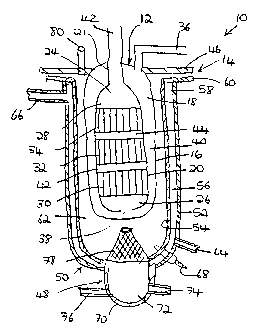
Reference is now made to Figure 1 of the drawings. Figure
1 shows a preferred embodiment of the invention, showing in
cross-section the configuration of an integrated reactor 10
comprised of essentially two components, namely, an autothermal
reformer assembly (ATR) 12, contained within an waste gas
oxidizer (WGO) assembly 14. It will be noted that the ATR
assembly 12 is generally located by insertion within the WGO 14
in a manner so as to benefit from the thermal output produced by
the WGO assembly 14, to be discussed in further detail below.
9
CA 02408077 2002-10-31
WO 01/77585 PCT/USO1/11085
The ATR assembly 12 comprises an external heat exchange wall
16 defining a chamber 18 in which is located the shell 20 of the
ATR assembly 12. The shell 20 has an upper end 24 and a lower end
26. In normal circumstances, and as will be described below,
process gases flow upwardly within the shell 20 from the lower
end 26 to the upper end 24. Within the shell 20, there is located
a series of catalysts through which process gases must pass as
they move through the chamber 28 defined by the shell 20 of the
ATR assembly 12.
In the embodiment shown in Figure l, three catalysts are
provided. The lowermost is a partial oxidation catalyst 30, and
two steam methane reform catalysts 32 and 34 are located serially
above the partial oxidation catalyst 30.
The chamber 18 defined by the heat exchange wall 16 includes
an inlet 36 through which process gases are introduced into the
chamber 18. These process gases may comprise a mixture of steam,
fuel and oxidant or air. At the base of the shell 20 there is
provided an opening 38 for the process gases, and through which
these process gases can flow into the chamber 28 defined by the
shell 20. Between the inlet 36 and opening 38, the heat exchange
wall 16 and the shell 20 together define a flow space 40, which
comprises the annular space between these two walls, for process
gas flow.
At the upper end of the shell 20, there is provided a
connection pipe 42, which may be in contact with a shift reactor
and carbon monoxide polishing unit, and through which the process
gases exit the ATR assembly 12 to be used and processed according
to the requirements of the system. As the gases exit catalyst 34,
they contact heat exchanger wall 21 and can transfer heat to
inlet gases from inlet 36 prior to entering flow space 40.
It will be noted that.the partial oxidation catalyst 30, as
well as both of the steam methane reform catalysts 32 and 34, are
located serially one above the other within the chamber 28, in
CA 02408077 2002-10-31
WO 01/77585 PCT/USO1/11085
such a manner that the process gases are forced to pass
therethrough.. The catalysts 30, 32 and 34 are arranged in
monolith form, with catalyst 30 and 32 being separated by space
42, and catalysts 32 and 34 being separated by space 44.
The ATR assembly 12 is attached to a lid 46 of the WGO
assembly 14 in conventional manner so as to be inserted and
suspended within the WGO 14 assembly as will be described.
The WGO assembly 14 comprises an waste gas combustor 48
supported at the lower end 50 of the WGO assembly 14. The WGO
assembly 14 comprises an outer steam generation shell 52, and an
inner steam generation heat exchange wall 54. The shell 52 and
heat exchange wall 54 define therebetween annular space 56 in
which water and steam and/or process gases are heated by thermal
energy produced by the waste gas combustor 48, to be described.
The WGO assembly l4 has an upper end 58, terminating in a
rim or flange 60. The annular space 56 is sealed at the upper end
58, and the rim or flange 60 engages the lid 46, so that the heat
exchange wall 54, and the lid 46, define a sealed chamber 62.
The annular space 56 is supplied with a water connection 64
near the lower end 50 of the WGO assembly 14 through which water,
or steam, supplied from a source (not shown) can be introduced
into the annular space 56. A steam exit connector 66 is provided
near the upper end 58 of the WGO assembly 14, thereby providing
a passage for steam produced by the heated water to pass through
the annular space 56 in a direction extending from the water
connection 64 to the steam exit connection 66. The process gases
can also flow in the reverse direction entering at connection 66
and exiting at connection 64.
A spark plug or glow plug 68 is provided, and extends
through the shell 52 and heat exchange wall 54 so as to pass from
the exterior of the WGO assembly 14 into the sealed chamber 62.
The function of spark plug 68 is to initiate the oxidation of the
anode off-gas or superheated fuel in the WGO assembly 14. While
11
CA 02408077 2002-10-31
WO 01/77585 PCT/USO1/11085
the spark plug 68 in Figure 1 is shown located in the shell 52,
it could also be located in the wall of, and be a part of the
waste combustor 48.
The waste gas combustor 48 comprises a wall 70 which defines
a combustor mix chamber 72. Waste gas from a fuel cell enters the
combustor mix chamber 72 through connection 74, while cathode-off
gas enters the combustor mix chamber 72 through the connection
76. The waste gas combustor 48 includes surface combustor 78
which is mounted on the wall 70. As will be seen in Figure 1, the
wall 70, and combustor mix chamber 72 defined thereby, are
essentially located outside of the chamber 62, while the surface
combustor 78 portion of the waste gas combustor 48 is located
within the chamber 62. Connections 74 and 76 can also be
integrated into a tube-in-tube configuration to enhance mixing
and control flash back.
As will be fully described below with respect to the
operation of the integrated reactor 10 of the invention, fuel
cell electrode off-gases are introduced into the chamber 62 of
the WGO assembly 14 through the surface combustor 78, and flow
through the chamber upwardly, eventually being discharged through
exit connection 80 which can be formed in the lid 46 of the WGO
assembly 14.
In the operation of the integrated reactor 10 shown in
Figure 1 of the drawings, process gases are coursed through the
autothermal reactor assembly 12, while, at the same time, gases
are combusted and produced within the waste gas combustor, and
the thermal energy produced thereby interfaces with the process
gases in the ATR assembly 12, providing thermal energy thereto,
enhancing its efficiency and output.
' In one aspect of the operation, process gases consisting of
steam, fuel and oxidant are introduced through the inlet 36 and
pass into the chamber 18 of the ATR assembly 12. These process
gases move downwardly through the-chamber, and eventually reach
12
CA 02408077 2002-10-31
WO 01/77585 PCT/USO1/11085
opening 38, thereafter being forced into the chamber 28. The
process gases move upwardly from the lower end of the chamber 28
to the upper end 24 thereof, at the same time passing through the
partial oxidation catalyst 30, space 42, the first steam methane
reforming catalyst 32, space 44 and then through the second steam
methane reform catalyst 34.
The process gases, upon reaching the upper end 24, of the
chamber 18 exit through the connection pipe 42, for further
processing. In one embodiment of the invention, as will be
described with reference to Figures 2 and 3 of the invention,
these treated process gases are conveyed to a shift reactor and
CO polishing unit.
Within the partial oxidation catalyst 30, the fuel and
oxidant portion of the processed gases react to form hydrogen and
carbon monoxide, with the concomitant production of heat.
However, some of the incoming fuel comprising the process gases
does not react, and flows through the partial oxidation catalyst
30, and thereafter into the two sequentially arranged steam
methane reformer catalysts 32 and 34. In these steam methane
reformer catalysts 32 and 34, the previously unreacted fuel
reacts with the steam to form hydrogen and carbon dioxide. These
reacted process gases are the ones entering the upper end of the
chamber 28, and which are transmitted through the connection pipe
42 to the shift reactor or, other apparatus as desired.
During the course of the passage of the process gases
through the ATR assembly 12, the reaction of these process gases
is facilitated and enhanced by thermal energy produced in the WGO
assembly 14, in which the ATR assembly 12 is located. The
production of this thermal energy, and the utilization thereof
within the integrated reactor, commences with the mixing in the
combustor mix chamber 72 of waste gas from a fuel cell, which
enters through connection 74, and cathode-off gas or air, which
enters the chamber 72 through connector 76. Within the mix
13
CA 02408077 2002-10-31
WO 01/77585 PCT/USO1/11085
chamber 72, these two components form combustion gases which then
flow upwardly and through the surface combustor 78. Upon exiting
the surface combustor 78 the mixed combustion gases pass into the
chamber 62, and are ignited by the spark plug 68. The combustion,
of course, produces heat, and the thermal energy thereof imparted
to the surface combustor 78 radiates to the steam generation heat
exchanger wall 54 as well as to the external heat exchanger wall
16 which forms a jacket about the ATR assembly 12. This heat is
conducted by and transferred through the heat exchange wall 16,
which facilitates pre-heating of the mixed process gases which
are flowing through flow space 40 of the ATR assembly 12, as
described above. Thus, between the process gas inlet 36 and the
opening 38, the movement of the process gases through the flow
space 40 results in the heating thereof, the. heat being derived
from the thermal energy produced by the combustion reaction in
the chamber 62. The preheating of the process gases facilitates
and enhances the reaction of the gases as they pass through the
catalyst monolith located in the chamber 28 defined by the shell
20, and also reduces the air needed for the partial oxidation
reaction of the feed, thereby reducing the SR (stoichiometric
ratio) and associated nitrogen dilution.
In addition, the combustion of the gases in the vicinity of
the surface combustor 78 also results in the production of heat
which is transferred to and radiates through the heat exchange
wall 16, thereby providing heat to the annular flow spaces 40 and
38. As has been described, the annular spaces 40 and 38 have
process gases flowing therethrough, the gases being introduced
through the connection 36, and exiting through the, exit connector
42. Further, the steam generated from the water in the annular
space 56 results from the thermal energy being transferred and
conducted through the heat exchange wall 54.
The combustion gases from the surface combustor 78 travel
through the chamber 62 upwardly toward the lid 46 of the WGC
14
CA 02408077 2002-10-31
WO 01/77585 PCT/USO1/11085
assembly 14, exiting the system through the exit connection 80.
As will be described further below, the gases exiting through
connection 80 may simply be exhausted, or may be used to provide
heat for downstream combustion, or the pre-heating of one or more
of the process fuels.
In Figure 1 of the drawings, the surface combustor 78 is
generally of frusto-conical shape, having a mesh surface through
which the combustion gases can pass . Figure 4 of the drawings
shows an alternative variation in the shape of this surface
combustor 78a, which has a more rounded, oval or elliptical
shape. It will be appreciated that many different variations and
modifications of this shape may be used, so that, in the
operation of the context of the specific apparatus, maximum
production and utilization of the thermal energy produced by the
combustion gases in the waste gas combustor 48 is possible. For
example, in Figure 5, the lower end of the shell 16 is in close
proximity to a concave-shaped surface 78b which forms the surface
combustor.
With reference to Figure 2 of the drawings, there is shown
schematically a flow diagram version of the integrated reactor
system 10 of the invention. As will be seen in Figure 2, the
integrated reactor system 10 comprises an ATR reactor assembly
12 and an WGO assembly 14. Also shown is a shift reactor and
carbon monoxide polishing unit 90 which is located downstream of
the ATR assembly 12, for receiving the reacted process gases from
the ATR assembly 12 for further use and processing.
In Figure 2, air 92 flows through line 94, and waste gas 96
flows through line 98, to the WGO assembly 14. Upon combustion
of the air and gases in the WGO assembly 14, the combustion gases
and thermal energy produced by combustion move through line 100,
and are eventually exhausted through exit 102. Alternatively, the
exhaust gases and thermal energy may be further utilized to
facilitate downstream combustion or provide additional thermal
CA 02408077 2002-10-31
WO 01/77585 PCT/USO1/11085
energy exchange in other portions of the system.
Within line 100, there is a heat exchanger 104 in which, as
will be discussed below, the thermal energy within the combusted
gases is conducted, radiated or otherwise transferred to other
portions of the system for pre-heating and heating to facilitate
hydrogen production within the integrated reactor. The heat
exchanger cavity 104 is, in Figure 2, schematically located
within a heat transfer area 106, with the heat exchanger cavity
104 being in close proximity to other surfaces to impart the
thermal energy.
In a parallel, but separate and independent system, air,
fuel and water are transmitted through the ATR assembly 12. Air
108 is transmitted through line 114 to line 120. Fuel 110 is
transmitted through line 116, also to line 120. Finally, water
or steam 112 is transmitted through line 118 to line 120. Line
120 constitutes that part of the system at which the air 108,
fuel 110 and water 112 are mixed, forming the mixed process gases
which will be subsequently transmitted to the ATR assembly 12,
and through the various catalysts therein. (In Figure 2, the ATR
assembly 12 is shown diagrammatically, and the catalysts therein
are not specifically identified in the drawing).
In the embodiment shown in Figure 2, the air 108 and fuel
110 are conveyed to line 120 without any pre-heating. However,
it will be noted that the water 112, traveling through line 118,
passes through the heat transfer area 106, and therein receives
thermal input from the heat exchanger cavity 104. The line 118
incorporates heat exchanger 121 which is positioned to receive
thermal energy from heat exchanger cavity 104, all in the heat
transfer area 106. Thus, the water 112 in line 118 is heated so
that the water, prior to mixing with the air and fuel in line
120, is either hot or converted to steam. Alternatively, in an
embodiment not shown, line 120 where process gases are mixed can
occur prior to heat exchange passage 121.
16
CA 02408077 2002-10-31
WO 01/77585 PCT/USO1/11085
Line 120, containing the mixed air, fuel and water process
gases, incorporates heat exchanger 123 as it passes through the
heat transfer area 106, also receiving thermal input from heat
energy in the heat exchanger cavity 104, produced by the WGO
assembly 14. The heated process gases are then conveyed to the
ATR assembly 12, and are treated as described above.
It will be noted that the pre-heating of the water 112 in
line 118 corresponds generally with the heating of the water
within the annular space 56 shown in Figure 1 of the drawings.
On the other hand, the heating of the process gases in line 120
shown in Figure 2 would corre$pond to the heating of these gases
as they flow generally through the flow space 40 shown in Figure
1 of the drawings, and receive thermal input produced by
combustion at the surface combustor 78, the heat of which is
transferred through the heat exchange wall 16.
The process gases, upon reaction within the auto-thermal
reactor assembly 12, exit the reactor through line 122. This line
corresponds to the exit connection 80 shown in Figure 1 of the
drawings. These reacted process gases are moved, in the
embodiment shown in Figure 2, to a shift reactor and carbon
monoxide polishing unit 90. The reacted gases or part thereof
exit the shift reactor 90 through line 124, and are directed by
a valve 126, according to the nature of the gases, either back
to the WGO assembly 14 as product gas, along line 128, or are
transmitted down line 130 to the fuel cell. Within the fuel cell,
hydrogen is depleted to form an anode-off gas stream 96 which
flows to WGO assembly 14 through line 98.
In Figure 2, the line 94 may be used to introduce air or
cathode-off gas, comprising depleted air from the fuel cell, and
these are transmitted to the WGO assembly 14. The contents of
lines 94 and line 98 enter the WGO assembly 14, and are ignited,
thereby providing the hot combustion gases which thereafter flow
through the line 100, and particularly through the heat exchanger
17
CA 02408077 2002-10-31
WO 01/77585 PCT/USO1/11085
cavity 104 which is the source of considerable thermal input for
~ the water in line 118, and the process gas mixture in line 120,
as already described.
Reference is now made to Figure 3 of the drawings which
shows a system using the integrated reactor 10 of the invention,
but constitutes a more comprehensive system of thermal transfer
so as to better utilize the heat energy produced by, and
available within, the system. The integrated reactor 10 also
comprises the autothermal reactor assembly 12, the waste gas
oxidizer assembly of 14 and a shift reactor and carbon monoxide
polishing unit 90. While the basic flow of combustion gases in
the WGO assembly 14, and process gasses in the ATR assembly 12
remain essentially the same as that described with respect to
Figure 2 of. the drawings, different and/or additional pathways
are provided to maximize the use of thermal energy produced.
Air or cathode-off gas 92 is introduced to the WGO assembly
14 through line 94, and waste gas 96 is also introduced to the
WGO assembly through line 98. The air or cathode-off gas, and the
waste gas, are mixed in the WGO assembly 14 and combusted to
produce substantial amounts of heat. The combustion gases and
thermal energy pass through line 100 and eventually exit through
the exhaust exit 102 at the end of the line. The line 100
incorporates heat exchanger cavity 104, located within a heat
transfer area 106. Further, a heat exchanger 132 is located
within line 100 prior to exit of the gases and their discharge
through exit 102. The heat exchanger 132 provides thermal energy
to incoming water, to be described further below. The heat
exchanger 132 is located within heat transfer cavity 134.
The ATR reactor assembly 12 is located within the WGO
assembly 14, in a manner the same as, or similar to, that
illustrated in Figure l, and works essentially independently of
the WGO assembly 14. In other words, the flow path of combustion
gases in the WGO assembly 14 is separate compared to the flow
18
CA 02408077 2002-10-31
WO 01/77585 PCT/USO1/11085
path of the process gases in the ATR assembly 12. However, the
two are integrated so that the ATR assembly 12 can maximize use
of the thermal energy produced by the WGO assembly 14. In Figure
3, fuel 110 is introduced to the ATR reactor assembly 12
initially through line 118. The line 118 ultimately transfers the
fuel into the line 120. Air 108 moves through line 114, and is
also ultimately discharged into the line 120, where it is mixed
with the fuel flowing from line 118. The air line 114
incorporates heat exchanger 136 which receives thermal input and
thus initial pre-heating, as described further below. A source
of water 138 is introduced through line 140, and this water 138
is also ultimately transferred into the line 120 for mixing of
the process gases. The line 140 incorporates a first heat
exchanger 142 and a second heat exchanger 144, so that the water
138 moving through line 140 are pre-heated by receiving thermal
input, to be described further below, as they pass through the
first and second heat exchangers 142 and 144. The fuel source 110
can also be mixed with the water prior to heat exchangers 142 and
144.
The fuel 110 in line 118, the water source 138 in line 140,
and heat in the first heat exchanger 142 and second heat
exchanger 144, as well as the air 108 from line 114 come together
and are mixed in line 120. The water source 138 is twice heated
by thermal energy produced by the combustion in the WGO assembly
14. It is first heated at the first heat exchanger 142 by thermal
input from the heat exchanger 132, and once again heated at its
second heat exchanger 144 by thermal energy available at the heat
exchanger cavity 104. Thus, the hydrocarbon water source 138 has
undergone significant pre-heating at the two heat exchange
transfer areas 106 and 134.
The mixed process gases introduced into line 120 also pass
through the heat transfer area 106, at which point a heat
exchanger 146 in line 120 receives thermal input from the heat
19
CA 02408077 2002-10-31
WO 01/77585 PCT/USO1/11085
exchanger cavity 104. After passing through the heat transfer
area 106, the process gases are moved to the ATR reactor assembly
12 where they undergo reaction and processing, as has been
described with respect to Figure 1. The reacted gases exit the
ATR reactor assembly 12 through line 122 and are moved to the
shift reactor and carbon, monoxide polishing unit 90. On route,
the line 122 incorporates heat exchanger 148 which is proximal
the heat exchanger 136 in the air line 114. Residual thermal
energy in the process gases exiting the ATR reactor assembly 12
may be transferred within the heat transfer cavity 150 to the
incoming air. Upon exiting the shift reactor and carbon monoxide
polishing unit 90, the various gases are directed either to the
WGO assembly 14 or a fuel cell 152 according to the setting of
valve 126.
From the description above, it will be appreciated that the
system described with respect to Figure 3 of the drawings
incorporates additional heat exchangers which, by more fully
utilizing thermal energy produced in both the WGO assembly 14 and
the ATR assembly 12, results in the more efficient use and
disposition of the process gases. In other embodiments, the mix
point 120 can be incorporated into air stream 114 prior to heat
exchanger area 150.
Various embodiments and modifications can be used so as to
facilitate and maximize heat transfer between the flue gas
produced by combustion in the WGO assembly, on the one hand, and
the process gases flowing through the ATR assembly 12. For
example, metal monoliths may be used as catalyst carriers, since
they have better thermal conductivity than ceramic monoliths
which may normally be used, thereby allowing the heat energy to
be dissipated more quickly and effectively to various portions
of the monolith and catalyst to heat the process gases passing
therethrough. As an alternative, ceramic or metal foams may be
employed as catalyst carriers, as foams allow gases to transfer
CA 02408077 2002-10-31
WO 01/77585 PCT/USO1/11085
heat from the wall of the ATR assembly 12. As yet another
alternative, a pelletized catalyst can be used which may simply
be a variation of conventional steam methane reform catalysts
(such as Ni - on alumina), or noble metal catalysts, such as Pt
Rh or Pt-Pd on suitable supports, may be utilized.
In yet a further embodiment, a surface combustor such as a
metal fiber burner or a ceramic radiant burner may be employed
in the waste gas oxidizer assembly, with inwardly radiating
annular surfaces to facilitate better radiation and improved heat
transfer abilities.
Figures 6, 7, 8, 9 and 10 show variations with respect to
the autothermal reformer assembly 12 which may be used, all of
which may facilitate, in one way or another, improved thermal
transfer for heating the process gases. For example, with
reference to Figure 6, it will be seen that heat pipes 160 or
other transfer elements are used to facilitate transfer of heat
from the flue gas produced by the combustion in the WGO assembly
14 to the heat collection region 161 of heat pipe 160 to the heat
release regions 163.of heat pipe 160 to the process gas moving
between the various catalytic stages in the catalyst monolith.
In Figure 6, the heat pipe 160 extends vertically and is axially
aligned with the ATR assembly 12 through the various catalytic
layers.
In Figure 7, heat pipes or layers 162 and 164 are provided
transverse to the axis of the process gas flow, and also extend
through the shell 20 as well as the heat exchange wall 16
defining the autothermal reformer assembly 12. In this way,
radiation and conductivity of heat through these heat pipes or
layers 162 and 164 provide more opportunities for introducing the
heat at various points and locations within the catalytic
monolith.
Figure 8 shows yet another embodiment of conductive devices
placed in the autothermal reformer assembly 12, and these
21
CA 02408077 2002-10-31
WO 01/77585 PCT/USO1/11085
comprise a series of wedge-shape conductors 166 which help
transfer and dissipate the heat from within the chamber 62 of the
WGO assembly 14 right into the heart of the catalytic layers
within the ATR assembly 12.
With reference to Figure 9 of the drawings, there is shown
yet another embodiment showing a different arrangement of the
autothermal reactor assembly 12, the catalysts therein, and the
flow path of the process gases through the catalyst. In Figure
9, the ATR assembly 168 comprises an external jacket 170 and a
shell 172 contained therein. The jacket 170 and shell 172 define
an annular space 17 for the flow of process gases down to opening
182. This space 174 is continuous although not illustrated in the
specific cross-section shown in Figure 9. Three catalysts are
serially arranged, catalysts 176, 178 and 180 each being spaced
from one another. The shell 172 has an opening 182 through which
process gases enter a chamber 184 in much the same way as has
been described with respect to Figure 1 of the drawings.
Figure 9 illustrates the situation where the catalyst
monoliths are positioned in such a way such that a spiral process
gas path is created to maximize heat transfer from the WGO
assembly 14 flue gas to these process gases.
The process gases enter the space 174 through top end 186,
and travel down the space 174 in a spiral or helical fashion. At
the base, they enter the opening 182, and pass through catalyst
176. Upon exiting the catalyst 176, the gases are moved spirally
through space 187 so as to enter the catalyst 178. Upon exiting
catalyst 178, the gases once again are transmitted spirally
through the space 189 of the ATR assembly 12 until reaching
catalyst 180. After passing through the catalyst 180, the process
gases exit through connection pipe 188, and are processed in a
similar manner as described above with respect to Figure 1.
In Figure 9, the WGO assembly 14 is partially shown,
indicated by reference numeral 190. The WGO assembly 190 includes
22
CA 02408077 2002-10-31
WO 01/77585 PCT/USO1/11085
inwardly projecting fingers 192 which are configured so as to be
located to maximize heating of the process gases passing between
the catalyst section of the ATR assembly 168 at spaces 187 and
189. These fingers 192 are intended to heat the process gases as
they spiral upwards, through the catalyst and the chamber 184.
In Figure 10 of the drawings, a further embodiment is shown
which illustrates the positioning of the catalyst monolith in
such as way as to have a zigzag process gas path. The lowermost
catalyst 192 is located on metal support plate 194, while the
intermediate catalyst 196 is located above metal support plate
198. Finally, the upper catalyst .200 is located above metal plate
202, and below metal plate 204. As illustrated by the arrows in
Figure 10, the process gases move zigzag through the ATR assembly
12. Process gases entering at 186 flow between wall sections 201
and 203 through cavity 205. These gases are preheated by heat
from the WGO heat. The process gases exit cavity 205 through
space 207 entering cavity 182 which is functionally similar to
182 of Figure 9.
Reference is now made to Figure 11 of the drawings. Figure
11 is yet another embodiment of the present invention wherein an
ATR assembly 210 is configured so as to have three vertically
stacked doughnut shaped catalyst layers 212, 214, and 216. A
process gas inlet 218 is provided and extends through the center
holes 220 of the doughnut shaped layers 212, 214, and 216 and
terminates at or shortly after it passes through the center hole
220 of the doughnut shaped catalyst layer 216. There is a space
222 between catalyst layers 216 and 214, and a space 224 between
catalyst layers 214 and 212.-
In operation, the process gases flow through the inlet 218
in the center of the catalyst layers 212, 214 and 216 and exit
below the lowermost catalyst layer 216. The gases reverse flow
direction, and then pass substantially vertically upwards through
catalyst layers 212, 214 and 216 before exiting from ATR assembly
23
CA 02408077 2002-10-31
WO 01/77585 PCT/USO1/11085
210. This configuration facilitates improved heat transfer
between the process gas and the oxidized WGO waste off-gas. This
configuration also permits improved reaction characteristics and
increased yield in ATR assembly 210.
Reference is now made to Figures 12 and 13 of the drawings
showing yet a further embodiment of an integrated reactor 230 of
the invention. The integrated reactor 230 comprises an ATR
assembly 232 located in/adj acent to an WGO assembly 234 . The WGO
assembly 234 comprises a housing 236 defining a housing chamber
238 and a tubular insulated housing extension 240 connected to
the housing 236 and forming an extension chamber 242. The housing
chamber 238 and extension chamber 242 are in communication with
each other.
The ATR assembly comprises a catalyst chamber 244 including
four catalyst beds 246 stacked substantially vertically, and an
outlet heat exchange member 248 downstream of the catalyst beds
246.
The integrated reactor 230 further comprises an intermediate
wall structure 250 between the ATR assembly 232 and the WGO
assembly 234 for guiding and managing the flow of gases in the
integrated reactor 230. The wall structure 250 comprises an inner
wall 252 which has a closed lower end 254 and an open upper end
256 and an outer wall 258 which has a closed upper end 260 and
an open lower end 262. The housing extension 240 is received
within the wall structure 250 and is situated between the inner
wall 252 and outer wall 258. The inner wall 252 is located in the
extension chamber 242, and forms a container for the ATR assembly
232 which itself is located within the confines of the inner wall
252.
A jacket or envelope 266 surrounds the outer wall 258 and,
together with the outer wall 258, defines a flow path 268. A
process gas inlet connector 270 is formed in the jacket 266, and
process gas is introduced in to the flow path 268 through the
24
CA 02408077 2002-10-31
WO 01/77585 PCT/USO1/11085
connecter.
The WGO assembly 234 has an inlet connector 272 for
introducing waste and/or cathode-off gas in to the housing
chamber 238. The gases so introduced are combusted within the
housing chamber 238 and thereafter pass in to the extension
chamber 242, flowing in the space between inner wall 252 of the
wall structure 250 and the housing extension.240. At the closed
upper end 260 these gases reverse flow direction and flow down
in the space between the housing extension 240 and outer wall
258, eventually discharging through outlet port 274. During this
flow, thermal energy or heat is transferred to incoming process
gases flowing in a path to be described.
The incoming process gases enter the integrated reactor 230
through connector 270 and flow up flow path 268 to the open upper
end 256. During this flow, the process gases acquire thermal
energy from the hot gases produced by the WGO assembly and
flowing in the space between outer wall 258 and the housing
extension 240. At the open upper end 256, flow direction of the
process gases is reversed and the gases flow downwardly between
inner wall 252 and the outlet 248, and thereafter between the
inner wall 252 and the wall of the catalyst chamber 244. During
this flow, the incoming process gases acquire further thermal
input from the hot gases produced by the WGO assembly, which are
flowing through the space between the housing extension 240 and
the inner wall 252. Eventually, the incoming gases enter the
space 278 defined by the closed lower end 254 of the wall
structure 250, after which they pass through the catalyst beds
246, and undergo reaction as preciously described.
The embodiment of Figure 12 shows an extended and
substantial exposure of the incoming gases to the exothermic
products of reaction in the WGO assembly, providing an effective
and increased preheating of these incoming gases.
It will be apparent that other heat transfer configurations
CA 02408077 2002-10-31
WO 01/77585 PCT/USO1/11085
may be used for heating the water in the space 56 shown in Figure
1 of the drawings. For example, a limpet coil configuration 250,
as shown in Figure 14 of the drawings, may be used instead of the
jacket configuration to effect the heat transfer between the WGO
waste off-gas and the water. In another configuration, a helical
or internal heat transfer coil 252, as shown in Figure 15 of the
drawings, containing the water may be provided in the annular
space or chamber 62 formed between the heat exchange wall 54 of
the WGO assembly 14 and the heat exchange wall 16 of ATR assembly
12. These alternate configurations will be equally effective in
heating water to provide steam for the system.
It will be apparent from the foregoing description that the
integrated reactor of the present invention allows for operation
of the ATR assembly 12 with lower amounts of oxidant or air, thus
enabling it to achieve higher efficiencies. Furthermore, the
integrated reactor of the present invention also facilitates
transfer of a higher quality heat from the WGO assembly 14 into
the process gases of the ATR assembly 12.
Yet another advantage of the present invention is that the
integrated reactor can be constructed so as to be lighter in mass
and smaller in volume and hence lower in cost than comparable
reformers.
These and other advantages will become apparent to one of
ordinary skill in the art. It should be noted that the above
examples and embodiments of the present invention described above
are only meant to be representative in nature. Yet other
embodiments and variations of the present invention will be
apparent to one of ordinary skill in the art and are construed
as falling within the scope of the invention which should be
evaluated in light of the following claims.
26